1985 FORD GRANADA ECU
[x] Cancel search: ECUPage 32 of 255
10Unscrew the auxiliary shaft sprocket bolt
while holding the sprocket stationary with a
screwdriver inserted through one of the holes.
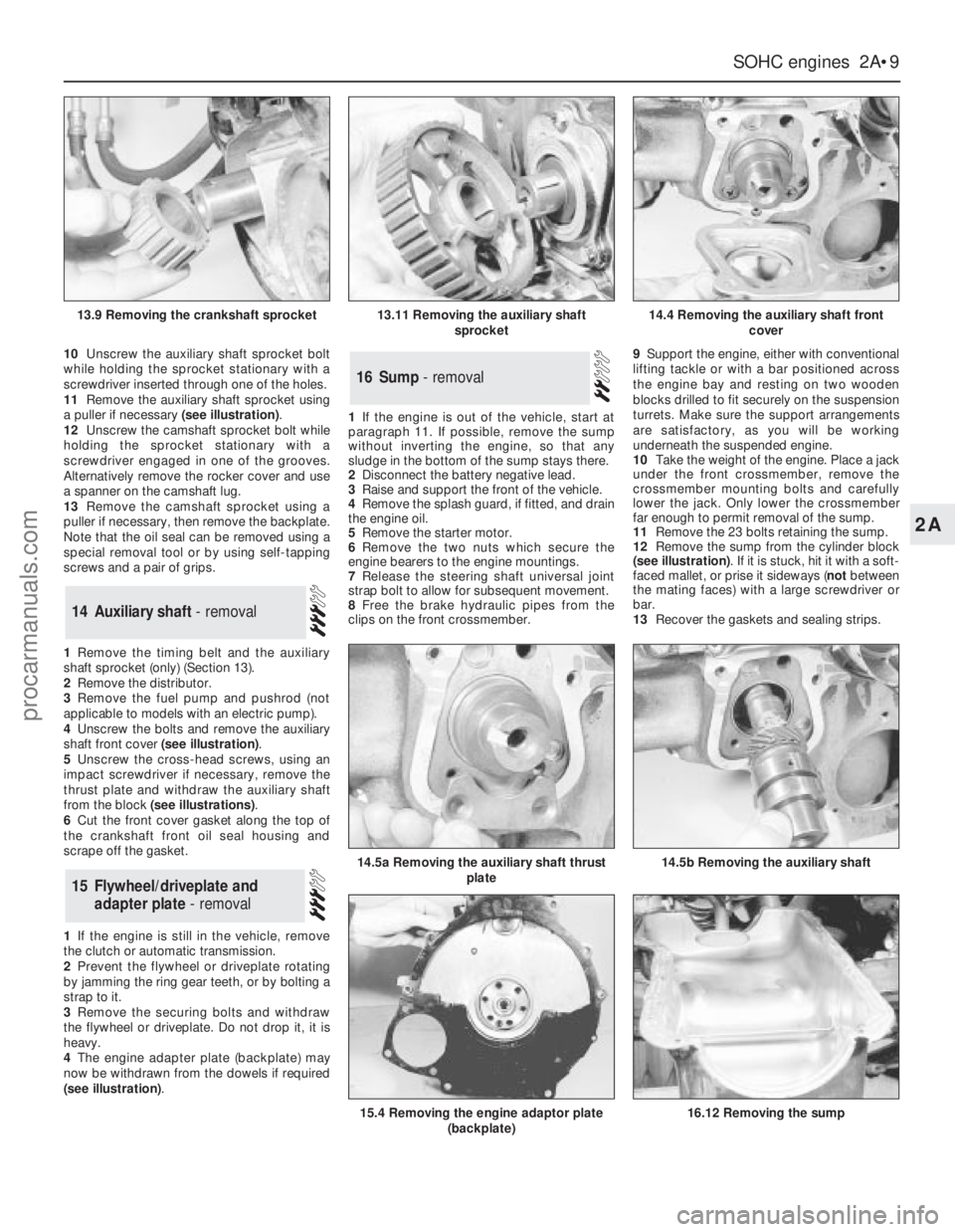
11Remove the auxiliary shaft sprocket using
a puller if necessary (see illustration).
12Unscrew the camshaft sprocket bolt while
holding the sprocket stationary with a
screwdriver engaged in one of the grooves.
Alternatively remove the rocker cover and use
a spanner on the camshaft lug.
13Remove the camshaft sprocket using a
puller if necessary, then remove the backplate.
Note that the oil seal can be removed using a
special removal tool or by using self-tapping
screws and a pair of grips.
1Remove the timing belt and the auxiliary
shaft sprocket (only) (Section 13).
2Remove the distributor.
3Remove the fuel pump and pushrod (not
applicable to models with an electric pump).
4Unscrew the bolts and remove the auxiliary
shaft front cover (see illustration).
5Unscrew the cross-head screws, using an
impact screwdriver if necessary, remove the
thrust plate and withdraw the auxiliary shaft
from the block (see illustrations).
6Cut the front cover gasket along the top of
the crankshaft front oil seal housing and
scrape off the gasket.
1If the engine is still in the vehicle, remove
the clutch or automatic transmission.
2Prevent the flywheel or driveplate rotating
by jamming the ring gear teeth, or by bolting a
strap to it.
3Remove the securing bolts and withdraw
the flywheel or driveplate. Do not drop it, it is
heavy.
4The engine adapter plate (backplate) may
now be withdrawn from the dowels if required
(see illustration).1If the engine is out of the vehicle, start at
paragraph 11. If possible, remove the sump
without inverting the engine, so that any
sludge in the bottom of the sump stays there.
2Disconnect the battery negative lead.
3Raise and support the front of the vehicle.
4Remove the splash guard, if fitted, and drain
the engine oil.
5Remove the starter motor.
6Remove the two nuts which secure the
engine bearers to the engine mountings.
7Release the steering shaft universal joint
strap bolt to allow for subsequent movement.
8Free the brake hydraulic pipes from the
clips on the front crossmember.9Support the engine, either with conventional
lifting tackle or with a bar positioned across
the engine bay and resting on two wooden
blocks drilled to fit securely on the suspension
turrets. Make sure the support arrangements
are satisfactory, as you will be working
underneath the suspended engine.
10Take the weight of the engine. Place a jack
under the front crossmember, remove the
crossmember mounting bolts and carefully
lower the jack. Only lower the crossmember
far enough to permit removal of the sump.
11Remove the 23 bolts retaining the sump.
12Remove the sump from the cylinder block
(see illustration). If it is stuck, hit it with a soft-
faced mallet, or prise it sideways (notbetween
the mating faces) with a large screwdriver or
bar.
13Recover the gaskets and sealing strips.
16Sump - removal
15Flywheel/driveplate and
adapter plate - removal
14Auxiliary shaft - removal
SOHCengines 2A•9
2A
13.9 Removing the crankshaft sprocket13.11 Removing the auxiliary shaft
sprocket14.4 Removing the auxiliary shaft front
cover
14.5b Removing the auxiliary shaft14.5a Removing the auxiliary shaft thrust
plate
15.4 Removing the engine adaptor plate
(backplate)16.12 Removing the sump
procarmanuals.com
Page 33 of 255
1Remove the timing belt and the crankshaft
sprocket (only).
2If an oil seal removal tool is available. the oil
seal can be removed at this stage. It may also
be possible to remove the oil seal by drilling
the outer face and using self-tapping screws
and a pair of grips.
3If the oil seal cannot be removed as
described in paragraph 2, remove the sump.
Also remove the auxiliary shaft sprocket.
Unbolt the oil seal housing and auxiliary shaft
front cover and remove the gasket. The oil seal
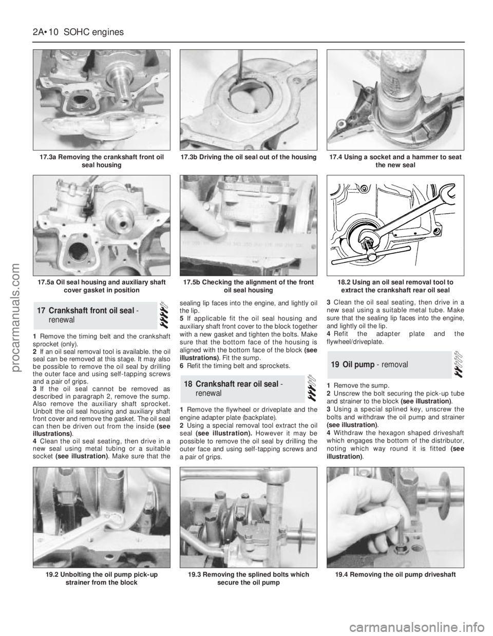
can then be driven out from the inside (see
illustrations).
4Clean the oil seal seating, then drive in a
new seal using metal tubing or a suitable
socket (see illustration). Make sure that thesealing lip faces into the engine, and lightly oil
the lip.
5If applicable fit the oil seal housing and
auxiliary shaft front cover to the block together
with a new gasket and tighten the bolts. Make
sure that the bottom face of the housing is
aligned with the bottom face of the block (see
illustrations). Fit the sump.
6Refit the timing belt and sprockets.
1Remove the flywheel or driveplate and the
engine adapter plate (backplate).
2Using a special removal tool extract the oil
seal (see illustration).However it may be
possible to remove the oil seal by drilling the
outer face and using self-tapping screws and
a pair of grips.3Clean the oil seal seating, then drive in a
new seal using a suitable metal tube. Make
sure that the sealing lip faces into the engine,
and lightly oil the lip.
4Refit the adapter plate and the
flywheel/driveplate.
1Remove the sump.
2Unscrew the bolt securing the pick-up tube
and strainer to the block (see illustration).
3Using a special splined key, unscrew the
bolts and withdraw the oil pump and strainer
(see illustration).
4Withdraw the hexagon shaped driveshaft
which engages the bottom of the distributor,
noting which way round it is fitted (see
illustration).
19Oil pump - removal
18Crankshaft rear oil seal -
renewal
17Crankshaft front oil seal -
renewal
2A•10SOHCengines
17.3a Removing the crankshaft front oil
seal housing
19.2 Unbolting the oil pump pick-up
strainer from the block19.3 Removing the splined bolts which
secure the oil pump19.4 Removing the oil pump driveshaft
18.2 Using an oil seal removal tool to
extract the crankshaft rear oil seal
17.3b Driving the oil seal out of the housing
17.5a Oil seal housing and auxiliary shaft
cover gasket in position17.5b Checking the alignment of the front
oil seal housing
17.4 Using a socket and a hammer to seat
the new seal
procarmanuals.com
Page 34 of 255
See Chapter 1, Section 8.
1Remove the sump and cylinder head.
2Check the big-end caps for identification
marks and if necessary use a centre-punch to
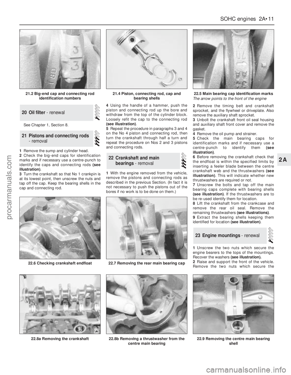
identify the caps and connecting rods (see
illustration).
3Turn the crankshaft so that No 1 crankpin is
at its lowest point, then unscrew the nuts and
tap off the cap. Keep the bearing shells in the
cap and connecting rod.4Using the handle of a hammer, push the
piston and connecting rod up the bore and
withdraw from the top of the cylinder block.
Loosely refit the cap to the connecting rod
(see illustration).
5Repeat the procedure in paragraphs 3 and 4
on the No 4 piston and connecting rod, then
turn the crankshaft through half a turn and
repeat the procedure on Nos 2 and 3 pistons
and connecting rods.
1With the engine removed from the vehicle,
remove the pistons and connecting rods as
described in the previous Section. (In fact it is
not necessary to push the pistons out of the
bores if no work is to be done on them.)2Remove the timing belt and crankshaft
sprocket, and the flywheel or driveplate. Also
remove the auxiliary shaft sprocket.
3Unbolt the crankshaft front oil seal housing
and auxiliary shaft front cover and remove the
gasket.
4Remove the oil pump and strainer.
5Check the main bearing caps for
identification marks and if necessary use a
centre-punch to identify them (see
illustration).
6Before removing the crankshaft check that
the endfloat is within the specified limits by
inserting a feeler blade between the centre
crankshaft web and the thrustwashers (see
illustration). This will indicate whether new
thrustwashers are required or not.
7Unscrew the bolts and tap off the main
bearing caps complete with bearing shells
(see illustration). If the thrustwashers are to
be re-used identify them for location.
8Lift the crankshaft from the crankcase and
remove the rear oil seal. Remove the
remaining thrustwashers (see illustrations).
9Extract the bearing shells keeping them
identified for location (see illustration).
1Unscrew the two nuts which secure the
engine bearers to the tops of the mountings.
Recover the washers(see illustration).
2Raise and support the front of the vehicle.
Remove the two nuts which secure the
23Engine mountings - renewal
22Crankshaft and main
bearings - removal
21Pistons and connecting rods
- removal
20Oil filter - renewal
SOHCengines 2A•11
2A
21.2 Big-end cap and connecting rod
identification numbers21.4 Piston, connecting rod, cap and
bearing shells22.5 Main bearing cap identification marks
The arrow points to the front of the engine
22.8a Removing the crankshaft
22.6 Checking crankshaft endfloat
22.8b Removing a thrustwasher from the
centre main bearing
22.7 Removing the rear main bearing cap
22.9 Removing the centre main bearing
shell
procarmanuals.com
Page 37 of 255
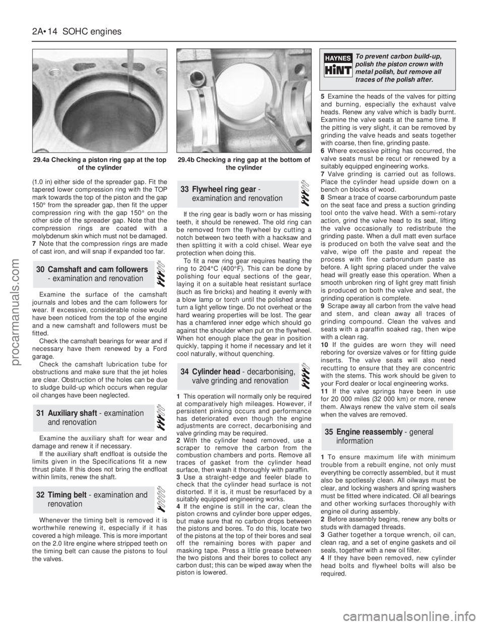
(1.0 in) either side of the spreader gap. Fit the
tapered lower compression ring with the TOP
mark towards the top of the piston and the gap
150°from the spreader gap, then fit the upper
compression ring with the gap 150°on the
other side of the spreader gap. Note that the
compression rings are coated with a
molybdenum skin which must not be damaged.
7Note that the compression rings are made
of cast iron, and will snap if expanded too far.
Examine the surface of the camshaft
journals and lobes and the cam followers for
wear. If excessive, considerable noise would
have been noticed from the top of the engine
and a new camshaft and followers must be
fitted.
Check the camshaft bearings for wear and if
necessary have them renewed by a Ford
garage.
Check the camshaft lubrication tube for
obstructions and make sure that the jet holes
are clear. Obstruction of the holes can be due
to sludge build-up which occurs when regular
oil changes have been neglected.
Examine the auxiliary shaft for wear and
damage and renew it if necessary.
If the auxiliary shaft endfloat is outside the
limits given in the Specifications fit a new
thrust plate. If this does not bring the endfloat
within limits, renew the shaft.
Whenever the timing belt is removed it is
worthwhile renewing it, especially if it has
covered a high mileage. This is more important
on the 2.0 litre engine where stripped teeth on
the timing belt can cause the pistons to foul
the valves.If the ring gear is badly worn or has missing
teeth, it should be renewed. The old ring can
be removed from the flywheel by cutting a
notch between two teeth with a hacksaw and
then splitting it with a cold chisel. Wear eye
protection when doing this.
To fit a new ring gear requires heating the
ring to 204°C (400°F). This can be done by
polishing four equal sections of the gear,
laying it on a suitable heat resistant surface
(such as fire bricks) and heating it evenly with
a blow lamp or torch until the polished areas
turn a light yellow tinge. Do not overheat or the
hard wearing properties will be lost. The gear
has a chamfered inner edge which should go
against the shoulder when put on the flywheel.
When hot enough place the gear in position
quickly, tapping it home if necessary and let it
cool naturally, without quenching.
1This operation will normally only be required
at comparatively high mileages. However, if
persistent pinking occurs and performance
has deteriorated even though the engine
adjustments are correct, decarbonising and
valve grinding may be required.
2With the cylinder head removed, use a
scraper to remove the carbon from the
combustion chambers and ports. Remove all
traces of gasket from the cylinder head
surface, then wash it thoroughly with paraffin.
3Use a straight-edge and feeler blade to
check that the cylinder head surface is not
distorted. If it is, it must be resurfaced by a
suitably equipped engineering works.
4If the engine is still in the car, clean the
piston crowns and cylinder bore upper edges,
but make sure that no carbon drops between
the pistons and bores. To do this, locate two
of the pistons at the top of their bores and seal
off the remaining bores with paper and
masking tape. Press a little grease between
the two pistons and their bores to collect any
carbon dust; this can be wiped away when the
piston is lowered.5Examine the heads of the valves for pitting
and burning, especially the exhaust valve
heads. Renew any valve which is badly burnt.
Examine the valve seats at the same time. If
the pitting is very slight, it can be removed by
grinding the valve heads and seats together
with coarse, then fine, grinding paste.
6Where excessive pitting has occurred, the
valve seats must be recut or renewed by a
suitably equipped engineering works.
7Valve grinding is carried out as follows.
Place the cylinder head upside down on a
bench on blocks of wood.
8Smear a trace of coarse carborundum paste
on the seat face and press a suction grinding
tool onto the valve head. With a semi-rotary
action, grind the valve head to its seat, lifting
the valve occasionally to redistribute the
grinding paste. When a dull matt even surface
is produced on both the valve seat and the
valve, wipe off the paste and repeat the
process with fine carborundum paste as
before. A light spring placed under the valve
head will greatly ease this operation. When a
smooth unbroken ring of light grey matt finish
is produced on both the valve and seat, the
grinding operation is complete.
9Scrape away all carbon from the valve head
and stem, and clean away all traces of
grinding compound. Clean the valves and
seats with a paraffin soaked rag, then wipe
with a clean rag.
10If the guides are worn they will need
reboring for oversize valves or for fitting guide
inserts. The valve seats will also need
recutting to ensure that they are concentric
with the stems. This work should be given to
your Ford dealer or local engineering works.
11If the valve springs have been in use
for 20 000 miles (32 000 km) or more, renew
them. Always renew the valve stem oil seals
when the valves are removed.
1To ensure maximum life with minimum
trouble from a rebuilt engine, not only must
everything be correctly assembled, but it must
also be spotlessly clean. All oilways must be
clear, and locking washers and spring washers
must be fitted where indicated. Oil all bearings
and other working surfaces thoroughly with
engine oil during assembly.
2Before assembly begins, renew any bolts or
studs with damaged threads.
3Gather together a torque wrench, oil can,
clean rag, and a set of engine gaskets and oil
seals, together with a new oil filter.
4If they have been removed, new cylinder
head bolts and flywheel bolts will also be
required.
35Engine reassembly - general
information
34Cylinder head - decarbonising,
valve grinding and renovation
33Flywheel ring gear -
examination and renovation
32Timing belt - examination and
renovation
31Auxiliary shaft - examination
and renovation
30Camshaft and cam followers
- examination and renovation
2A•14SOHCengines
29.4a Checking a piston ring gap at the top
of the cylinder29.4b Checking a ring gap at the bottom of
the cylinder
To prevent carbon build-up,
polish the piston crown with
metal polish, but remove all
traces of the polish after.
procarmanuals.com
Page 38 of 255
1Wipe the bearing shell locations in the
crankcase with a soft, non-fluffy rag.
2Wipe the crankshaft journals with a soft,
non-fluffy rag.
3Fit the five upper half main bearing shells to
their locations in the crankcase. If the old
shells are being re-used, make sure they are
refitted to their old locations.
4Identify each main bearing cap and place in
order. The number is cast onto the cap and on
intermediate caps an arrow is also marked
which should point towards front of engine.
5Wipe the cap bearing shell location with a
soft non-fluffy rag.
6Fit the bearing half shell onto each main
bearing cap.
7Apply a little grease to each side of the
centre main bearing so as to retain the
thrustwasher.
8Fit the upper halves of the thrustwashers
into their grooves either side of the main
bearing. The slots must face outwards.
9Lubricate the crankshaft journals and the
upper and lower main bearing shells with
engine oil and locate the rear oil seal (with lip
lubricated) on the rear of the crankshaft.
10Carefully lower the crankshaft into the
crankcase.
11Lubricate the crankshaft main bearing
journals again and then fit No 1 bearing cap. Fit
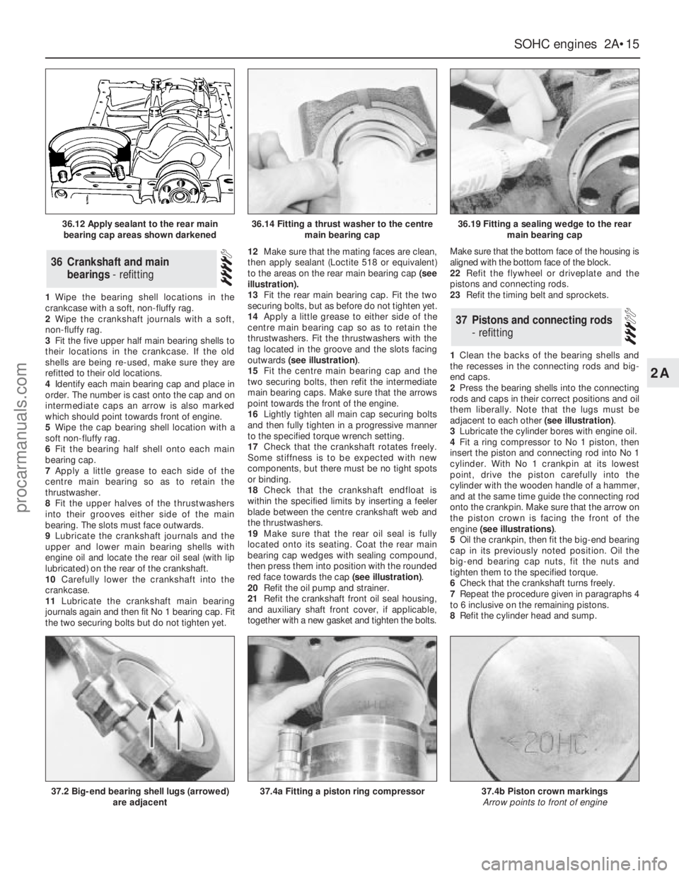
the two securing bolts but do not tighten yet.12Make sure that the mating faces are clean,
then apply sealant (Loctite 518 or equivalent)
to the areas on the rear main bearing cap (see
illustration).
13Fit the rear main bearing cap. Fit the two
securing bolts, but as before do not tighten yet.
14Apply a little grease to either side of the
centre main bearing cap so as to retain the
thrustwashers. Fit the thrustwashers with the
tag located in the groove and the slots facing
outwards (see illustration).
15Fit the centre main bearing cap and the
two securing bolts, then refit the intermediate
main bearing caps. Make sure that the arrows
point towards the front of the engine.
16Lightly tighten all main cap securing bolts
and then fully tighten in a progressive manner
to the specified torque wrench setting.
17Check that the crankshaft rotates freely.
Some stiffness is to be expected with new
components, but there must be no tight spots
or binding.
18Check that the crankshaft endfloat is
within the specified limits by inserting a feeler
blade between the centre crankshaft web and
the thrustwashers.
19Make sure that the rear oil seal is fully
located onto its seating. Coat the rear main
bearing cap wedges with sealing compound,
then press them into position with the rounded
red face towards the cap (see illustration).
20Refit the oil pump and strainer.
21Refit the crankshaft front oil seal housing,
and auxiliary shaft front cover, if applicable,
together with a new gasket and tighten the bolts.Make sure that the bottom face of the housing is
aligned with the bottom face of the block.
22Refit the flywheel or driveplate and the
pistons and connecting rods.
23Refit the timing belt and sprockets.
1Clean the backs of the bearing shells and
the recesses in the connecting rods and big-
end caps.
2Press the bearing shells into the connecting
rods and caps in their correct positions and oil
them liberally. Note that the lugs must be
adjacent to each other (see illustration).
3Lubricate the cylinder bores with engine oil.
4Fit a ring compressor to No 1 piston, then
insert the piston and connecting rod into No 1
cylinder. With No 1 crankpin at its lowest
point, drive the piston carefully into the
cylinder with the wooden handle of a hammer,
and at the same time guide the connecting rod
onto the crankpin. Make sure that the arrow on
the piston crown is facing the front of the
engine (see illustrations).
5Oil the crankpin, then fit the big-end bearing
cap in its previously noted position. Oil the
big-end bearing cap nuts, fit the nuts and
tighten them to the specified torque.
6Check that the crankshaft turns freely.
7Repeat the procedure given in paragraphs 4
to 6 inclusive on the remaining pistons.
8Refit the cylinder head and sump.
37Pistons and connecting rods
- refitting
36Crankshaft and main
bearings - refitting
SOHCengines 2A•15
2A
36.12 Apply sealant to the rear main
bearing cap areas shown darkened36.14 Fitting a thrust washer to the centre
main bearing cap36.19 Fitting a sealing wedge to the rear
main bearing cap
37.2 Big-end bearing shell lugs (arrowed)
are adjacent37.4a Fitting a piston ring compressor37.4b Piston crown markings
Arrow points to front of engine
procarmanuals.com
Page 39 of 255
1Insert the oil pump driveshaft into the block
in its previously noted position.
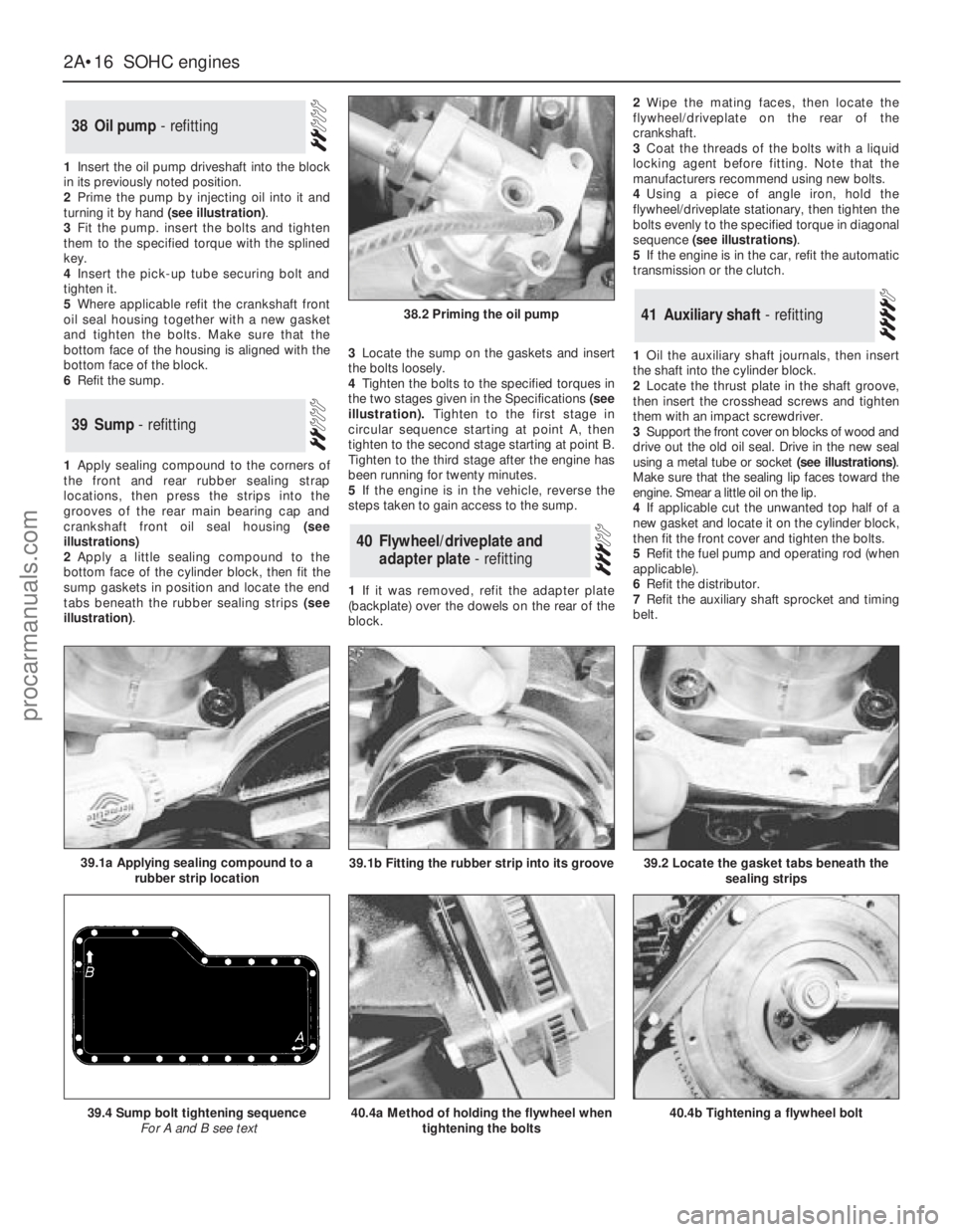
2Prime the pump by injecting oil into it and
turning it by hand (see illustration).
3Fit the pump. insert the bolts and tighten
them to the specified torque with the splined
key.
4Insert the pick-up tube securing bolt and
tighten it.
5Where applicable refit the crankshaft front
oil seal housing together with a new gasket
and tighten the bolts. Make sure that the
bottom face of the housing is aligned with the
bottom face of the block.
6Refit the sump.
1Apply sealing compound to the corners of
the front and rear rubber sealing strap
locations, then press the strips into the
grooves of the rear main bearing cap and
crankshaft front oil seal housing (see
illustrations)
2Apply a little sealing compound to the
bottom face of the cylinder block, then fit the
sump gaskets in position and locate the end
tabs beneath the rubber sealing strips (see
illustration).3Locate the sump on the gaskets and insert
the bolts loosely.
4Tighten the bolts to the specified torques in
the two stages given in the Specifications(see
illustration).Tighten to the first stage in
circular sequence starting at point A, then
tighten to the second stage starting at point B.
Tighten to the third stage after the engine has
been running for twenty minutes.
5If the engine is in the vehicle, reverse the
steps taken to gain access to the sump.
1If it was removed, refit the adapter plate
(backplate) over the dowels on the rear of the
block.2Wipe the mating faces, then locate the
flywheel/driveplate on the rear of the
crankshaft.
3Coat the threads of the bolts with a liquid
locking agent before fitting. Note that the
manufacturers recommend using new bolts.
4Using a piece of angle iron, hold the
flywheel/driveplate stationary, then tighten the
bolts evenly to the specified torque in diagonal
sequence (see illustrations).
5If the engine is in the car, refit the automatic
transmission or the clutch.
1Oil the auxiliary shaft journals, then insert
the shaft into the cylinder block.
2Locate the thrust plate in the shaft groove,
then insert the crosshead screws and tighten
them with an impact screwdriver.
3Support the front cover on blocks of wood and
drive out the old oil seal. Drive in the new seal
using a metal tube or socket (see illustrations).
Make sure that the sealing lip faces toward the
engine. Smear a little oil on the lip.
4If applicable cut the unwanted top half of a
new gasket and locate it on the cylinder block,
then fit the front cover and tighten the bolts.
5Refit the fuel pump and operating rod (when
applicable).
6Refit the distributor.
7Refit the auxiliary shaft sprocket and timing
belt.
41Auxiliary shaft - refitting
40Flywheel/driveplate and
adapter plate - refitting
39Sump - refitting
38Oil pump - refitting
2A•16SOHCengines
38.2 Priming the oil pump
40.4a Method of holding the flywheel when
tightening the bolts39.4 Sump bolt tightening sequence
For A and B see text40.4b Tightening a flywheel bolt
39.2 Locate the gasket tabs beneath the
sealing strips39.1a Applying sealing compound to a
rubber strip location39.1b Fitting the rubber strip into its groove
procarmanuals.com
Page 42 of 255
If the crankcase ventilation oil separator was
removed, apply a liquid locking agent to its
tube before pressing it into the cylinder block.
1Make sure that the clutch is centred.
2Apply a smear of grease or anti-seize
compound to the gearbox input shaft splines.
3With the aid of an assistant, offer the
gearbox to the engine. If the input shaft is
reluctant to enter the clutch, rock the gearbox
slightly or turn the crankshaft back and forth.
Support the gearbox until it is engaged with
the dowels on the engine - do not leave it
hanging on the input shaft.4Refit the engine-to-bellhousing bolts, the
bracing strap and the starter motor.
1Sling the engine/gearbox unit so that it
hangs at an angle of approximately 45°.
2Lower the unit into the engine bay, at the
same time moving it towards the rear of the
vehicle. Have an assistant watch as the unit is
lowered to check that no pipes, wires etc are
fouled or trapped.
3Raise the gearbox as the engine is lowered
until the unit takes up its correct position.
Secure the engine bearers to the mountings
and refit the gearbox crossmember.
4The remainder of refitting is a reversal of the
removal procedure. Refer to Section 6. Also
refer to Section 49, paragraph 9.
5Before starting the engine, refer to Section 51.
1On manual gearbox models, check that the
clutch is centred correctly. Apply a smear of
grease or anti-seize compound to the gearbox
input shaft.
2On automatic transmission models, check
that the torque converter is fully engaged with
the transmission oil pump.
3Sling the engine so that it is roughly horizontal.Lift it and position it over the engine bay.
4Lower the engine into place. Have an
assistant watch as the unit is lowered to check
that no pipes, wires etc are fouled or trapped.
5Guide the engine onto the transmission,
raising or lowering the transmission slightly if
necessary. Do not place any weight on the
transmission input shaft. With manual gearbox
models, rock the engine gently from side to
side to encourage the input shaft to enter the
clutch.
6When the engine and transmission are fully
engaged, refit the engine-to-bellhousing bolts.
Do not overlook the earth strap.
7Lower the engine so that the engine bearers
engage with the mountings. Fit the mounting
nuts and remove the lifting tackle.
8On automatic transmission models, bolt the
torque converter to the driveplate.
9The remainder of refitting is a reversal of the
removal procedure. Note the following
additional points:
a)Refill the engine with oil
b)Check the transmission oil level if
necessary
c)Adjust the tension of the accessory
drivebelts
d)Adjust the throttle cable
e)Adjust the downshift cable when
applicable
f)Refill the cooling system
10Before starting the engine, see Section 51
49Engine - refitting without
gearbox/transmission
48Engine - refitting with manual
gearbox
47Engine and gearbox -
reconnection
SOHCengines 2A•19
2A
45.16 Holding the crankshaft pulley with
two bolts and a lever while tightening the
central bolt
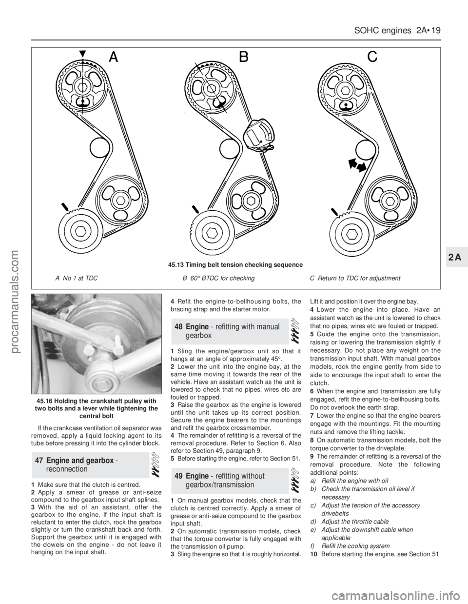
45.13 Timing belt tension checking sequence
A No 1 at TDCB 60°BTDC for checkingC Return to TDC for adjustment
procarmanuals.com
Page 47 of 255
manifold. Piston blow-by gases are drawn
through the oil separator and the vent valve to
the inlet manifold. The blow-by gases are then
drawn into the engine together with the fuel/air
mixture. Refer to Chapter 1 for maintenance of
the system.
The following operations can be carried out
without removing the engine from the vehicle.
a)Removal of the camshafts.
b)Removal and servicing of the cylinder
head.
c)Removal of the timing chain and
sprockets.
d)Removal of the oil pump.
e)Removal of the sump.
f)Removal of the pistons and connecting
rods.
g)Removal of the big-end bearings.
h)Removal of the engine mountings.
i)Removal of the clutch and flywheel.
j)Removal of the crankshaft front and rear
oil seals.
The following operations can only be carried
out after removing the engine from the vehicle.
a)Removal of the crankshaft main bearings.
b)Removal of the crankshaft.
Note: A hoist and lifting tackle will be required
to lift the engine out of the vehicle.
1Disconnect the battery negative lead.
2Remove the bonnet.
3On carburettor models, remove the air cleaner.
4On fuel-injection models, remove the air
inlet hose, plenum chamber and air cleaner lid
as an assembly.
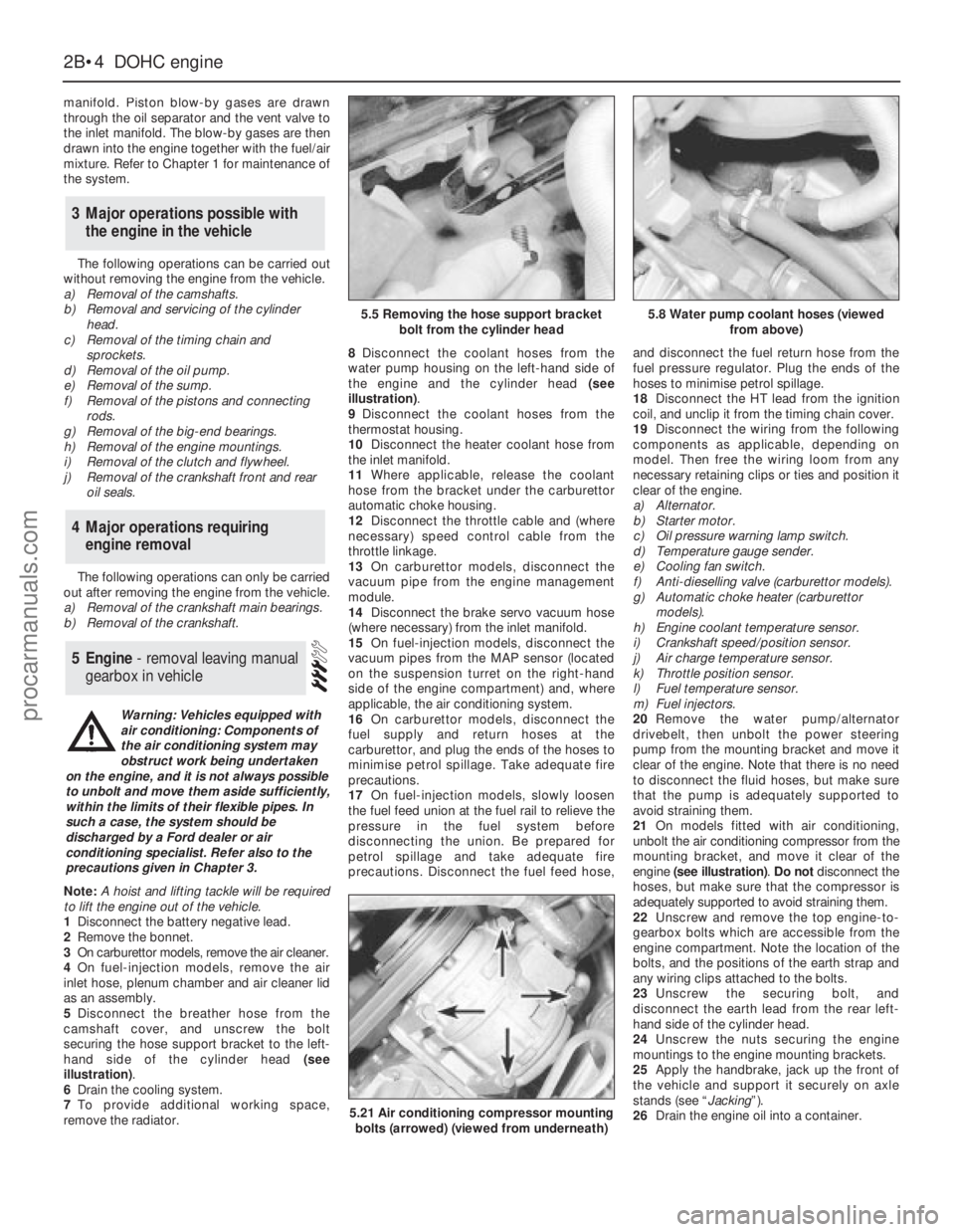
5Disconnect the breather hose from the
camshaft cover, and unscrew the bolt
securing the hose support bracket to the left-
hand side of the cylinder head (see
illustration).
6Drain the cooling system.
7To provide additional working space,
remove the radiator.8Disconnect the coolant hoses from the
water pump housing on the left-hand side of
the engine and the cylinder head (see
illustration).
9Disconnect the coolant hoses from the
thermostat housing.
10Disconnect the heater coolant hose from
the inlet manifold.
11Where applicable, release the coolant
hose from the bracket under the carburettor
automatic choke housing.
12Disconnect the throttle cable and (where
necessary) speed control cable from the
throttle linkage.
13On carburettor models, disconnect the
vacuum pipe from the engine management
module.
14Disconnect the brake servo vacuum hose
(where necessary) from the inlet manifold.
15On fuel-injection models, disconnect the
vacuum pipes from the MAP sensor (located
on the suspension turret on the right-hand
side of the engine compartment) and, where
applicable, the air conditioning system.
16On carburettor models, disconnect the
fuel supply and return hoses at the
carburettor, and plug the ends of the hoses to
minimise petrol spillage. Take adequate fire
precautions.
17On fuel-injection models, slowly loosen
the fuel feed union at the fuel rail to relieve the
pressure in the fuel system before
disconnecting the union. Be prepared for
petrol spillage and take adequate fire
precautions. Disconnect the fuel feed hose,and disconnect the fuel return hose from the
fuel pressure regulator. Plug the ends of the
hoses to minimise petrol spillage.
18Disconnect the HT lead from the ignition
coil, and unclip it from the timing chain cover.
19Disconnect the wiring from the following
components as applicable, depending on
model. Then free the wiring loom from any
necessary retaining clips or ties and position it
clear of the engine.
a)Alternator.
b)Starter motor.
c)Oil pressure warning lamp switch.
d)Temperature gauge sender.
e)Cooling fan switch.
f)Anti-dieselling valve (carburettor models).
g)Automatic choke heater (carburettor
models).
h)Engine coolant temperature sensor.
i)Crankshaft speed/position sensor.
j)Air charge temperature sensor.
k)Throttle position sensor.
l)Fuel temperature sensor.
m)Fuel injectors.
20Remove the water pump/alternator
drivebelt, then unbolt the power steering
pump from the mounting bracket and move it
clear of the engine. Note that there is no need
to disconnect the fluid hoses, but make sure
that the pump is adequately supported to
avoid straining them.
21On models fitted with air conditioning,
unbolt the air conditioning compressor from the
mounting bracket, and move it clear of the
engine (see illustration). Do notdisconnect the
hoses, but make sure that the compressor is
adequately supported to avoid straining them.
22Unscrew and remove the top engine-to-
gearbox bolts which are accessible from the
engine compartment. Note the location of the
bolts, and the positions of the earth strap and
any wiring clips attached to the bolts.
23Unscrew the securing bolt, and
disconnect the earth lead from the rear left-
hand side of the cylinder head.
24Unscrew the nuts securing the engine
mountings to the engine mounting brackets.
25Apply the handbrake, jack up the front of
the vehicle and support it securely on axle
stands (see “Jacking”).
26Drain the engine oil into a container.
5Engine - removal leaving manual
gearbox in vehicle
4Major operations requiring
engine removal
3Major operations possible with
the engine in the vehicle
2B•4DOHCengine
5.5 Removing the hose support bracket
bolt from the cylinder head5.8 Water pump coolant hoses (viewed
from above)
5.21 Air conditioning compressor mounting
bolts (arrowed) (viewed from underneath)
Warning: Vehicles equipped with
air conditioning: Components of
the air conditioning system may
obstruct work being undertaken
on the engine, and it is not always possible
to unbolt and move them aside sufficiently,
within the limits of their flexible pipes. In
such a case, the system should be
discharged by a Ford dealer or air
conditioning specialist. Refer also to the
precautions given in Chapter 3.
procarmanuals.com