1985 FORD GRANADA ECU
[x] Cancel search: ECUPage 15 of 255
14Refit the other disturbed components.
15Run the engine and check that there are
no oil leaks from the rocker cover.
2.8 litre engine
16If the engine is in the vehicle, carry out the
preliminary steps:
a)Disconnect the battery negative lead
b)Remove the throttle mechanism cover, air
cleaner cover, airflow meters and inlet
trunking
c)Remove the HT leads from the spark plugs
and unclip them from the rocker cover
d)Unbolt and remove the rocker covers
17Although not essential, it will be easier to
turn the engine if the spark plugs are removed.
18Valve clearances must be adjusted with
the engine cold (less than 40°C/104°F).
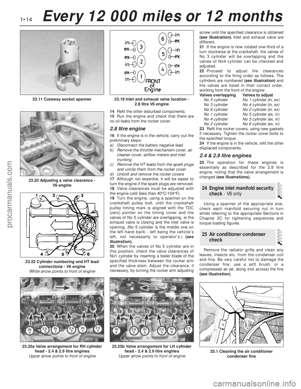
19Turn the engine, using a spanner on the
crankshaft pulley bolt, until the crankshaft
pulley timing mark is aligned with the TDC
(zero) pointer on the timing cover and the
valves of No 5 cylinder are overlapping, ie the
exhaust valve is closing and the inlet valve is
opening. (No 5 cylinder is the middle one on
the left-hand bank - left being the vehicle’s
left, not necessarily to operator’s.) (see
illustration).
20When the valves of No 5 cylinder are in
this position, check the valve clearances of
No1 cylinder by inserting a feeler blade of the
specified thickness between the rocker arm
and the valve stem. Adjust the clearance, if
necessary, by turning the rocker arm adjustingscrew until the specified clearance is obtained
(see illustration).Inlet and exhaust valve are
different.
21If the engine is now rotated one-third of a
turn clockwise at the crankshaft, the valves of
No 3 cylinder will be overlapping and the
valves of No4 cylinder can be checked and
adjusted.
22Proceed to adjust the clearances
according to the firing order as follows. The
cylinders are numbered (see illustration)and
the valves are listed in their correct order,
working from the front of the engine:
Valves overlappingValves to adjust
No 5 cylinderNo 1 cylinder (in, ex)
No 3 cylinderNo 4 cylinder (in, ex)
No 6 cylinderNo 2 cylinder (in, ex)
No 1 cylinderNo 5 cylinder (ex, in)
No 4 cylinderNo 3 cylinder (ex, in)
No 2 cylinderNo 6 cylinder (ex, in)
23Refit the rocker covers, using new gaskets
if necessary. Tighten the rocker cover bolts to
the specified torque.
24If the engine is in the vehicle, refit the other
displaced components.
2.4 & 2.9 litre engines
25The operation for these engines is
essentially as described for the 2.8 litre
engine, noting that the valve arrangement is
changed (see illustrations).
Using a spanner of the appropriate size,
check each manifold securing nut in turn
whilst referring to the appropriate Sections in
Chapter 2C for tightening sequences and
torque loading figures.
Remove the radiator grille and clean any
leaves, insects etc. from the condenser coil
and fins. Be very careful not to damage the
condenser fins: use a soft brush, or a
compressed air jet, along (not across) the fins
(see illustration).
25Air conditioner condenser
check
24Engine inlet manifold security
check - V6 only
1•14Every 12 000 miles or 12 months
23.19 Inlet and exhaust valve location -
2.8 litre V6 engine
23.20 Adjusting a valve clearance -
V6 engine
23.11 Cutaway socket spanner
23.25a Valve arrangement for RH cylinder
head - 2.4 & 2.9 litre engines
Upper arrow points to front of engine23.25b Valve arrangement for LH cylinder
head - 2.4 & 2.9 litre engines
Upper arrow points to front of engine
23.22 Cylinder numbering and HT lead
connections - V6 engine
White arrow points to front of engine
25.1 Cleaning the air conditioner
condenser fins
procarmanuals.com
Page 16 of 255
1Remove the radiator grille being careful not
to damage the condenser fins.
2Check the refrigerant charge as follows. The
engine should be cold and the ambient
temperature should be between 18°and 25°C
(64°and 77°F).
3Start the engine and allow it to idle. Observe
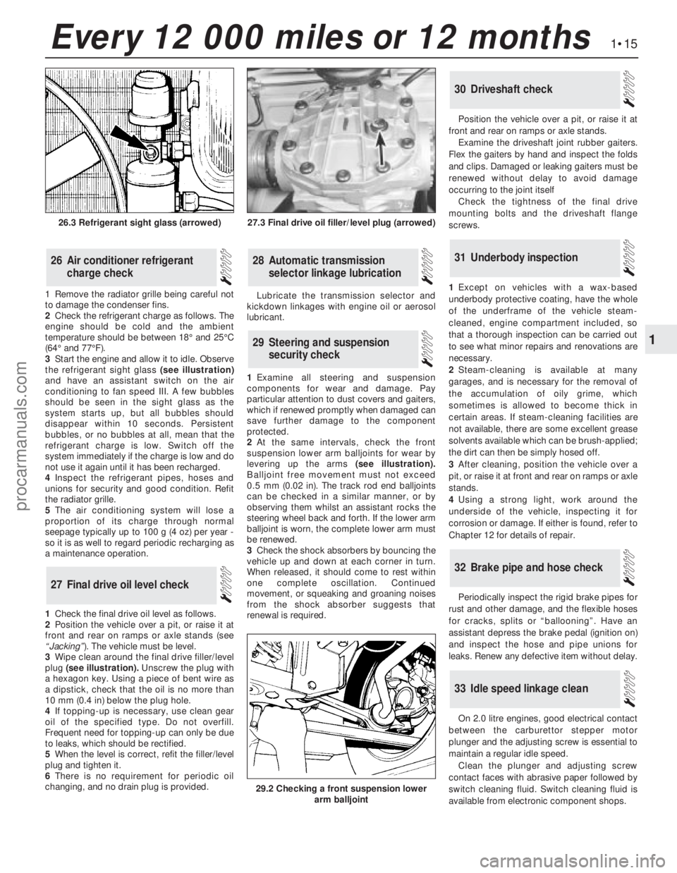
the refrigerant sight glass(see illustration)
and have an assistant switch on the air
conditioning to fan speed III. A few bubbles
should be seen in the sight glass as the
system starts up, but all bubbles should
disappear within 10 seconds. Persistent
bubbles, or no bubbles at all, mean that the
refrigerant charge is low. Switch off the
system immediately if the charge is low and do
not use it again until it has been recharged.
4Inspect the refrigerant pipes, hoses and
unions for security and good condition. Refit
the radiator grille.
5The air conditioning system will lose a
proportion of its charge through normal
seepage typically up to 100 g (4 oz) per year -
so it is as well to regard periodic recharging as
a maintenance operation.
1Check the final drive oil level as follows.
2Position the vehicle over a pit, or raise it at
front and rear on ramps or axle stands (see
“Jacking”). The vehicle must be level.
3Wipe clean around the final drive filler/level
plug (see illustration).Unscrew the plug with
a hexagon key. Using a piece of bent wire as
a dipstick, check that the oil is no more than
10 mm (0.4 in) below the plug hole.
4If topping-up is necessary, use clean gear
oil of the specified type. Do not overfill.
Frequent need for topping-up can only be due
to leaks, which should be rectified.
5When the level is correct, refit the filler/level
plug and tighten it.
6There is no requirement for periodic oil
changing, and no drain plug is provided. Lubricate the transmission selector and
kickdown linkages with engine oil or aerosol
lubricant.
1Examine all steering and suspension
components for wear and damage. Pay
particular attention to dust covers and gaiters,
which if renewed promptly when damaged can
save further damage to the component
protected.
2At the same intervals, check the front
suspension lower arm balljoints for wear by
levering up the arms(see illustration).
Balljoint free movement must not exceed
0.5 mm (0.02 in). The track rod end balljoints
can be checked in a similar manner, or by
observing them whilst an assistant rocks the
steering wheel back and forth. If the lower arm
balljoint is worn, the complete lower arm must
be renewed.
3Check the shock absorbers by bouncing the
vehicle up and down at each corner in turn.
When released, it should come to rest within
one complete oscillation. Continued
movement, or squeaking and groaning noises
from the shock absorber suggests that
renewal is required.Position the vehicle over a pit, or raise it at
front and rear on ramps or axle stands.
Examine the driveshaft joint rubber gaiters.
Flex the gaiters by hand and inspect the folds
and clips. Damaged or leaking gaiters must be
renewed without delay to avoid damage
occurring to the joint itself
Check the tightness of the final drive
mounting bolts and the driveshaft flange
screws.
1Except on vehicles with a wax-based
underbody protective coating, have the whole
of the underframe of the vehicle steam-
cleaned, engine compartment included, so
that a thorough inspection can be carried out
to see what minor repairs and renovations are
necessary.
2Steam-cleaning is available at many
garages, and is necessary for the removal of
the accumulation of oily grime, which
sometimes is allowed to become thick in
certain areas. If steam-cleaning facilities are
not available, there are some excellent grease
solvents available which can be brush-applied;
the dirt can then be simply hosed off.
3After cleaning, position the vehicle over a
pit, or raise it at front and rear on ramps or axle
stands.
4Using a strong light, work around the
underside of the vehicle, inspecting it for
corrosion or damage. If either is found, refer to
Chapter 12 for details of repair.
Periodically inspect the rigid brake pipes for
rust and other damage, and the flexible hoses
for cracks, splits or “ballooning”. Have an
assistant depress the brake pedal (ignition on)
and inspect the hose and pipe unions for
leaks. Renew any defective item without delay.
On 2.0 litre engines, good electrical contact
between the carburettor stepper motor
plunger and the adjusting screw is essential to
maintain a regular idle speed.
Clean the plunger and adjusting screw
contact faces with abrasive paper followed by
switch cleaning fluid. Switch cleaning fluid is
available from electronic component shops.
33Idle speed linkage clean
32Brake pipe and hose check
31Underbody inspection
30Driveshaft check
29Steering and suspension
security check
28Automatic transmission
selector linkage lubrication
27Final drive oil level check
26Air conditioner refrigerant
charge check
1•15
1
Every 12 000 miles or 12 months
27.3 Final drive oil filler/level plug (arrowed)
29.2 Checking a front suspension lower
arm balljoint
26.3 Refrigerant sight glass (arrowed)
procarmanuals.com
Page 17 of 255
Instruments and electrical
equipment
1Check the operation of all instruments and
electrical equipment.
2Make sure that all instruments read
correctly, and switch on all electrical
equipment in turn to check that it functions
properly.
Steering and suspension
3Check for any abnormalities in the steering,
suspension, handling or road “feel”.
4Drive the vehicle, and check that there are
no unusual vibrations or noises.
5Check that the steering feels positive, with
no excessive “sloppiness”, or roughness, and
check for any suspension noises when
cornering, or when driving over bumps.
Drivetrain
6Check the performance of the engine,
clutch, transmission and driveshafts.
7Listen for any unusual noises from the
engine, clutch and transmission.
8Make sure that the engine runs smoothly
when idling, and that there is no hesitation
when accelerating.
9Where applicable, check that the clutch
action is smooth and progressive, that the
drive is taken up smoothly, and that the pedal
travel is not excessive. Also listen for any
noises when the clutch pedal is depressed.
10Check that all gears can be engaged
smoothly, without noise, and that the gear
lever action is not abnormally vague or
“notchy”.
Check the operation and
performance of the braking system
11Make sure that the vehicle does not pull to
one side when braking, and that the wheels do
not lock prematurely when braking hard.
12Check that there is no vibration through
the steering when braking.
13Check that the handbrake operates
correctly, without excessive movement of the
lever, and that it holds the vehicle stationary
on a slope.
14Test the operation of the brake servo unit
as follows. With the engine off, depress the
footbrake four or five times to exhaust the
vacuum. Start the engine, holding the brake
pedal depressed. As the engine starts, there
should be a noticeable “give” in the brake
pedal as vacuum builds up. Allow the engine
to run for at least two minutes, and then
switch it off. If the brake pedal is depressed
now, it should be possible to detect a hiss
from the servo as the pedal is depressed. After
about four or five applications, no further
hissing should be heard, and the pedal should
feel considerably firmer.1The power steering fluid dipstick is
incorporated in the reservoir filler cap. The
reservoir is mounted on the pump. Observe
scrupulous cleanliness when checking the
level or topping-up.
2The system should be at operating
temperature and the engine switched off.
Wipe clean around the reservoir filler cap.
Unscrew the cap, withdraw the dipstick and
wipe it with a clean lint-free rag. Reinsert the
dipstick, screw the cap home, then unscrew it
again and read the level on the dipstick. It
should be up to the MAX or upper HOT mark
(depending on the dipstick markings) (see
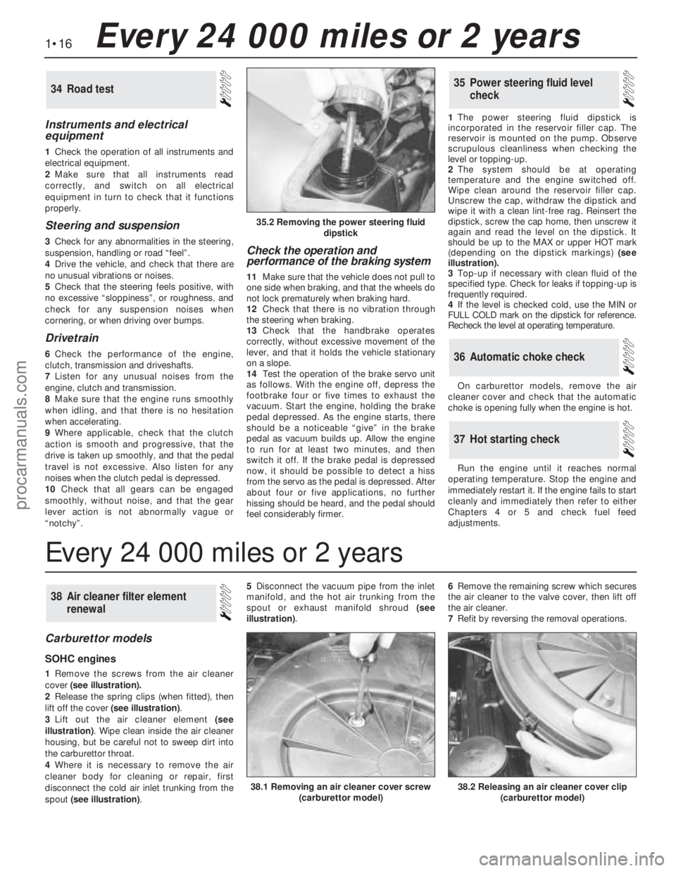
illustration).
3Top-up if necessary with clean fluid of the
specified type. Check for leaks if topping-up is
frequently required.
4If the level is checked cold, use the MIN or
FULL COLD mark on the dipstick for reference.
Recheck the level at operating temperature.
On carburettor models, remove the air
cleaner cover and check that the automatic
choke is opening fully when the engine is hot.
Run the engine until it reaches normal
operating temperature. Stop the engine and
immediately restart it. If the engine fails to start
cleanly and immediately then refer to either
Chapters 4 or 5 and check fuel feed
adjustments.
37Hot starting check
36Automatic choke check
35Power steering fluid level
check34Road test
Carburettor models
SOHC engines
1Remove the screws from the air cleaner
cover(see illustration).
2Release the spring clips (when fitted), then
lift off the cover (see illustration).
3Lift out the air cleaner element(see
illustration). Wipe clean inside the air cleaner
housing, but be careful not to sweep dirt into
the carburettor throat.
4Where it is necessary to remove the air
cleaner body for cleaning or repair, first
disconnect the cold air inlet trunking from the
spout (see illustration). 5Disconnect the vacuum pipe from the inlet
manifold, and the hot air trunking from the
spout or exhaust manifold shroud(see
illustration). 6Remove the remaining screw which secures
the air cleaner to the valve cover, then lift off
the air cleaner.
7Refit by reversing the removal operations.
38Air cleaner filter element
renewal
1•16Every 24 000 miles or 2 years
35.2 Removing the power steering fluid
dipstick
38.2 Releasing an air cleaner cover clip
(carburettor model)38.1 Removing an air cleaner cover screw
(carburettor model)
Every 24 000 miles or 2 years
procarmanuals.com
Page 18 of 255
DOHC engine
8Proceed as described above whilst noting
that the camshaft cover breather hose must
be disconnected before the air cleaner can be
removed.
Fuel-injection models
SOHC and V6 engines
9Release the four spring clips which secure
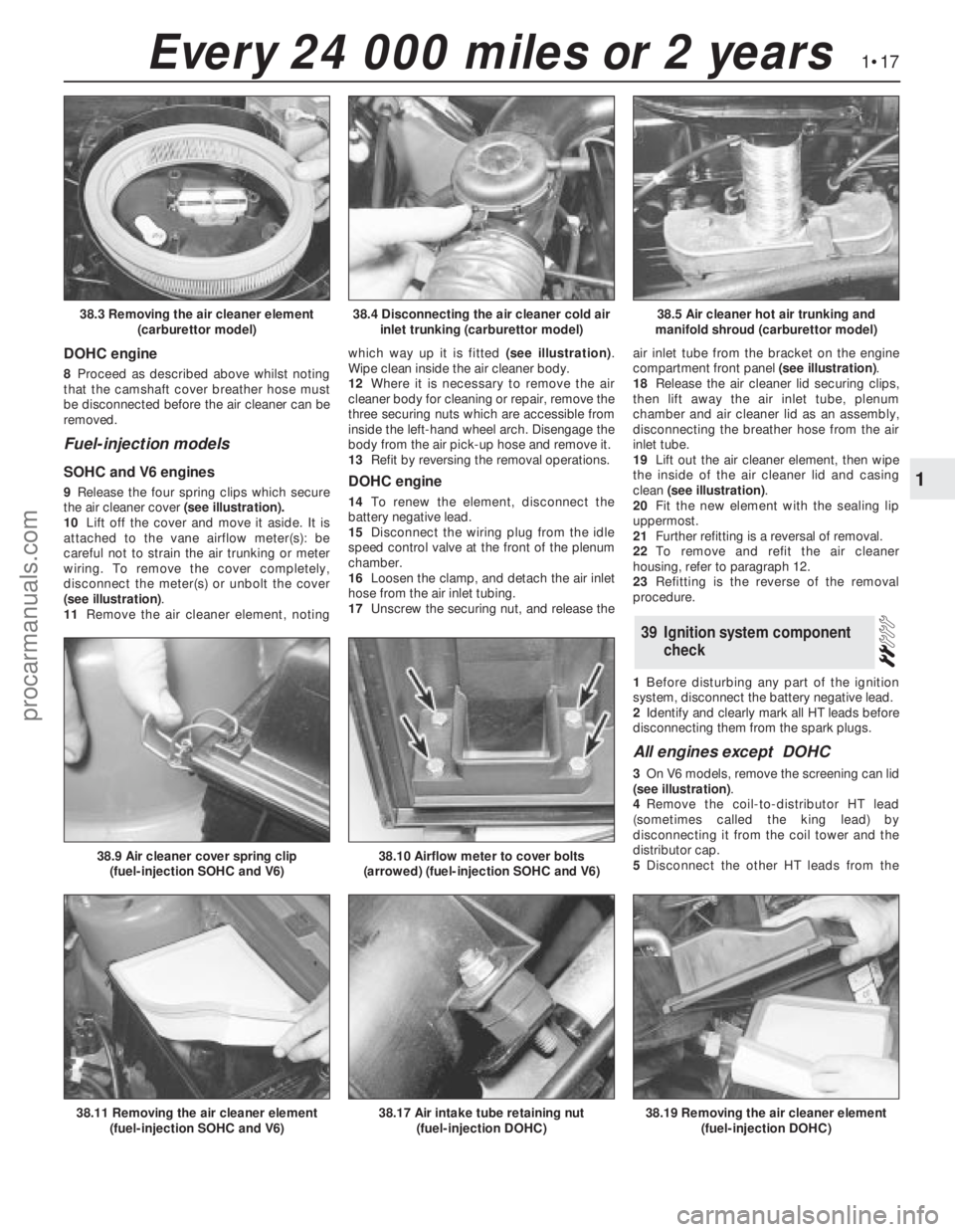
the air cleaner cover(see illustration).
10Lift off the cover and move it aside. It is
attached to the vane airflow meter(s): be
careful not to strain the air trunking or meter
wiring. To remove the cover completely,
disconnect the meter(s) or unbolt the cover
(see illustration).
11Remove the air cleaner element, notingwhich way up it is fitted (see illustration).
Wipe clean inside the air cleaner body.
12Where it is necessary to remove the air
cleaner body for cleaning or repair, remove the
three securing nuts which are accessible from
inside the left-hand wheel arch. Disengage the
body from the air pick-up hose and remove it.
13Refit by reversing the removal operations.DOHC engine
14To renewthe element, disconnect the
battery negative lead.
15Disconnect the wiring plug from the idle
speed control valve at the front of the plenum
chamber.
16Loosen the clamp, and detach the air inlet
hose from the air inlet tubing.
17Unscrew the securing nut, and release theair inlet tube from the bracket on the engine
compartment front panel (see illustration).
18Release the air cleaner lid securing clips,
then lift away the air inlet tube, plenum
chamber and air cleaner lid as an assembly,
disconnecting the breather hose from the air
inlet tube.
19Lift out the air cleaner element, then wipe
the inside of the air cleaner lid and casing
clean (see illustration).
20Fit the new element with the sealing lip
uppermost.
21Further refitting is a reversal of removal.
22To remove and refit the air cleaner
housing, refer to paragraph 12.
23Refitting is the reverse of the removal
procedure.
1Before disturbing any part of the ignition
system, disconnect the battery negative lead.
2Identify and clearly mark all HT leads before
disconnecting them from the spark plugs.
All engines except DOHC
3On V6 models, remove the screening can lid
(see illustration).
4Remove the coil-to-distributor HT lead
(sometimes called the king lead) by
disconnecting it from the coil tower and the
distributor cap.
5Disconnect the other HT leads from the
39Ignition system component
check
1•17
1
Every 24 000 miles or 2 years
38.4 Disconnecting the air cleaner cold air
inlet trunking (carburettor model)38.5 Air cleaner hot air trunking and
manifold shroud (carburettor model)38.3 Removing the air cleaner element
(carburettor model)
38.17 Air intake tube retaining nut
(fuel-injection DOHC)38.19 Removing the air cleaner element
(fuel-injection DOHC)38.11 Removing the air cleaner element
(fuel-injection SOHC and V6)
38.9 Air cleaner cover spring clip
(fuel-injection SOHC and V6)38.10 Airflow meter to cover bolts
(arrowed) (fuel-injection SOHC and V6)
procarmanuals.com
Page 19 of 255
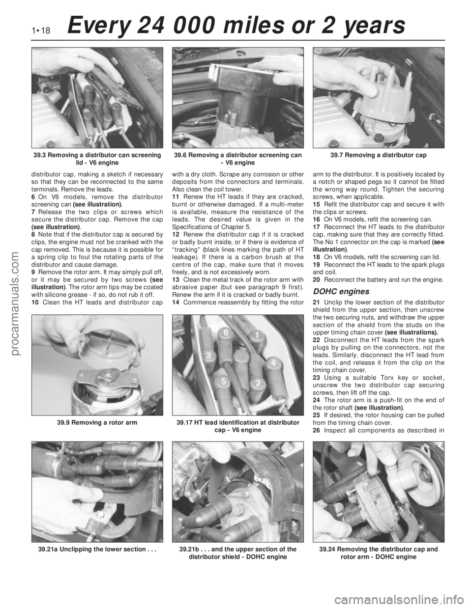
distributor cap, making a sketch if necessary
so that they can be reconnected to the same
terminals. Remove the leads.
6On V6 models, remove the distributor
screening can (see illustration).
7Release the two clips or screws which
secure the distributor cap. Remove the cap
(see illustration).
8Note that if the distributor cap is secured by
clips, the engine must not be cranked with the
cap removed. This is because it is possible for
a spring clip to foul the rotating parts of the
distributor and cause damage.
9Remove the rotor arm. It may simply pull off,
or it may be secured by two screws (see
illustration). The rotor arm tips may be coated
with silicone grease - if so, do not rub it off.
10Clean the HT leads and distributor capwith a dry cloth. Scrape any corrosion or other
deposits from the connectors and terminals.
Also clean the coil tower.
11Renew the HT leads if they are cracked,
burnt or otherwise damaged. If a multi-meter
is available, measure the resistance of the
leads. The desired value is given in the
Specifications of Chapter 5.
12Renew the distributor cap if it is cracked
or badly burnt inside, or if there is evidence of
“tracking” (black lines marking the path of HT
leakage). If there is a carbon brush at the
centre of the cap, make sure that it moves
freely, and is not excessively worn.
13Clean the metal track of the rotor arm with
abrasive paper (but see paragraph 9 first).
Renew the arm if it is cracked or badly burnt.
14Commence reassembly by fitting the rotorarm to the distributor. It is positively located by
a notch or shaped pegs so it cannot be fitted
the wrong way round. Tighten the securing
screws, when applicable.
15Refit the distributor cap and secure it with
the clips or screws.
16On V6 models, refit the screening can.
17Reconnect the HT leads to the distributor
cap, making sure that they are correctly fitted.
The No 1 connector on the cap is marked (see
illustration).
18On V6 models, refit the screening can lid.
19Reconnect the HT leads to the spark plugs
and coil.
20Reconnect the battery and run the engine.
DOHC engines
21Unclip the lower section of the distributor
shield from the upper section, then unscrew
the two securing nuts, and withdraw the upper
section of the shield from the studs on the
upper timing chain cover (see illustrations).
22Disconnect the HT leads from the spark
plugs by pulling on the connectors, not the
leads. Similarly, disconnect the HT lead from
the coil, and release it from the clip on the
timing chain cover.
23Using a suitable Torx key or socket,
unscrew the two distributor cap securing
screws, then lift off the cap.
24The rotor arm is a push-fit on the end of
the rotor shaft (see illustration).
25If desired, the rotor housing can be pulled
from the timing chain cover.
26Inspect all components as described in
1•18Every 24 000 miles or 2 years
39.6 Removing a distributor screening can
- V6 engine39.7 Removing a distributor cap39.3 Removing a distributor can screening
lid - V6 engine
39.21b . . . and the upper section of the
distributor shield - DOHC engine39.24 Removing the distributor cap and
rotor arm - DOHC engine39.21a Unclipping the lower section . . .
39.9 Removing a rotor arm39.17 HT lead identification at distributor
cap - V6 engine
procarmanuals.com
Page 28 of 255
The cylinder head is of crossflow design
with the inlet manifold mounted on the left-
hand side and the exhaust manifold mounted
on the right-hand side.
Lubrication is by means of a bi-rotor pump
which draws oil through a strainer located
inside the sump, and forces it through a full-
flow filter into the engine oil galleries where it
is distributed to the crankshaft, camshaft and
auxiliary shaft. The big-end bearings are
supplied with oil via internal drillings in the
crankshaft.The undersides of the pistons are
supplied with oil from drillings in the big-ends.
The distributor shaft is intermittently supplied
with oil from the drilled auxiliary shaft. The
camshaft and cam followers are supplied with
oil via a drilled spray tube from the centre
camshaft bearing.
A semi-closed crankcase ventilation system
is employed whereby piston blow-by gases
are drawn into the inlet manifold via an oil
separator and on carburettor models a control
valve.
The following operations can be carried out
without removing the engine, although the
work may be easier and quicker with the
engine removed:
a)Removal and refitting of the cylinder head
b)Removal and refitting of the camshaft
(after removing the cylinder head)
c)Removal and refitting of the timing belt
and sprockets
d)Removal and refitting of the sump and oil
pump
e)Removal and refitting of the pistons,
connecting rods and big-end bearings
f)Renewal of the engine mountings
g)Renewal of the crankshaft oil seals
h)Removal and refitting of the auxiliary shaft
j)Removal and refitting of the flywheel
The engine must be removed from the
vehicle for the following operations:
a)Renewal of the crankshaft main bearings
b)Removal and refitting of the crankshaft
The engine may be lifted out either on its
own or together with the gearbox. Unless work
is also necessary on the gearbox it is
recommended that the engine is removed on
its own. Where automatic transmission is
fitted, the engine should be removed on its
own owing to the additional weight. If the
engine and gearbox are removed together,
they will have to be tilted at a very steep angle;
make sure that the range of the lifting tackle is
adequate.1Disconnect the battery negative lead.
2Remove the bonnet.
3On carburettor models, remove the air
cleaner. On fuel-injection models, remove the
air cleaner cover, vane airflow meter and air
inlet trunking.
4If a splash guard is fitted, remove it.
5Release the securing clips and bolts and
remove the upper half of the fan shroud. On
carburettor models remove the lower half of
the shroud too.
6Drain the cooling system.
7Disconnect the radiator top and bottom
hoses from the thermostat housing and water
pump. Disconnect the top hose spur from the
expansion tank and unclip it.
8Disconnect the heater hoses from the water
pump and from the inlet manifold or automatic
choke housing. Unclip the hoses.
9On models with power steering, remove the
steering pump.
10Disconnect the vacuum pipe(s) from the
inlet manifold, labelling them if there is any
possibility of confusion.
11Disconnect the following wiring, as
applicable:
a)Alternator
b)Temperature gauge sender
c)Engine management temperature sensor
d)Distributor
e)Oil pressure switch
f)Automatic choke and thermo-switch
g)Carburettor stepper motor
h)Fuel-injection system sub-harness
j)Inlet manifold heater
12Disconnect the HT lead from the coil.
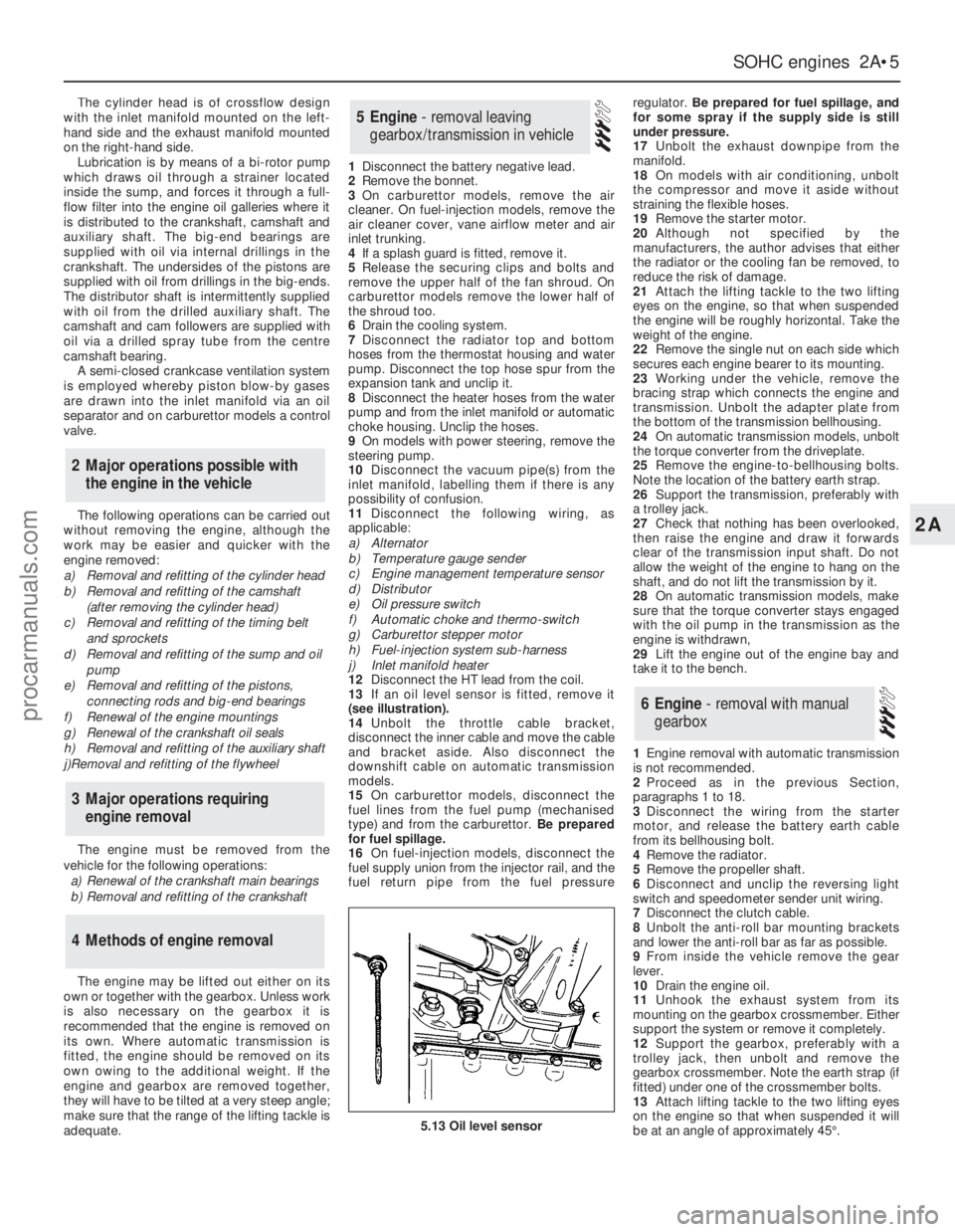
13If an oil level sensor is fitted, remove it
(see illustration).
14Unbolt the throttle cable bracket,
disconnect the inner cable and move the cable
and bracket aside. Also disconnect the
downshift cable on automatic transmission
models.
15On carburettor models, disconnect the
fuel lines from the fuel pump (mechanised
type) and from the carburettor. Be prepared
for fuel spillage.
16On fuel-injection models, disconnect the
fuel supply union from the injector rail, and the
fuel return pipe from the fuel pressureregulator. Be prepared for fuel spillage, and
for some spray if the supply side is still
under pressure.
17Unbolt the exhaust downpipe from the
manifold.
18On models with air conditioning, unbolt
the compressor and move it aside without
straining the flexible hoses.
19Remove the starter motor.
20Although not specified by the
manufacturers, the author advises that either
the radiator or the cooling fan be removed, to
reduce the risk of damage.
21Attach the lifting tackle to the two lifting
eyes on the engine, so that when suspended
the engine will be roughly horizontal. Take the
weight of the engine.
22Remove the single nut on each side which
secures each engine bearer to its mounting.
23Working under the vehicle, remove the
bracing strap which connects the engine and
transmission. Unbolt the adapter plate from
the bottom of the transmission bellhousing.
24On automatic transmission models, unbolt
the torque converter from the driveplate.
25Remove the engine-to-bellhousing bolts.
Note the location of the battery earth strap.
26Support the transmission, preferably with
a trolley jack.
27Check that nothing has been overlooked,
then raise the engine and draw it forwards
clear of the transmission input shaft. Do not
allow the weight of the engine to hang on the
shaft, and do not lift the transmission by it.
28On automatic transmission models, make
sure that the torque converter stays engaged
with the oil pump in the transmission as the
engine is withdrawn,
29Lift the engine out of the engine bay and
take it to the bench.
1Engine removal with automatic transmission
is not recommended.
2Proceed as in the previous Section,
paragraphs 1 to 18.
3Disconnect the wiring from the starter
motor, and release the battery earth cable
from its bellhousing bolt.
4Remove the radiator.
5Remove the propeller shaft.
6Disconnect and unclip the reversing light
switch and speedometer sender unit wiring.
7Disconnect the clutch cable.
8Unbolt the anti-roll bar mounting brackets
and lower the anti-roll bar as far as possible.
9From inside the vehicle remove the gear
lever.
10Drain the engine oil.
11Unhook the exhaust system from its
mounting on the gearbox crossmember. Either
support the system or remove it completely.
12Support the gearbox, preferably with a
trolley jack, then unbolt and remove the
gearbox crossmember. Note the earth strap (if
fitted) under one of the crossmember bolts.
13Attach lifting tackle to the two lifting eyes
on the engine so that when suspended it will
be at an angle of approximately 45°.
6Engine - removal with manual
gearbox
5Engine - removal leaving
gearbox/transmission in vehicle
4Methods of engine removal
3Major operations requiring
engine removal
2Major operations possible with
the engine in the vehicle
SOHCengines 2A•5
2A
5.13 Oil level sensor
procarmanuals.com
Page 30 of 255
the tensioner to release the load on the belt
and slip the belt off the camshaft sprocket. Do
not kink the belt, or get oil or grease on it.
5Remove the ten bolts which secure the
rocker cover, noting the location of the
different shapes of reinforcing plates. Remove
the cover and gasket.
6Using a Torx key, slacken the cylinder head
bolts half a turn at a time in the reverse of the
tightening sequence.7With the bolts removed, lift the cylinder
head from the block. If it is stuck, tap it with a
wooden or plastic mallet to free it. Do not
lever between the head and block, or the
mating surfaces may be damaged. Do not
crank the engine to free the head, as the
pistons may contact the valves.
8Place the cylinder head on a couple of
wooden blocks so that the protruding valves
are not damaged.
1Remove the cylinder head as described in
the previous Section.
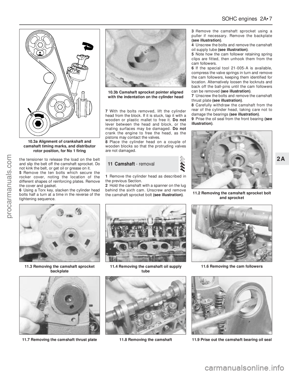
2Hold the camshaft with a spanner on the lug
behind the sixth cam. Unscrew and remove
the camshaft sprocket bolt (see illustration).3Remove the camshaft sprocket using a
puller if necessary. Remove the backplate
(see illustration).
4Unscrew the bolts and remove the camshaft
oil supply tube (see illustration).
5Note how the cam follower retaining spring
clips are fitted, then unhook them from the
cam followers.
6If the special tool 21-005-A is available,
compress the valve springs in turn and remove
the cam followers, keeping them identified for
location. Alternatively loosen the locknuts and
back off the ball-pins until the cam followers
can be removed (see illustration).
7Unscrew the bolts and remove the camshaft
thrust plate (see illustration).
8Carefully withdraw the camshaft from the
rear of the cylinder head, taking care not to
damage the bearings (see illustration).
9Prise the oil seal from the front bearing (see
illustration).11Camshaft - removal
SOHCengines 2A•7
2A
10.3a Alignment of crankshaft and
camshaft timing marks, and distributor
rotor position, for No 1 firing
10.3b Camshaft sprocket pointer aligned
with the indentation on the cylinder head
11.6 Removing the cam followers
11.2 Removing the camshaft sprocket bolt
and sprocket
11.3 Removing the camshaft sprocket
backplate11.4 Removing the camshaft oil supply
tube
11.9 Prise out the camshaft bearing oil seal11.7 Removing the camshaft thrust plate11.8 Removing the camshaft
procarmanuals.com
Page 31 of 255
1Remove the camshaft as described in the
previous Section. (If tool 21-005-A is available,
leave the camshaft in place until the valves
have been removed).
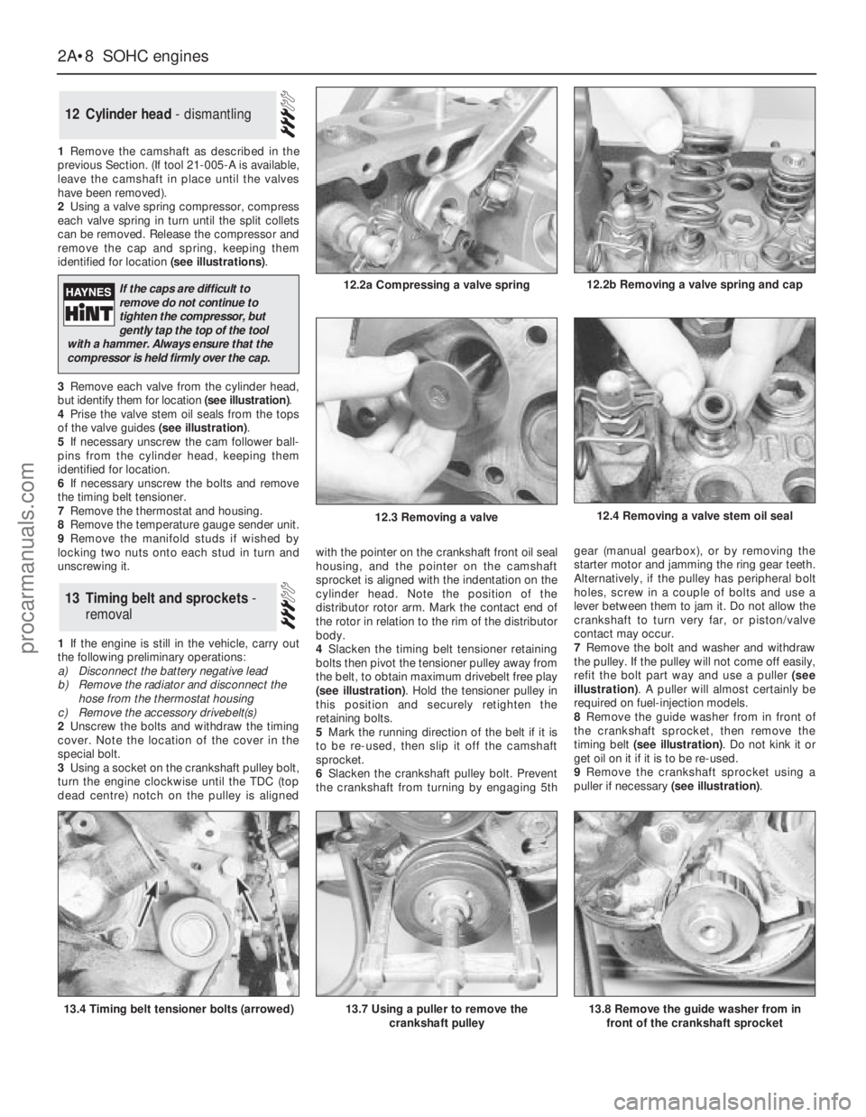
2Using a valve spring compressor, compress
each valve spring in turn until the split collets
can be removed. Release the compressor and
remove the cap and spring, keeping them
identified for location (see illustrations).
3Remove each valve from the cylinder head,
but identify them for location (see illustration).
4Prise the valve stem oil seals from the tops
of the valve guides (see illustration).
5If necessary unscrew the cam follower ball-
pins from the cylinder head, keeping them
identified for location.
6If necessary unscrew the bolts and remove
the timing belt tensioner.
7Remove the thermostat and housing.
8Remove the temperature gauge sender unit.
9Remove the manifold studs if wished by
locking two nuts onto each stud in turn and
unscrewing it.
1If the engine is still in the vehicle, carry out
the following preliminary operations:
a)Disconnect the battery negative lead
b)Remove the radiator and disconnect the
hose from the thermostat housing
c)Remove the accessory drivebelt(s)
2Unscrew the bolts and withdraw the timing
cover. Note the location of the cover in the
special bolt.
3Using a socket on the crankshaft pulley bolt,
turn the engine clockwise until the TDC (top
dead centre) notch on the pulley is alignedwith the pointer on the crankshaft front oil seal
housing, and the pointer on the camshaft
sprocket is aligned with the indentation on the
cylinder head. Note the position of the
distributor rotor arm. Mark the contact end of
the rotor in relation to the rim of the distributor
body.
4Slacken the timing belt tensioner retaining
bolts then pivot the tensioner pulley away from
the belt, to obtain maximum drivebelt free play
(see illustration). Hold the tensioner pulley in
this position and securely retighten the
retaining bolts.
5Mark the running direction of the belt if it is
to be re-used, then slip it off the camshaft
sprocket.
6Slacken the crankshaft pulley bolt. Prevent
the crankshaft from turning by engaging 5thgear (manual gearbox), or by removing the
starter motor and jamming the ring gear teeth.
Alternatively, if the pulley has peripheral bolt
holes, screw in a couple of bolts and use a
lever between them to jam it. Do not allow the
crankshaft to turn very far, or piston/valve
contact may occur.
7Remove the bolt and washer and withdraw
the pulley. If the pulley will not come off easily,
refit the bolt part way and use a puller (see
illustration). A puller will almost certainly be
required on fuel-injection models.
8Remove the guide washer from in front of
the crankshaft sprocket, then remove the
timing belt (see illustration). Do not kink it or
get oil on it if it is to be re-used.
9Remove the crankshaft sprocket using a
puller if necessary (see illustration).
13Timing belt and sprockets -
removal
12Cylinder head - dismantling
2A•8SOHCengines
12.2a Compressing a valve spring
13.4 Timing belt tensioner bolts (arrowed)13.7 Using a puller to remove the
crankshaft pulley
12.4 Removing a valve stem oil seal
13.8 Remove the guide washer from in
front of the crankshaft sprocket
12.2b Removing a valve spring and cap
12.3 Removing a valve
If the caps are difficult to
remove do not continue to
tighten the compressor, but
gently tap the top of the tool
with a hammer. Always ensure that the
compressor is held firmly over the cap.
procarmanuals.com