1985 FORD GRANADA cooling
[x] Cancel search: coolingPage 47 of 255
manifold. Piston blow-by gases are drawn
through the oil separator and the vent valve to
the inlet manifold. The blow-by gases are then
drawn into the engine together with the fuel/air
mixture. Refer to Chapter 1 for maintenance of
the system.
The following operations can be carried out
without removing the engine from the vehicle.
a)Removal of the camshafts.
b)Removal and servicing of the cylinder
head.
c)Removal of the timing chain and
sprockets.
d)Removal of the oil pump.
e)Removal of the sump.
f)Removal of the pistons and connecting
rods.
g)Removal of the big-end bearings.
h)Removal of the engine mountings.
i)Removal of the clutch and flywheel.
j)Removal of the crankshaft front and rear
oil seals.
The following operations can only be carried
out after removing the engine from the vehicle.
a)Removal of the crankshaft main bearings.
b)Removal of the crankshaft.
Note: A hoist and lifting tackle will be required
to lift the engine out of the vehicle.
1Disconnect the battery negative lead.
2Remove the bonnet.
3On carburettor models, remove the air cleaner.
4On fuel-injection models, remove the air
inlet hose, plenum chamber and air cleaner lid
as an assembly.
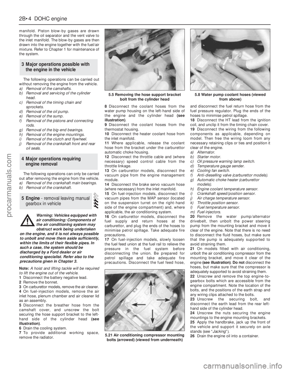
5Disconnect the breather hose from the
camshaft cover, and unscrew the bolt
securing the hose support bracket to the left-
hand side of the cylinder head (see
illustration).
6Drain the cooling system.
7To provide additional working space,
remove the radiator.8Disconnect the coolant hoses from the
water pump housing on the left-hand side of
the engine and the cylinder head (see
illustration).
9Disconnect the coolant hoses from the
thermostat housing.
10Disconnect the heater coolant hose from
the inlet manifold.
11Where applicable, release the coolant
hose from the bracket under the carburettor
automatic choke housing.
12Disconnect the throttle cable and (where
necessary) speed control cable from the
throttle linkage.
13On carburettor models, disconnect the
vacuum pipe from the engine management
module.
14Disconnect the brake servo vacuum hose
(where necessary) from the inlet manifold.
15On fuel-injection models, disconnect the
vacuum pipes from the MAP sensor (located
on the suspension turret on the right-hand
side of the engine compartment) and, where
applicable, the air conditioning system.
16On carburettor models, disconnect the
fuel supply and return hoses at the
carburettor, and plug the ends of the hoses to
minimise petrol spillage. Take adequate fire
precautions.
17On fuel-injection models, slowly loosen
the fuel feed union at the fuel rail to relieve the
pressure in the fuel system before
disconnecting the union. Be prepared for
petrol spillage and take adequate fire
precautions. Disconnect the fuel feed hose,and disconnect the fuel return hose from the
fuel pressure regulator. Plug the ends of the
hoses to minimise petrol spillage.
18Disconnect the HT lead from the ignition
coil, and unclip it from the timing chain cover.
19Disconnect the wiring from the following
components as applicable, depending on
model. Then free the wiring loom from any
necessary retaining clips or ties and position it
clear of the engine.
a)Alternator.
b)Starter motor.
c)Oil pressure warning lamp switch.
d)Temperature gauge sender.
e)Cooling fan switch.
f)Anti-dieselling valve (carburettor models).
g)Automatic choke heater (carburettor
models).
h)Engine coolant temperature sensor.
i)Crankshaft speed/position sensor.
j)Air charge temperature sensor.
k)Throttle position sensor.
l)Fuel temperature sensor.
m)Fuel injectors.
20Remove the water pump/alternator
drivebelt, then unbolt the power steering
pump from the mounting bracket and move it
clear of the engine. Note that there is no need
to disconnect the fluid hoses, but make sure
that the pump is adequately supported to
avoid straining them.
21On models fitted with air conditioning,
unbolt the air conditioning compressor from the
mounting bracket, and move it clear of the
engine (see illustration). Do notdisconnect the
hoses, but make sure that the compressor is
adequately supported to avoid straining them.
22Unscrew and remove the top engine-to-
gearbox bolts which are accessible from the
engine compartment. Note the location of the
bolts, and the positions of the earth strap and
any wiring clips attached to the bolts.
23Unscrew the securing bolt, and
disconnect the earth lead from the rear left-
hand side of the cylinder head.
24Unscrew the nuts securing the engine
mountings to the engine mounting brackets.
25Apply the handbrake, jack up the front of
the vehicle and support it securely on axle
stands (see “Jacking”).
26Drain the engine oil into a container.
5Engine - removal leaving manual
gearbox in vehicle
4Major operations requiring
engine removal
3Major operations possible with
the engine in the vehicle
2B•4DOHCengine
5.5 Removing the hose support bracket
bolt from the cylinder head5.8 Water pump coolant hoses (viewed
from above)
5.21 Air conditioning compressor mounting
bolts (arrowed) (viewed from underneath)
Warning: Vehicles equipped with
air conditioning: Components of
the air conditioning system may
obstruct work being undertaken
on the engine, and it is not always possible
to unbolt and move them aside sufficiently,
within the limits of their flexible pipes. In
such a case, the system should be
discharged by a Ford dealer or air
conditioning specialist. Refer also to the
precautions given in Chapter 3.
procarmanuals.com
Page 50 of 255
21Working through the starter motor
aperture, unscrew the four torque converter-
to-driveplate nuts. It will be necessary to turn
the crankshaft using a spanner on the
crankshaft pulley bolt in order to gain access
to each nut in turn through the aperture.
22Where applicable, remove the bolt
securing the transmission fluid dipstick tube to
the left-hand side of the cylinder block.
23Unscrew the engine-to-transmission bolts,
noting the locations of the bolts, and the
positions of the earth strap and any wiring
clips attached to the bolts. Recover any shims
fitted between the sump and the transmission
when removing the lower engine-to-
transmission bolts.
24Unscrew the bolt from the engine adapter
plate and, where applicable, pull the blanking
plug from the adapter plate.
25Pull the engine and the transmission apart,
ensuring that the torque converter is held firmly
in place in the transmission housing, otherwise
it could fall out resulting in fluid spillage and
possible damage. It may be necessary to rock
the units slightly to separate them.
1Reverse the procedure described in
paragraphs 1 to 40 ofSection 5, noting the
following points.
2Before attempting to refit the engine, check
that the clutch friction disc is centralised.
3Check that the clutch release arm and
bearing are correctly fitted, and lightly grease
the input shaft splines.
4Check that the engine adapter plate is
correctly positioned on the locating dowels. If
necessary, a cable-tie can be used to
temporarily secure the adapter plate in
position on the cylinder block using one of the
engine-to-gearbox bolt holes.
5If shims were fitted between the sump and
the gearbox, refit them in their original
locations when mating the engine to the
gearbox. If the engine has been overhauled,
where applicable fit the relevant shims as
calculated during engine reassembly .
6Reconnect the clutch cable to the release arm,
ensuring that it is routed as noted during removal.
7Ensure that the roadwheels and the steering
wheel are in the straight-ahead position then
align the marks made on removal and reconnect
the intermediate shaft to the steering gearing.
Tighten the clamp bolt to the specified torque.
8Refit the exhaust downpipe.
9Fill the engine with the correct grade and
quantity of oil.
10Check the throttle cable adjustment. Where
necessary, also adjust the speed control cable
in the same way so that there is only a small
amount of slack present in the cable.
11Reconnect the coolant hoses to the water
pump housing.
12Fill the cooling system .
13Tighten all fixings to the specified torque,
where applicable.1Reverse the procedure described in Section 6,
noting the following points.
2Check that the engine adapter plate is
correctly positioned on the locating dowels. If
necessary, a cable-tie can be used to
temporarily secure the adapter plate in
position on the cylinder block using one of the
engine-to-transmission bolt holes.
3As the torque converter is only loosely
engaged in the transmission, care must be taken
to prevent the torque converter from falling out
forwards. When the torque converter hub is fully
engaged with the fluid pump drivegear in the
transmission, distance A (see illustration 2.20 in
Chapter 7B)must be as specified. Incorrect
installation of the torque converter will result in
damageto the transmission.
4If shims were fitted between the sump and
the transmission, refit them in their original
locations when mating the engine to the
transmission. If the engine has been
overhauled, where applicable fit the relevant
shims as calculated during engine reassembly.
5As the engine is installed, guide the torque
converter studs through the holes in the
driveplate. When the engine is positioned flush
with the engine adapter plate and the
transmission housing, check that the torque
converter is free to move axially a small
amount before refitting and tightening the
engine-to-transmission bolts.
6Do not tighten the torque converter-to-
driveplate nuts until the lower engine-to-
transmission bolts have been fitted and
tightened.
7Ensure that the roadwheels and the steering
wheel are in the straight-ahead position then
align the marks made on removal and
reconnect the intermediate shaft to the
steering gearing. Tighten the clamp bolt to the
specified torque.
8Refit the exhaust downpipe.
9Fill the engine with the correct grade and
quantity of oil.
10Check the throttle cable adjustment. Where
necessary, also adjust the speed control cable
in the same way so that there is only a small
amount of slack present in the cable.
11Reconnect the coolant hoses to the water
pump housing.
12Fill the cooling system.
13Tighten all fixings to the specified torque,
where applicable.
1Reverse the procedure described in Section 7,
noting the following points.
2Before attempting to reconnect the engine
to the gearbox, check that the clutch friction
disc is centralised.
3Check that the clutch release arm andbearing are correctly fitted, and lightly grease
the input shaft splines.
4Check that the engine adapter plate is
correctly positioned on the locating dowels. If
necessary, a cable-tie can be used to
temporarily secure the adapter plate in
position on the cylinder block using one of the
engine-to-gearbox bolt holes.
5If shims were fitted between the sump and
the gearbox, refit them in their original
locations when mating the engine to the
gearbox. If the engine has been overhauled,
where applicable fit the relevant shims as
calculated during engine reassembly.
6Ensure that the roadwheels and the steering
wheel are in the straight-ahead position then
align the marks made on removal and
reconnect the intermediate shaft to the
steering gearing. Tighten the clamp bolt to the
specified torque.
7Reconnect the clutch cable to the release
arm, ensuring that it is routed as noted during
removal.
8Refit the propeller shaft.
9Refit the exhaust system.
10Fill the engine with the correct grade and
quantity of oil.
11Check the throttle cable adjustment. Where
necessary, also adjust the speed control cable
in the same way so that there is only a small
amount of slack present in the cable.
12Reconnect the coolant hoses to the water
pump housing.
13Fill the cooling system.
14Check and if necessary top-up the
gearbox oil level.
15Tighten all fixings to the specified torque,
where applicable.
1Reverse the procedure described in Section 8,
noting the following points.
2Check that the engine adapter plate is
correctly positioned on the locating dowels. If
necessary, a cable-tie can be used to
temporarily secure the adapter plate in
position on the cylinder block using one of the
engine-to-transmission bolt holes.
3As the torque converter is only loosely
engaged in the transmission, care must be taken
to prevent the torque converter from falling out
forwards. When the torque converter hub is fully
engaged with the fluid pump drivegear in the
transmission, distance A (see illustration 2.20 in
Chapter 7B)must be as specified. Incorrect
installation of the torque converter will result in
damage to the transmission.
4If shims were fitted between the sump and
the transmission, refit them in their original
locations when mating the engine to the
transmission. If the engine has been
overhauled, where applicable fit the relevant
shims as calculated during engine reassembly.
5As the engine and transmission are mated
12Engine/automatic
transmission assembly -
reconnection and refitting
11Engine/manual gearbox
assembly - reconnection and
refitting
10Engine - refitting (automatic
transmission in vehicle)
9Engine - refitting (manual
gearbox in vehicle)
DOHCengine 2B•7
2B
procarmanuals.com
Page 51 of 255
together, guide the torque converter studs
through the holes in the driveplate. When the
engine is positioned flush with the engine
adapter plate and the transmission housing,
check that the torque converter is free to move
axially a small amount before refitting and
tightening the engine-to-transmission bolts.
6Do not tighten the torque converter-to-
driveplate nuts until the lower engine-to-
transmission bolts have been fitted and
tightened.
7Ensure that the roadwheels and the steering
wheel are in the straight-ahead position then
align the marks made on removal and
reconnect the intermediate shaft to the
steering gearing. Tighten the clamp bolt to the
specified torque.
8Reconnect the selector rod and adjust as
described in Chapter 7, PartB.
9Refit the propeller shaft.
10Refit the exhaust system.
11Fill the engine with the correct grade and
quantity of oil.
12Check the throttle cable adjustment. Where
necessary, also adjust the speed control cable
in the same way so that there is only a small
amount of slack present in the cable.
13Reconnect the coolant hoses to the water
pump housing.
14Fill the cooling system.
15Check and if necessary top-up the
transmission fluid level.
16Tighten all fixings to the specified torque,
where applicable.
Proceed as described in Part A, Section 23
of this Chapter but note that on certain
models, it may be necessary to unbolt the
engine mounting brackets from the cylinder
block to allow sufficient clearance to remove
the mountings.
1Refer to Part A, Section 8 of this Chapter,
paragraphs 1 to 8 inclusive.
2A selection of splined and Torx sockets will
be required to remove many of the bolts when
dismantling the engine.
3Before dismantling the main engine
components, the following externally mounted
ancillary components can be removed.
a)Inlet manifold (and carburettor, where
applicable).
b)Exhaust manifold.
c)Alternator.
d)Water pump, and thermostat.
e)Water pump/alternator drivebelt tensioner.
f)Distributor cap, HT leads and spark plugs.
g)Oil pressure warning lamp switch.
h)Crankshaft speed/position sensor.
i)Oil filter.
j)Dipstick.
k)Engine mounting brackets (if not already
done).
l)Crankcase ventilation pipe and hoses.m)Clutch.
n)Alternator mounting bracket.
o)Air conditioning compressor mounting
bracket (where applicable).
p)Engine lifting brackets.
Note: A puller will be required to remove the
crankshaft pulley. A new crankshaft pulley bolt,
a new timing chain tensioner plunger
assembly, new upper and lower timing chain
cover gaskets and a new camshaft cover
gasket and reinforcing sleeve sealing rings
must be used on refitting.
1If the engine is in the car, carry out thefollowing operations.
a)Disconnect the battery negative lead.
b)To improve access, remove the radiator. It
will be difficult to remove the crankshaft
pulley with the radiator in place.
c)On carburettor models, remove the air
cleaner.
d)On fuel-injection models, remove the air
inlet hose, plenum chamber and air
cleaner lid as an assembly.
e)Disconnect the breather hose from the
camshaft cover.
f)Remove the distributor cap and HT leads,
and the rotor arm and housing.
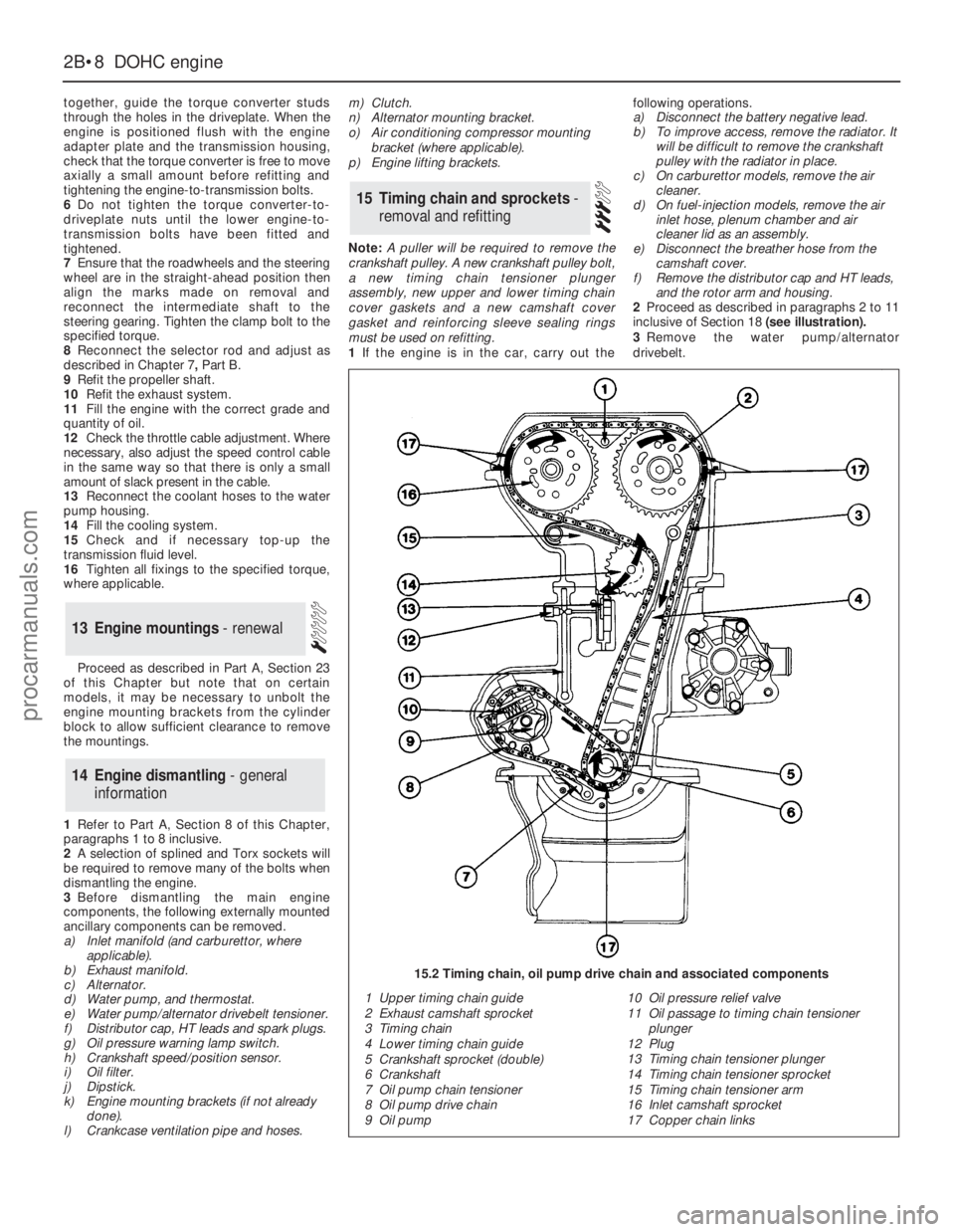
2Proceed as described in paragraphs 2 to 11
inclusive of Section 18 (see illustration).
3Remove the water pump/alternator
drivebelt.
15Timing chain and sprockets -
removal and refitting
14Engine dismantling - general
information
13Engine mountings - renewal
2B•8DOHCengine
1 Upper timing chain guide
2 Exhaust camshaft sprocket
3 Timing chain
4 Lower timing chain guide
5 Crankshaft sprocket (double)
6 Crankshaft
7 Oil pump chain tensioner
8 Oil pump drive chain
9 Oil pump10 Oil pressure relief valve
11 Oil passage to timing chain tensioner
plunger
12 Plug
13 Timing chain tensioner plunger
14 Timing chain tensioner sprocket
15 Timing chain tensioner arm
16 Inlet camshaft sprocket
17 Copper chain links
15.2 Timing chain, oil pump drive chain and associated components
procarmanuals.com
Page 53 of 255
prevent the chain from dropping into the
timing case, as during removal.
18Locate the double chain sprocket loosely
over the end of the crankshaft (larger sprocket
nearest the crankcase), with the timing mark
pointing vertically down.
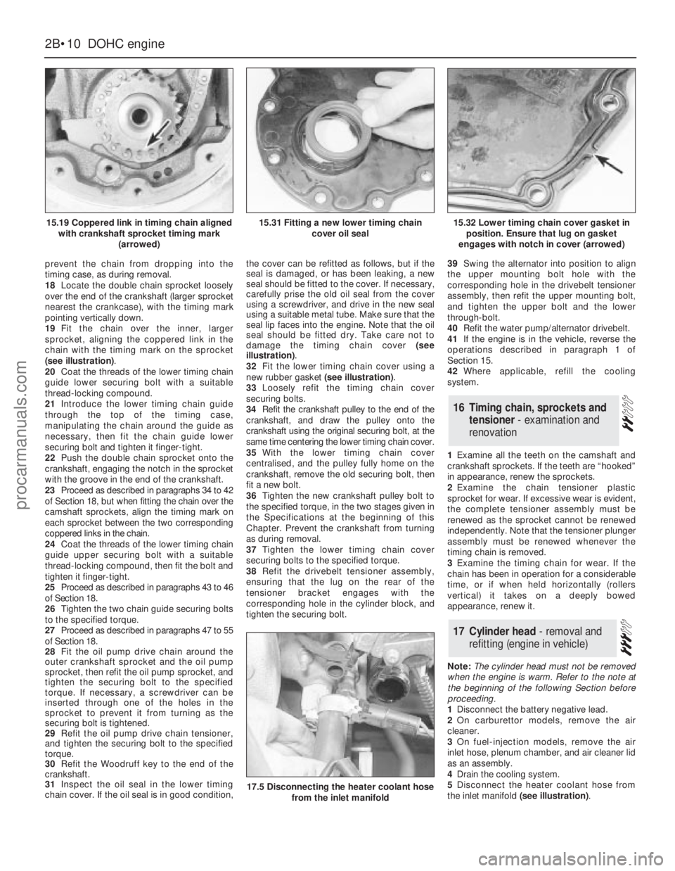
19Fit the chain over the inner, larger
sprocket, aligning the coppered link in the
chain with the timing mark on the sprocket
(see illustration).
20Coat the threads of the lower timing chain
guide lower securing bolt with a suitable
thread-locking compound.
21Introduce the lower timing chain guide
through the top of the timing case,
manipulating the chain around the guide as
necessary, then fit the chain guide lower
securing bolt and tighten it finger-tight.
22Push the double chain sprocket onto the
crankshaft, engaging the notch in the sprocket
with the groove in the end of the crankshaft.
23Proceed as described in paragraphs 34 to 42
of Section 18, but when fitting the chain over the
camshaft sprockets, align the timing mark on
each sprocket between the two corresponding
coppered links in the chain.
24Coat the threads of the lower timing chain
guide upper securing bolt with a suitable
thread-locking compound, then fit the bolt and
tighten it finger-tight.
25Proceed as described in paragraphs 43 to 46
of Section 18.
26Tighten the two chain guide securing bolts
to the specified torque.
27Proceed as described in paragraphs 47 to 55
of Section 18.
28Fit the oil pump drive chain around the
outer crankshaft sprocket and the oil pump
sprocket, then refit the oil pump sprocket, and
tighten the securing bolt to the specified
torque. If necessary, a screwdriver can be
inserted through one of the holes in the
sprocket to prevent it from turning as the
securing bolt is tightened.
29Refit the oil pump drive chain tensioner,
and tighten the securing bolt to the specified
torque.
30Refit the Woodruff key to the end of the
crankshaft.
31Inspect the oil seal in the lower timing
chain cover. If the oil seal is in good condition,the cover can be refitted as follows, but if the
seal is damaged, or has been leaking, a new
seal should be fitted to the cover. If necessary,
carefully prise the old oil seal from the cover
using a screwdriver, and drive in the new seal
using a suitable metal tube. Make sure that the
seal lip faces into the engine. Note that the oil
seal should be fitted dry. Take care not to
damage the timing chain cover (see
illustration).
32Fit the lower timing chain cover using a
new rubber gasket (see illustration).
33Loosely refit the timing chain cover
securing bolts.
34Refit the crankshaft pulley to the end of the
crankshaft, and draw the pulley onto the
crankshaft using the original securing bolt, at the
same time centering the lower timing chain cover.
35With the lower timing chain cover
centralised, and the pulley fully home on the
crankshaft, remove the old securing bolt, then
fit a new bolt.
36Tighten the new crankshaft pulley bolt to
the specified torque, in the two stages given in
the Specifications at the beginning of this
Chapter. Prevent the crankshaft from turning
as during removal.
37Tighten the lower timing chain cover
securing bolts to the specified torque.
38Refit the drivebelt tensioner assembly,
ensuring that the lug on the rear of the
tensioner bracket engages with the
corresponding hole in the cylinder block, and
tighten the securing bolt.39Swing the alternator into position to align
the upper mounting bolt hole with the
corresponding hole in the drivebelt tensioner
assembly, then refit the upper mounting bolt,
and tighten the upper bolt and the lower
through-bolt.
40Refit the water pump/alternator drivebelt.
41If the engine is in the vehicle, reverse the
operations described in paragraph 1 of
Section 15.
42Where applicable, refill the cooling
system.
1Examine all the teeth on the camshaft and
crankshaft sprockets. If the teeth are “hooked”
in appearance, renew the sprockets.
2Examine the chain tensioner plastic
sprocket for wear. If excessive wear is evident,
the complete tensioner assembly must be
renewed as the sprocket cannot be renewed
independently.Note that the tensioner plunger
assembly must be renewed whenever the
timing chain is removed.
3Examine the timing chain for wear. If the
chain has been in operation for a considerable
time, or if when held horizontally (rollers
vertical) it takes on a deeply bowed
appearance, renew it.
Note: The cylinder head must not be removed
when the engine is warm. Refer to the note at
the beginning of the following Section before
proceeding.
1Disconnect the battery negative lead.
2On carburettor models, remove the air
cleaner.
3On fuel-injection models, remove the air
inlet hose, plenum chamber, and air cleaner lid
as an assembly.
4Drain the cooling system.
5Disconnect the heater coolant hose from
the inlet manifold (see illustration).
17Cylinder head - removal and
refitting (engine in vehicle)
16Timing chain, sprockets and
tensioner - examination and
renovation
2B•10DOHCengine
15.19 Coppered link in timing chain aligned
with crankshaft sprocket timing mark
(arrowed)
17.5 Disconnecting the heater coolant hose
from the inlet manifold
15.31 Fitting a new lower timing chain
cover oil seal15.32 Lower timing chain cover gasket in
position. Ensure that lug on gasket
engages with notch in cover (arrowed)
procarmanuals.com
Page 54 of 255
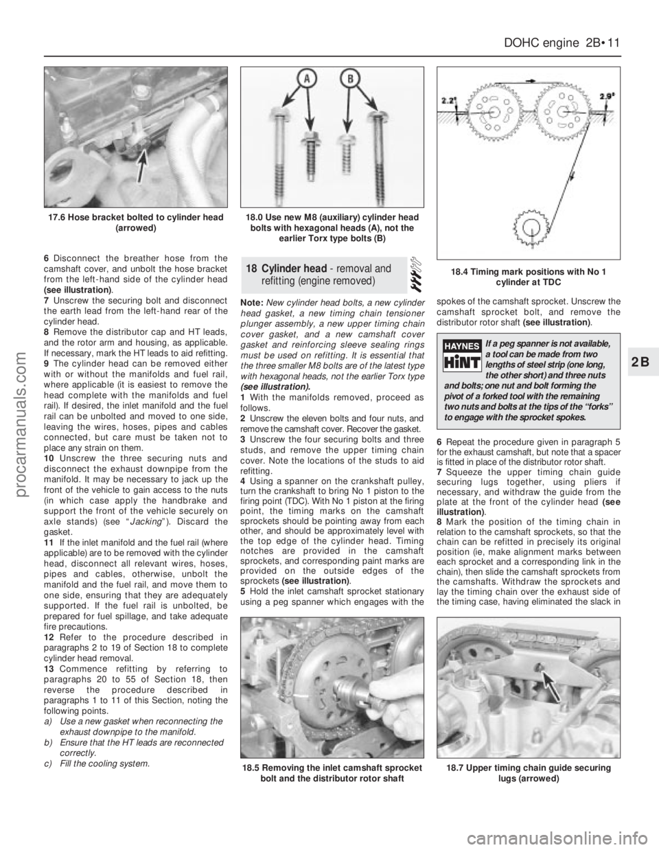
6Disconnect the breather hose from the
camshaft cover, and unbolt the hose bracket
from the left-hand side of the cylinder head
(see illustration).
7Unscrew the securing bolt and disconnect
the earth lead from the left-hand rear of the
cylinder head.
8Remove the distributor cap and HT leads,
and the rotor arm and housing, as applicable.
If necessary, mark the HT leads to aid refitting.
9The cylinder head can be removed either
with or without the manifolds and fuel rail,
where applicable (it is easiest to remove the
head complete with the manifolds and fuel
rail). If desired, the inlet manifold and the fuel
rail can be unbolted and moved to one side,
leaving the wires, hoses, pipes and cables
connected, but care must be taken not to
place any strain on them.
10Unscrew the three securing nuts and
disconnect the exhaust downpipe from the
manifold. It may be necessary to jack up the
front of the vehicle to gain access to the nuts
(in which case apply the handbrake and
support the front of the vehicle securely on
axle stands) (see “Jacking”). Discard the
gasket.
11If the inlet manifold and the fuel rail (where
applicable) are to be removed with the cylinder
head, disconnect all relevant wires, hoses,
pipes and cables, otherwise, unbolt the
manifold and the fuel rail, and move them to
one side, ensuring that they are adequately
supported. If the fuel rail is unbolted, be
prepared for fuel spillage, and take adequate
fire precautions.
12Refer to the procedure described in
paragraphs 2 to 19 of Section 18 to complete
cylinder head removal.
13Commence refitting by referring to
paragraphs 20 to 55 of Section 18, then
reverse the procedure described in
paragraphs 1 to 11 of this Section, noting the
following points.
a)Use a new gasket when reconnecting the
exhaust downpipe to the manifold.
b)Ensure that the HT leads are reconnected
correctly.
c)Fill the cooling system.Note: New cylinder head bolts, a new cylinder
head gasket, a new timing chain tensioner
plunger assembly, a new upper timing chain
cover gasket, and a new camshaft cover
gasket and reinforcing sleeve sealing rings
must be used on refitting. It is essential that
the three smaller M8 bolts are of the latest type
with hexagonal heads, not the earlier Torx type
(see illustration).
1With the manifolds removed, proceed as
follows.
2Unscrew the eleven bolts and four nuts, and
remove the camshaft cover. Recover the gasket.
3Unscrew the four securing bolts and three
studs, and remove the upper timing chain
cover. Note the locations of the studs to aid
refitting.
4Using a spanner on the crankshaft pulley,
turn the crankshaft to bring No 1 piston to the
firing point (TDC). With No 1 piston at the firing
point, the timing marks on the camshaft
sprockets should be pointing away from each
other, and should be approximately level with
the top edge of the cylinder head. Timing
notches are provided in the camshaft
sprockets, and corresponding paint marks are
provided on the outside edges of the
sprockets (see illustration).
5Hold the inlet camshaft sprocket stationary
using a peg spanner which engages with thespokes of the camshaft sprocket. Unscrew the
camshaft sprocket bolt, and remove the
distributor rotor shaft (see illustration).
6Repeat the procedure given in paragraph 5
for the exhaust camshaft, but note that a spacer
is fitted in place of the distributor rotor shaft.
7Squeeze the upper timing chain guide
securing lugs together, using pliers if
necessary, and withdraw the guide from the
plate at the front of the cylinder head (see
illustration).
8Mark the position of the timing chain in
relation to the camshaft sprockets, so that the
chain can be refitted in precisely its original
position (ie, make alignment marks between
each sprocket and a corresponding link in the
chain), then slide the camshaft sprockets from
the camshafts. Withdraw the sprockets and
lay the timing chain over the exhaust side of
the timing case, having eliminated the slack in18Cylinder head - removal and
refitting (engine removed)
DOHCengine 2B•11
2B
17.6 Hose bracket bolted to cylinder head
(arrowed)18.0 Use new M8 (auxiliary) cylinder head
bolts with hexagonal heads (A), not the
earlier Torx type bolts (B)
18.4 Timing mark positions with No 1
cylinder at TDC
18.5 Removing the inlet camshaft sprocket
bolt and the distributor rotor shaft18.7 Upper timing chain guide securing
lugs (arrowed)
If a peg spanner is not available,
a tool can be made from two
lengths of steel strip (one long,
the other short) and three nuts
and bolts; one nut and bolt forming the
pivot of a forked tool with the remaining
two nuts and bolts at the tips of the “forks”
to engage with the sprocket spokes.
procarmanuals.com
Page 68 of 255
meters and air inlet trunking. Also remove the
oil filler cap, which is connected to the
trunking by a crankcase ventilation hose.
5Release the securing clips and bolts and
remove the upper half of the fan shroud.
6Drain the cooling system and remove the
radiator.
7Disconnect the heater hoses from the
heater matrix and from the coolant outlet.
Unclip the hoses.
8Remove the fan and viscous clutch (where
fitted).
9Disconnect the following wiring:
a)Alternator
b)Temperature gauge sender
c)Engine management temperature sensor
d)Oil pressure switch
e)Idle speed control valve
f)Throttle position sensor
g)Injector nut-harness
h)Distributor multi-plug
i)Distributor-to-coil HT lead
10Disconnect the throttle cable. When
applicable, also disconnect the downshaft
cable or switch.
11Depressurise the fuel system and
disconnect the fuel supply and return lines
(see Chapter 4).
12Remove the steering pump and air
conditioning compressor drivebelts (as
applicable). Unbolt the steering pump and
compressor, move them aside within the limitsof their flexible hoses and support them by
wiring them to adjacent components.
13Remove the distributor cap and rotor.
14Remove the starter motor.
15Drain the engine oil. Unscrew the oil filter
with a strap or chain wrench and remove it; be
prepared for oil spillage.
16On manual gearbox models, disconnect
the clutch cable from the release lever.
17Unbolt the exhaust pipes from the
manifolds.
18On automatic transmission models, unbolt
the torque converter from the driveplate.
19Attach lifting tackle to the engine. If no
lifting eyes are fitted, pass ropes or chains
round the exhaust manifolds.
20Take the weight of the engine, then
remove the single nut on each side which
holds engine bearer to its mountings.
21From under the vehicle unbolt the engine
adapter plate from the bellhousing.
22Remove the engine-to-bellhousing bolts.
Also disconnect or unclip the battery negative
lead, the starter motor lead and the heat
shield.
23Support the transmission, preferably with
a trolley jack.
24Check that nothing has been overlooked,
then raise the engine and draw it forwards
clear of the transmission input shaft. Do not
allow the weight of the engine to hang on the
shaft, and do not lift the transmission by it.25With automatic transmission, make sure
that the torque converter stays engaged with
the oil pump in the transmission as the engine
is withdrawn.
26Lift the engine out of the engine bay and
take it to the bench.
2.4 & 2.9 litre engines
27The removal operations for these engines
are essentially as described for the 2.8 litre
version. Note the following points.
Coolant hoses
28Remove the hoses which run between the
thermostat housing and the water pump, and
the cooling system expansion tank.
29Remove the heater hoses which run
between the thermostat housing or coolant
distribution pipe and oil cooler (where fitted).
Vacuum hoses
30Disconnect the hose from the fuel
pressure regulator.
31Disconnect the hose from the plenum
chamber.
32Disconnect the hose from the throttle valve.
33Disconnect the hose from the T-piece
connector.
V6 engines 2C•7
2C
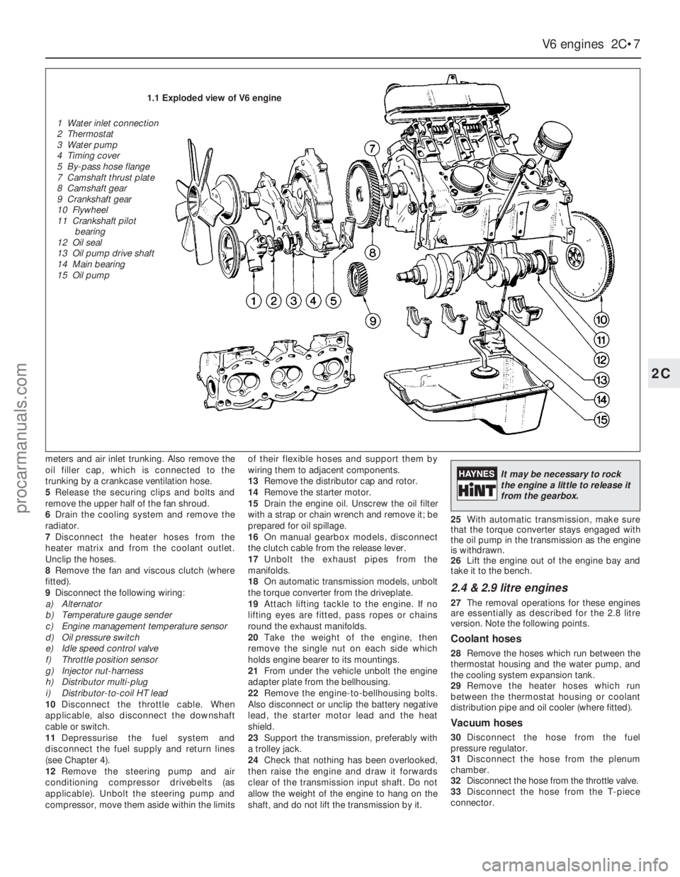
1.1 Exploded view of V6 engine
1 Water inlet connection
2 Thermostat
3 Water pump
4 Timing cover
5 By-pass hose flange
7 Camshaft thrust plate
8 Camshaft gear
9 Crankshaft gear
10 Flywheel
11 Crankshaft pilot
bearing
12 Oil seal
13 Oil pump drive shaft
14 Main bearing
15 Oil pump
It may be necessary to rock
the engine a little to release it
from the gearbox.
procarmanuals.com
Page 69 of 255
Other items
34Disconnect the throttle cable from the
operating lever and bracket.
35Disconnect the right-hand exhaust
downpipe from the manifold then remove the
starter motor, the oil filter, and disconnect the
left-hand exhaust downpipe, in that order.
Refer to Part A, Section 8, paragraphs 1 to 8
of this Chapter.
Cylinder head bolts on the V6 engine may
be conventional (hexagon-headed) or Torx
type. The appropriate Torx key will be needed
to deal with the latter.
Before dismantling the engine into its main
components, the following ancillaries can be
removed. The actual items removed, and the
sequence of removal, will depend on the work
to be done.
Distributor and bracket
Spark plugs
Inlet manifold and associated items
Exhaust manifolds
Clutch
Alternator and bracket
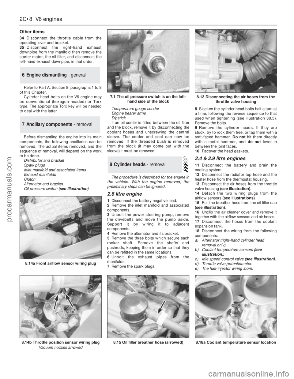
Oil pressure switch(see illustration) Temperature gauge sender
Engine bearer arms
Dipstick
If an oil cooler is fitted between the oil filter
and the block, remove it by disconnecting the
coolant hoses and unscrewing the central
sleeve. The cooler and seal can now be
removed. If the threaded bush is removed
from the block (it may come out with the
sleeve) it must be renewed.
The procedure is described for the engine in
the vehicle. With the engine removed, the
preliminary steps can be ignored.
2.8 litre engine
1Disconnect the battery negative lead.
2Remove the inlet manifold and associated
components.
3Unbolt the power steering pump, remove
the drivebelts and move the pump aside.
Support it by wiring it to adjacent
components.
4Remove the alternator and its bracket.
5Remove the three bolts which secure each
rocker shaft. Remove the shafts and
pushrods, keeping them in order so that they
can be refitted in the same locations.
6Unbolt the exhaust pipes from the
manifolds.
7Remove the spark plugs.8Slacken the cylinder head bolts half a turn at
a time, following the reverse sequence to that
used when tightening (see illustration 38.5).
Remove the bolts.
9Remove the cylinder heads. If they are
stuck, try to rock them free, or tap them with a
soft-faced hammer. Do nothit them directly
with a metal hammer, and do notlever in
between the joint faces.
10Recover the head gaskets.
2.4 & 2.9 litre engines
11Disconnect the battery and drain the
cooling system.
12Disconnect the radiator top hose and the
heater hose from the thermostat housing.
13Disconnect the air hoses from the throttle
valve housing (see illustration).
14Detach the two wiring plugs from the
airflow sensors (see illustrations).
15Pull the breather hose from the oil filler cap
(see illustration).
16Unclip the air cleaner cover and remove it
together with the airflow sensors and air hoses.
17Disconnect the hoses from the coolant
expansion tank.
18Disconnect the wiring from the following
components:
a)Alternator (right-hand cylinder head
removal only).
b)Coolant temperature sensors(see
illustration).
c)Idle speed control valve (see illustration).
d)Throttle valve potentiometer.
e)The fuel-injector wiring loom.8Cylinder heads - removal
7Ancillary components - removal
6Engine dismantling - general
2C•8V6 engines
7.1 The oil pressure switch is on the left-
hand side of the block
8.14b Throttle position sensor wiring plug
Vacuum nozzles arrowed
8.14a Front airflow sensor wiring plug
8.15 Oil filler breather hose (arrowed)8.18a Coolant temperature sensor location
8.13 Disconnecting the air hoses from the
throttle valve housing
procarmanuals.com
Page 71 of 255
4Remove the auxiliary drivebelts.
5Remove the fan and viscous clutch if fitted).
6Jam the crankshaft, either by engaging 5th
gear and applying the handbrake, or by
removing the starter motor and having an
assistant jam a screwdriver in the starter ring
gear teeth. Unbolt the crankshaft pulley. When
the pulley is secured to a vibration damper,
also remove the damper central bolt.
7Remove the pulley or damper, using a puller
if necessary.
8Disconnect the coolant hoses from the front
of the engine, including the water pump
bypass hose.
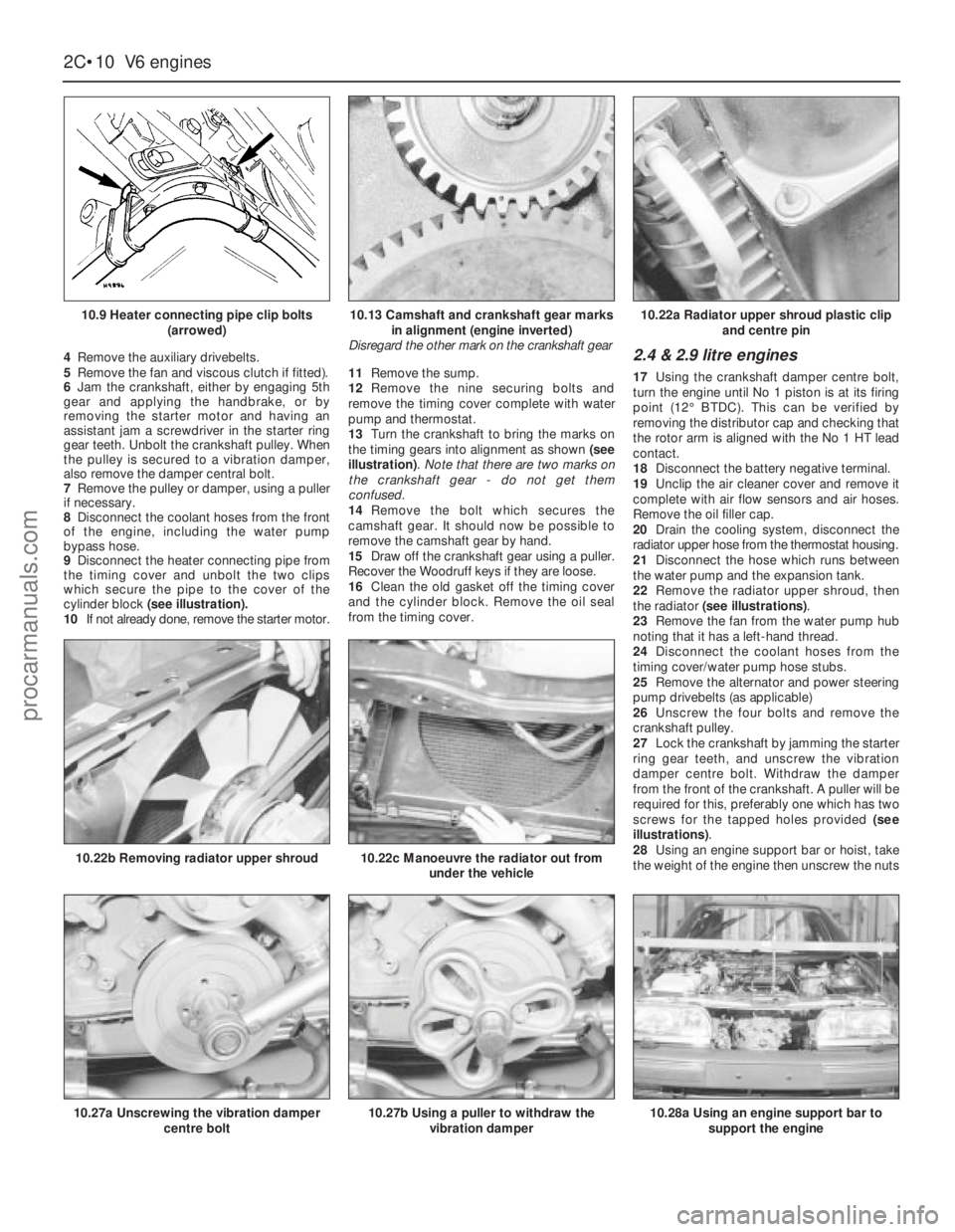
9Disconnect the heater connecting pipe from
the timing cover and unbolt the two clips
which secure the pipe to the cover of the
cylinder block (see illustration).
10If not already done, remove the starter motor.11Remove the sump.
12Remove the nine securing bolts and
remove the timing cover complete with water
pump and thermostat.
13Turn the crankshaft to bring the marks on
the timing gears into alignment as shown (see
illustration). Note that there are two marks on
the crankshaft gear - do not get them
confused.
14Remove the bolt which secures the
camshaft gear. It should now be possible to
remove the camshaft gear by hand.
15Draw off the crankshaft gear using a puller.
Recover the Woodruff keys if they are loose.
16Clean the old gasket off the timing cover
and the cylinder block. Remove the oil seal
from the timing cover.2.4 & 2.9 litre engines
17Using the crankshaft damper centre bolt,
turn the engine until No 1 piston is at its firing
point (12°BTDC). This can be verified by
removing the distributor cap and checking that
the rotor arm is aligned with the No 1 HT lead
contact.
18Disconnect the battery negative terminal.
19Unclip the air cleaner cover and remove it
complete with air flow sensors and air hoses.
Remove the oil filler cap.
20Drain the cooling system, disconnect the
radiator upper hose from the thermostat housing.
21Disconnect the hose which runs between
the water pump and the expansion tank.
22Remove the radiator upper shroud, then
the radiator (see illustrations).
23Remove the fan from the water pump hub
noting that it has a left-hand thread.
24Disconnect the coolant hoses from the
timing cover/water pump hose stubs.
25Remove the alternator and power steering
pump drivebelts (as applicable)
26Unscrew the four bolts and remove the
crankshaft pulley.
27Lock the crankshaft by jamming the starter
ring gear teeth, and unscrew the vibration
damper centre bolt. Withdraw the damper
from the front of the crankshaft. A puller will be
required for this, preferably one which has two
screws for the tapped holes provided (see
illustrations).
28Using an engine support bar or hoist, take
the weight of the engine then unscrew the nuts
2C•10V6 engines
10.9 Heater connecting pipe clip bolts
(arrowed)
10.27a Unscrewing the vibration damper
centre bolt
10.22b Removing radiator upper shroud10.22c Manoeuvre the radiator out from
under the vehicle
10.27b Using a puller to withdraw the
vibration damper10.28a Using an engine support bar to
support the engine
10.13 Camshaft and crankshaft gear marks
in alignment (engine inverted)
Disregard the other mark on the crankshaft gear10.22a Radiator upper shroud plastic clip
and centre pin
procarmanuals.com