1985 FORD GRANADA engine
[x] Cancel search: enginePage 124 of 255
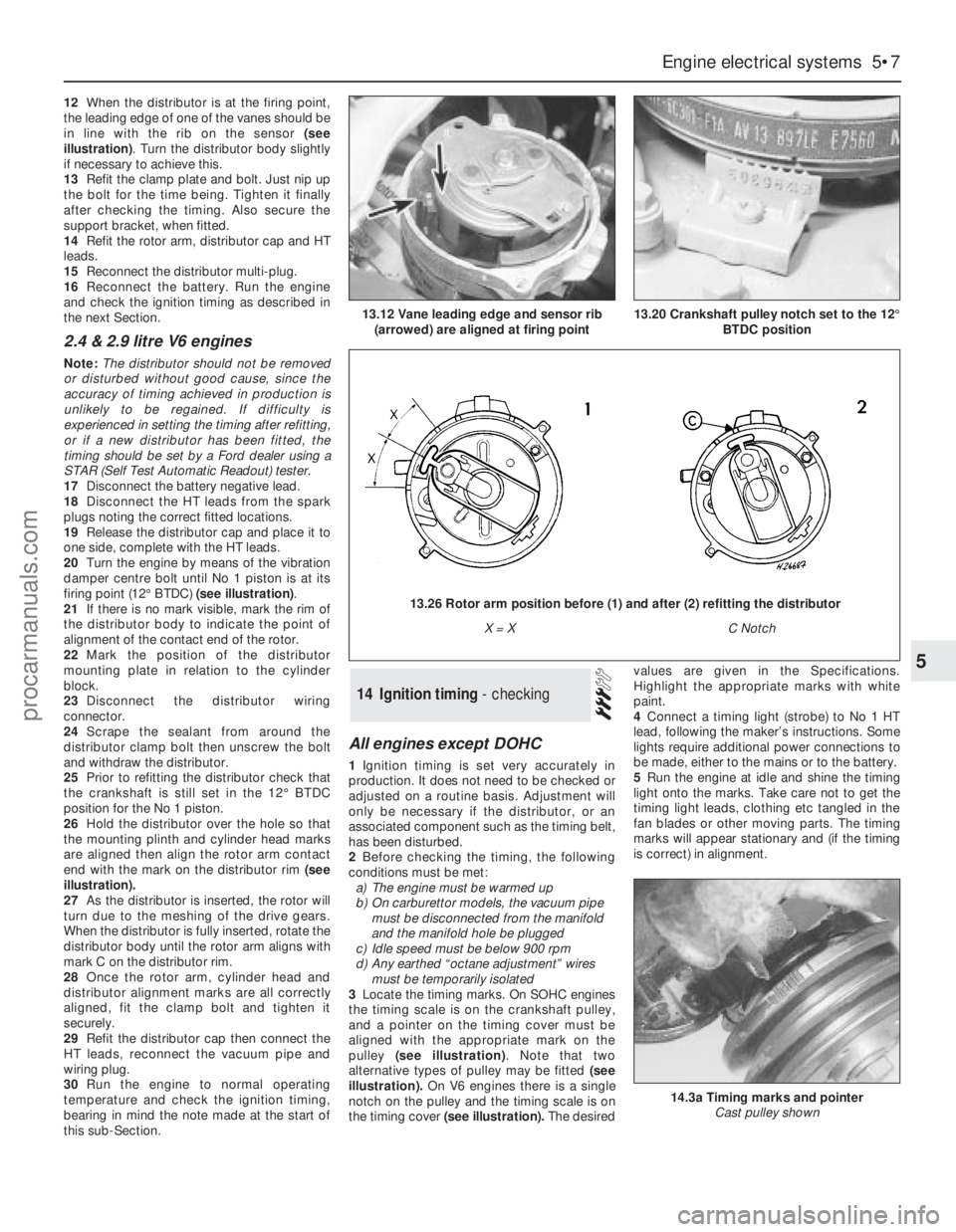
12When the distributor is at the firing point,
the leading edge of one of the vanes should be
in line with the rib on the sensor (see
illustration). Turn the distributor body slightly
if necessary to achieve this.
13Refit the clamp plate and bolt. Just nip up
the bolt for the time being. Tighten it finally
after checking the timing. Also secure the
support bracket, when fitted.
14Refit the rotor arm, distributor cap and HT
leads.
15Reconnect the distributor multi-plug.
16Reconnect the battery. Run the engine
and check the ignition timing as described in
the next Section.
2.4 & 2.9 litre V6 engines
Note: The distributor should not be removed
or disturbed without good cause, since the
accuracy of timing achieved in production is
unlikely to be regained. If difficulty is
experienced in setting the timing after refitting,
or if a new distributor has been fitted, the
timing should be set by a Ford dealer using a
STAR (Self Test Automatic Readout) tester.
17Disconnect the battery negative lead.
18Disconnect the HT leads from the spark
plugs noting the correct fitted locations.
19Release the distributor cap and place it to
one side, complete with the HT leads.
20Turn the engine by means of the vibration
damper centre bolt until No 1 piston is at its
firing point (12°BTDC) (see illustration).
21If there is no mark visible, mark the rim of
the distributor body to indicate the point of
alignment of the contact end of the rotor.
22Mark the position of the distributor
mounting plate in relation to the cylinder
block.
23Disconnect the distributor wiring
connector.
24Scrape the sealant from around the
distributor clamp bolt then unscrew the bolt
and withdraw the distributor.
25Prior to refitting the distributor check that
the crankshaft is still set in the 12°BTDC
position for the No 1 piston.
26Hold the distributor over the hole so that
the mounting plinth and cylinder head marks
are aligned then align the rotor arm contact
end with the mark on the distributor rim (see
illustration).
27As the distributor is inserted, the rotor will
turn due to the meshing of the drive gears.
When the distributor is fully inserted, rotate the
distributor body until the rotor arm aligns with
mark C on the distributor rim.
28Once the rotor arm, cylinder head and
distributor alignment marks are all correctly
aligned, fit the clamp bolt and tighten it
securely.
29Refit the distributor cap then connect the
HT leads, reconnect the vacuum pipe and
wiring plug.
30Run the engine to normal operating
temperature and check the ignition timing,
bearing in mind the note made at the start of
this sub-Section.
All engines except DOHC
1Ignition timing is set very accurately in
production. It does not need to be checked or
adjusted on a routine basis. Adjustment will
only be necessary if the distributor, or an
associated component such as the timing belt,
has been disturbed.
2Before checking the timing, the following
conditions must be met:
a)The engine must be warmed up
b)On carburettor models, the vacuum pipe
must be disconnected from the manifold
and the manifold hole be plugged
c)Idle speed must be below 900 rpm
d)Any earthed “octane adjustment” wires
must be temporarily isolated
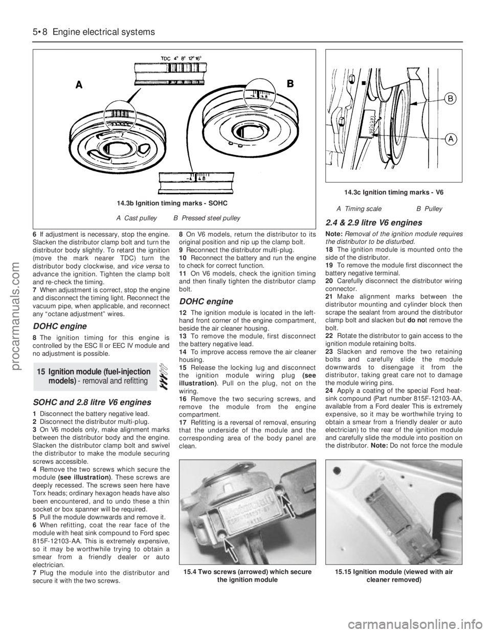
3Locate the timing marks. On SOHC engines
the timing scale is on the crankshaft pulley,
and a pointer on the timing cover must be
aligned with the appropriate mark on the
pulley (see illustration). Note that two
alternative types of pulley may be fitted (see
illustration).On V6 engines there is a single
notch on the pulley and the timing scale is on
the timing cover (see illustration).The desiredvalues are given in the Specifications.
Highlight the appropriate marks with white
paint.
4Connect a timing light (strobe) to No 1 HT
lead, following the maker’s instructions. Some
lights require additional power connections to
be made, either to the mains or to the battery.
5Run the engine at idle and shine the timing
light onto the marks. Take care not to get the
timing light leads, clothing etc tangled in the
fan blades or other moving parts. The timing
marks will appear stationary and (if the timing
is correct) in alignment.
14Ignition timing - checking
Engine electrical systems 5•7
5
13.12 Vane leading edge and sensor rib
(arrowed) are aligned at firing point13.20 Crankshaft pulley notch set to the 12°
BTDC position
14.3a Timing marks and pointer
Cast pulley shown
13.26 Rotor arm position before (1) and after (2) refitting the distributor
X = XC Notch
procarmanuals.com
Page 125 of 255
6If adjustment is necessary, stop the engine.
Slacken the distributor clamp bolt and turn the
distributor body slightly. To retard the ignition
(move the mark nearer TDC) turn the
distributor body clockwise, and vice versato
advance the ignition. Tighten the clamp bolt
and re-check the timing.
7When adjustment is correct, stop the engine
and disconnect the timing light. Reconnect the
vacuum pipe, when applicable, and reconnect
any “octane adjustment” wires.
DOHC engine
8The ignition timing for this engine is
controlled by the ESC II or EEC IV module and
no adjustment is possible.
SOHC and 2.8 litre V6 engines
1Disconnect the battery negative lead.
2Disconnect the distributor multi-plug.
3On V6 models only, make alignment marks
between the distributor body and the engine.
Slacken the distributor clamp bolt and swivel
the distributor to make the module securing
screws accessible.
4Remove the two screws which secure the
module (see illustration). These screws are
deeply recessed. The screws seen here have
Torx heads; ordinary hexagon heads have also
been encountered, and to undo these a thin
socket or box spanner will be required.
5Pull the module downwards and remove it.
6When refitting, coat the rear face of the
module with heat sink compound to Ford spec
815F-12103-AA. This is extremely expensive,
so it may be worthwhile trying to obtain a
smear from a friendly dealer or auto
electrician.
7Plug the module into the distributor and
secure it with the two screws.8On V6 models, return the distributor to its
original position and nip up the clamp bolt.
9Reconnect the distributor multi-plug.
10Reconnect the battery and run the engine
to check for correct function.
11On V6 models, check the ignition timing
and then finally tighten the distributor clamp
bolt.
DOHC engine
12The ignition module is located in the left-
hand front corner of the engine compartment,
beside the air cleaner housing.
13To remove the module, first disconnect
the battery negative lead.
14To improve access remove the air cleaner
housing.
15Release the locking lug and disconnect
the ignition module wiring plug (see
illustration). Pull on the plug, not on the
wiring.
16Remove the two securing screws, and
remove the module from the engine
compartment.
17Refitting is a reversal of removal, ensuring
that the underside of the module and the
corresponding area of the body panel are
clean.
2.4 & 2.9 litre V6 engines
Note: Removal of the ignition module requires
the distributor to be disturbed.
18The ignition module is mounted onto the
side of the distributor.
19To remove the module first disconnect the
battery negative terminal.
20Carefully disconnect the distributor wiring
connector.
21Make alignment marks between the
distributor mounting and cylinder block then
scrape the sealant from around the distributor
clamp bolt and slacken but do not remove the
bolt.
22Rotate the distributor to gain access to the
ignition module retaining bolts.
23Slacken and remove the two retaining
bolts and carefully slide the module
downwards to disengage it from the
distributor, taking great care not to damage
the module wiring pins.
24Apply a coating of the special Ford heat-
sink compound (Part number 815F-12103-AA,
available from a Ford dealer This is extremely
expensive, so it may be worthwhile trying to
obtain a smear from a friendly dealer or auto
electrician) to the rear of the ignition module
and carefully slide the module into position on
the distributor. Note: Do not force the module
15Ignition module (fuel-injection
models) - removal and refitting
5•8Engine electrical systems
15.4 Two screws (arrowed) which secure
the ignition module15.15 Ignition module (viewed with air
cleaner removed)
14.3c Ignition timing marks - V6
A Timing scaleB Pulley14.3b Ignition timing marks - SOHC
A Cast pulleyB Pressed steel pulley
procarmanuals.com
Page 126 of 255
into position or the wiring pins will be
damaged.
25Refit the module retaining bolts and
tighten them securely.
26Rotate the distributor until the marks made
on removal are aligned then securely tighten
the clamp bolt.
27Reconnect the distributor wiring
connector and the battery negative terminal.
28Run the engine to normal operating
temperature and check the ignition timing.
All engines except DOHC fuel-
injection
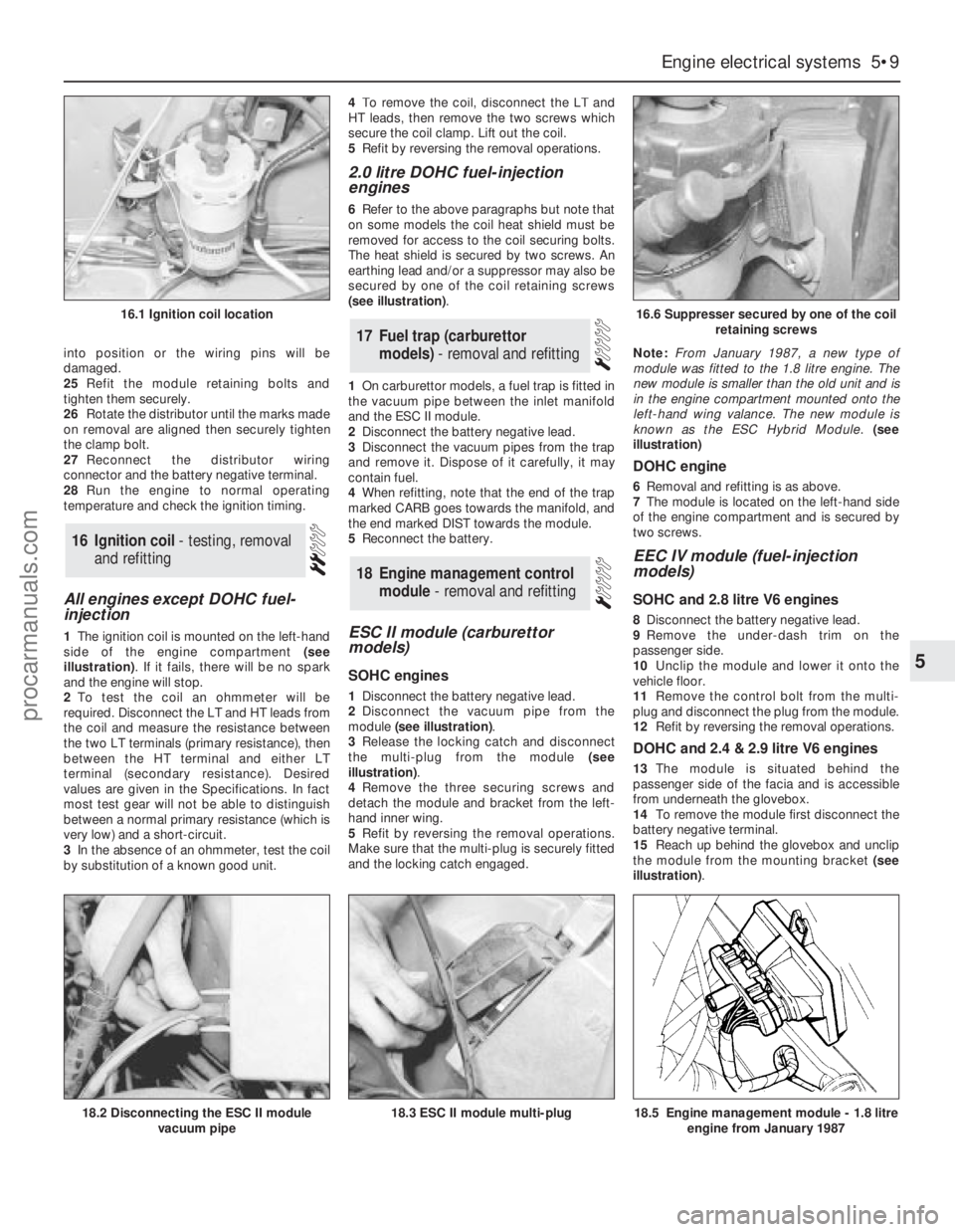
1The ignition coil is mounted on the left-hand
side of the engine compartment (see
illustration). If it fails, there will be no spark
and the engine will stop.
2To test the coil an ohmmeter will be
required. Disconnect the LT and HT leads from
the coil and measure the resistance between
the two LT terminals (primary resistance), then
between the HT terminal and either LT
terminal (secondary resistance). Desired
values are given in the Specifications. In fact
most test gear will not be able to distinguish
between a normal primary resistance (which is
very low) and a short-circuit.
3In the absence of an ohmmeter, test the coil
by substitution of a known good unit.4To remove the coil, disconnect the LT and
HT leads, then remove the two screws which
secure the coil clamp. Lift out the coil.
5Refit by reversing the removal operations.
2.0 litre DOHC fuel-injection
engines
6Refer to the above paragraphs but note that
on some models the coil heat shield must be
removed for access to the coil securing bolts.
The heat shield is secured by two screws. An
earthing lead and/or a suppressor may also be
secured by one of the coil retaining screws
(see illustration).
1On carburettor models, a fuel trap is fitted in
the vacuum pipe between the inlet manifold
and the ESC II module.
2Disconnect the battery negative lead.
3Disconnect the vacuum pipes from the trap
and remove it. Dispose of it carefully, it may
contain fuel.
4When refitting, note that the end of the trap
marked CARB goes towards the manifold, and
the end marked DIST towards the module.
5Reconnect the battery.
ESC II module (carburettor
models)
SOHC engines
1Disconnect the battery negative lead.
2Disconnect the vacuum pipe from the
module (see illustration).
3Release the locking catch and disconnect
the multi-plug from the module (see
illustration).
4Remove the three securing screws and
detach the module and bracket from the left-
hand inner wing.
5Refit by reversing the removal operations.
Make sure that the multi-plug is securely fitted
and the locking catch engaged.Note: From January 1987, a new type of
module was fitted to the 1.8 litre engine. The
new module is smaller than the old unit and is
in the engine compartment mounted onto the
left-hand wing valance. The new module is
known as the ESC Hybrid Module.(see
illustration)
DOHC engine
6Removal and refitting is as above.
7The module is located on the left-hand side
of the engine compartment and is secured by
two screws.
EEC IV module (fuel-injection
models)
SOHC and 2.8 litre V6 engines
8Disconnect the battery negative lead.
9Remove the under-dash trim on the
passenger side.
10Unclip the module and lower it onto the
vehicle floor.
11Remove the control bolt from the multi-
plug and disconnect the plug from the module.
12Refit by reversing the removal operations.
DOHC and 2.4 & 2.9 litre V6 engines
13The module is situated behind the
passenger side of the facia and is accessible
from underneath the glovebox.
14To remove the module first disconnect the
battery negative terminal.
15Reach up behind the glovebox and unclip
the module from the mounting bracket (see
illustration).
18Engine management control
module - removal and refitting
17Fuel trap (carburettor
models) - removal and refitting
16Ignition coil - testing, removal
and refitting
Engine electrical systems 5•9
5
16.1 Ignition coil location16.6 Suppresser secured by one of the coil
retaining screws
18.2 Disconnecting the ESC II module
vacuum pipe18.5 Engine management module - 1.8 litre
engine from January 198718.3 ESC II module multi-plug
procarmanuals.com
Page 127 of 255
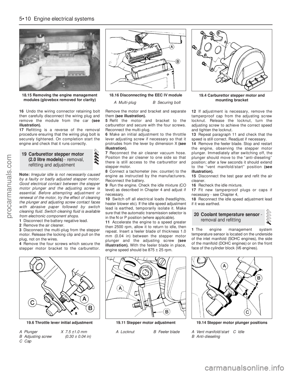
16Undo the wiring connector retaining bolt
then carefully disconnect the wiring plug and
remove the module from the car (see
illustration).
17Refitting is a reverse of the removal
procedure ensuring that the wiring plug bolt is
securely tightened. On completion start the
engine and check that it runs correctly.
Note: Irregular idle is not necessarily caused
by a faulty or badly adjusted stepper motor.
Good electrical contact between the stepper
motor plunger and the adjusting screw is
essential. Before attempting adjustment or
renewal of the motor, try the effect of cleaning
the plunger and adjusting screw contact faces
with abrasive paper followed by switch
cleaning fluid. Switch cleaning fluid is available
from electronic component shops.
1Disconnect the battery negative lead.
2Remove the air cleaner.
3Disconnect the multi-plug from the stepper
motor. Release the locking clip and pull on the
plug, not on the wires.
4Remove the four screws which secure the
stepper motor bracket to the carburettor.Remove the motor and bracket and separate
them (see illustration).
5Refit the motor and bracket to the
carburettor and secure with the four screws.
Reconnect the multi-plug.
6Make an initial adjustment to the throttle
lever adjusting screw if necessary so that it
protrudes from the lever by dimension X (see
illustration).
7Reconnect the air cleaner vacuum hose.
Position the air cleaner to one side so that
there is still access to the carburettor and
stepper motor.
8Connect a tachometer (rev. counter) to the
engine as instructed by the manufacturers.
Reconnect the battery.
9Run the engine. Check the idle mixture (CO
level) as described in Chapter 4 and adjust if
necessary.
10Switch off all electrical loads (headlights,
heater blower etc). If the idle speed adjustment
lead is earthed, temporarily isolate it. Make
sure that the automatic transmission selector is
in the N or P position (where applicable).
11Accelerate the engine to a speed greater
then 2500 rpm, allow it to return to idle, then
repeat. Insert a feeler blade of thickness 1.0
mm (0.04 in) between the stepper motor
plunger and the adjusting screw(see
illustration).With the feeler blade in place,
engine speed should be 875 ±25 rpm. 12If adjustment is necessary, remove the
tamperproof cap from the adjusting screw
locknut. Release the locknut, turn the
adjusting screw to achieve the correct speed
and tighten the locknut.
13Repeat paragraph 11 and check that the
speed is still correct. Readjust if necessary.
14Remove the feeler blade. Stop and restart
the engine, observing the stepper motor
plunger. Immediately after switching off, the
plunger should move to the “anti-dieseling”
position; after a few seconds it should extend
to the “vent manifold/start” position (see
illustration).
15Disconnect the test gear and refit the air
cleaner.
16Recheck the idle mixture.
17Fit new tamperproof plugs or caps if
necessary - see Chapter 4,
18Reconnect the idle speed adjustment lead
if it was earthed.
1The engine management system
temperature sensor is located on the underside
of the inlet manifold (SOHC engines), the side
of the manifold (DOHC engines) or on the front
face of the cylinder block (V6 engines).
20Coolant temperature sensor -
removal and refitting
19Carburettor stepper motor
(2.0 litre models) - removal,
refitting and adjustment
5•10Engine electrical systems
18.16 Disconnecting the EEC IV module
A Multi-plugB Securing bolt
19.6 Throttle lever initial adjustment
A Plunger
B Adjusting screw
C CapX 7.5 ±1.0 mm
(0.30 ±0.04 in)
19.11 Stepper motor adjustment
A LocknutB Feeler blade
19.14 Stepper motor plunger positions
A Vent manifold/start
B Anti-dieselingC Idle
19.4 Carburettor stepper motor and
mounting bracket18.15 Removing the engine management
modules (glovebox removed for clarity)
procarmanuals.com
Page 128 of 255
2Disconnect the battery negative lead.
3Drain the cooling system (Chapter 3). Save
the coolant if it is fit for re-use.
4Disconnect the multi-plug from the sensor.
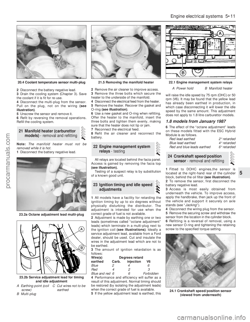
Pull on the plug, not on the wiring (see
illustration).
5Unscrew the sensor and remove it.
6Refit by reversing the removal operations.
Refill the cooling system.
Note: The manifold heater must not be
removed while it is hot.
1Disconnect the battery negative lead. 2Remove the air cleaner to improve access.
3Remove the three bolts which secure the
heater to the underside of the manifold.
4Disconnect the electrical feed from the heater.
5Remove the heater. Recover the gasket and
O-ring (see illustration).
6Use a new gasket and O-ring when refitting.
Offer the heater to the manifold, insert the
three bolts and tighten them evenly, making
sure that the heater does not tip or jam.
7Reconnect the electrical feed.
8Refit the air cleaner and reconnect the
battery.
All relays are located behind the facia panel.
Access is gained by removing the facia top
(see illustration).
Testing of a suspect relay is by substitution
of a known good unit.
1All models have a facility for retarding the
ignition timing by up to six degrees without
physically disturbing the distributor. The
adjustment is intended for use when the
correct grade of fuel is not available.
2Adjustment is made by earthing one or two
leads (sometimes called “octane adjustment”
leads) which terminate in a multi-plug next to
the ignition coil (see illustrations). Ideally a
service adjustment lead, available from a Ford
dealer, should be used. Cut and insulate the
wires in the adjustment lead which are not to
be earthed.
3The amount of ignition retardation is as
follows:
Wire(s) Degrees retard
earthed Carb. injection V6
Blue 2 4 6
Red 4 2 3
Blue and red 6 6 Forbidden
4Performance and efficiency will suffer as a
result of this adjustment. Normal timing should
be restored (by isolating the adjustment leads)
when the correct grade of fuel is available.
5If the yellow adjustment lead is earthed, thiswill raise the idle speed by 75 rpm (OHC) or 50
rpm (V6). It may be found that the yellow lead
has already been earthed in production, in
which case disconnecting it will lower the idle
speed by the same amount. This adjustment
does not apply to 1.8 litre carburettor models.
1.8 models from January 1987
6The effect of the “octane adjustment” leads
on these models fitted with the ESC Hybrid
Module is as follows.
Red lead earthed2°retarded
Blue lead earthed4°retarded
Red and blue leads earthed6°retarded
1Fitted to DOHC engines,the sensor is
located at the right-hand rear of the cylinder
block, behind the oil filter (see illustration).
2To remove the sensor, first disconnect the
battery negative lead.
3Access is most easily obtained from
underneath the vehicle. To improve access,
apply the handbrake, then jack up the front of
the vehicle and support it securely on axle
stands (see “Jacking”).
4Disconnect the wiring plug from the sensor.
5Remove the securing screw and withdraw the
sensor from the location in the cylinder block.
6Refitting is a reversal of removal, using a
new sensor O-ring and tightening the retaining
screw to the specified torque setting.
24Crankshaft speed/position
sensor - removal and refitting
23Ignition timing and idle speed
adjustments
22Engine management system
relays - testing
21Manifold heater (carburettor
models) - removal and refitting
Engine electrical systems 5•11
5
20.4 Coolant temperature sensor multi-plug21.5 Removing the manifold heater22.1 Engine management system relays
A Power holdB Manifold heater
23.2a Octane adjustment lead multi-plug
23.2b Service adjustment lead for timing
and idle adjustment
A Earthing point (coil
screw)
B Multi-plugC Cut wires not to be
earthed
24.1 Crankshaft speed/position sensor
(viewed from underneath)
procarmanuals.com
Page 129 of 255
1The sensor is located in the upper section of
the inlet manifold (DOHC fuel-injection
engines) or the side of the plenum chamber
(V6 engines).
2To remove the sensor, first disconnect the
battery negative lead.
3Disconnect the sensor wiring plug by pulling
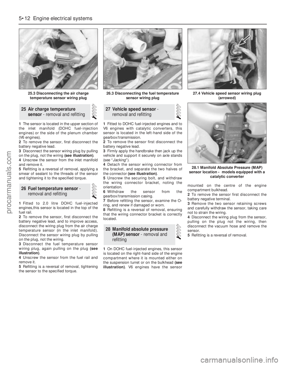
on the plug, not the wiring (see illustration).
4Unscrew the sensor from the inlet manifold
and remove it.
5Refitting is a reversal of removal, applying a
smear of sealant to the threads of the sensor
and tightening it to the specified torque.
1Fitted to 2.0 litre DOHC fuel-injected
engines,this sensor is located in the top of the
fuel rail.
2To remove the sensor, first disconnect the
battery negative lead, and to improve access,
disconnect the wiring plug from the air charge
temperature sensor (in the inlet manifold).
Disconnect the sensor wiring plug by pulling
on the plug, not the wiring.
3Disconnect the fuel temperature sensor
wiring plug, again pulling on the plug (see
illustration).
4Unscrew the sensor from the fuel rail and
remove it.
5Refitting is a reversal of removal, tightening
the sensor to the specified torque.1Fitted to DOHC fuel-injected engines and to
V6 engines with catalytic converters, this
sensor is located in the left-hand side of the
gearbox/transmission.
2To remove the sensor first disconnect the
battery negative lead.
3Firmly apply the handbrake then jack up the
vehicle and support it securely on axle stands
(see “Jacking”).
4Detach the sensor wiring connector from
the bracket, and separate the two halves of
the connector (see illustration).
5Unscrew the securing bolt, and withdraw
the wiring connector bracket, noting the
orientation.
6Withdraw the sensor from the
gearbox/transmission casing.
7Before refitting the sensor, examine the O-
ring, and renew if damaged or worn.
8Refitting is a reversal of removal, ensuring
that the wiring connector bracket is correctly
located.
1On DOHC fuel-injected engines, this sensor
is located on the right-hand side of the engine
compartment where it is mounted either on
the suspension turret or on the bulkhead (see
illustration). V6 engines have the sensormounted on the centre of the engine
compartment bulkhead.
2To remove the sensor first disconnect the
battery negative terminal.
3Remove the two sensor retaining screws
and carefully withdraw the sensor, taking care
not to strain the wiring.
4Disconnect the wiring plug from the sensor,
pulling on the plug not the wiring, then
disconnect the vacuum hose and remove the
sensor.
5Refitting is a reversal of removal.
28Manifold absolute pressure
(MAP) sensor - removal and
refitting
27Vehicle speed sensor -
removal and refitting
26Fuel temperature sensor -
removal and refitting
25Air charge temperature
sensor - removal and refitting
5•12Engine electrical systems
25.3 Disconnecting the air charge
temperature sensor wiring plug
28.1 Manifold Absolute Pressure (MAP)
sensor location - models equipped with a
catalytic converter
26.3 Disconnecting the fuel temperature
sensor wiring plug27.4 Vehicle speed sensor wiring plug
(arrowed)
procarmanuals.com
Page 141 of 255
3Press the multi-plug locking lever,
disconnect the multi-plug and unhook it from
the module. Remove the module.
4Refit by reversing the removal operations.
Make sure that the multi-plug is properly
engaged before refitting the module.
Front
1Ensure that the handbrake is applied. Raise
and support the front of the vehicle.
2From under the bonnet disconnect the
wheel sensor wiring multi-plug. Unclip the
wiring, working towards the sensor.
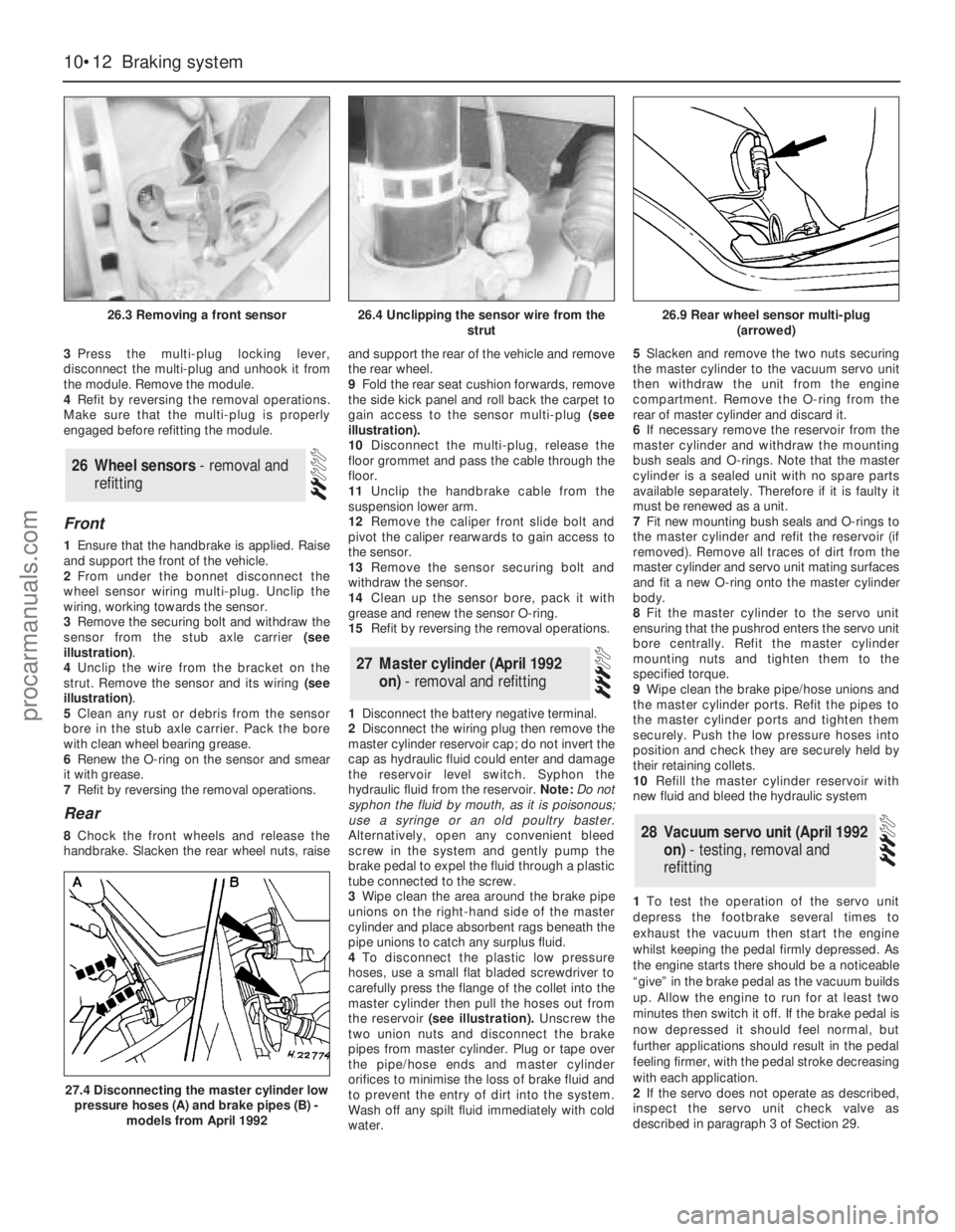
3Remove the securing bolt and withdraw the
sensor from the stub axle carrier (see
illustration).
4Unclip the wire from the bracket on the
strut. Remove the sensor and its wiring (see
illustration).
5Clean any rust or debris from the sensor
bore in the stub axle carrier. Pack the bore
with clean wheel bearing grease.
6Renew the O-ring on the sensor and smear
it with grease.
7Refit by reversing the removal operations.
Rear
8Chock the front wheels and release the
handbrake. Slacken the rear wheel nuts, raiseand support the rear of the vehicle and remove
the rear wheel.
9Fold the rear seat cushion forwards, remove
the side kick panel and roll back the carpet to
gain access to the sensor multi-plug (see
illustration).
10Disconnect the multi-plug, release the
floor grommet and pass the cable through the
floor.
11Unclip the handbrake cable from the
suspension lower arm.
12Remove the caliper front slide bolt and
pivot the caliper rearwards to gain access to
the sensor.
13Remove the sensor securing bolt and
withdraw the sensor.
14Clean up the sensor bore, pack it with
grease and renew the sensor O-ring.
15Refit by reversing the removal operations.
1Disconnect the battery negative terminal.
2Disconnect the wiring plug then remove the
master cylinder reservoir cap; do not invert the
cap as hydraulic fluid could enter and damage
the reservoir level switch. Syphon the
hydraulic fluid from the reservoir. Note: Do not
syphon the fluid by mouth, as it is poisonous;
use a syringe or an old poultry baster.
Alternatively, open any convenient bleed
screw in the system and gently pump the
brake pedal to expel the fluid through a plastic
tube connected to the screw.
3Wipe clean the area around the brake pipe
unions on the right-hand side of the master
cylinder and place absorbent rags beneath the
pipe unions to catch any surplus fluid.
4To disconnect the plastic low pressure
hoses, use a small flat bladed screwdriver to
carefully press the flange of the collet into the
master cylinder then pull the hoses out from
the reservoir(see illustration).Unscrew the
two union nuts and disconnect the brake
pipes from master cylinder. Plug or tape over
the pipe/hose ends and master cylinder
orifices to minimise the loss of brake fluid and
to prevent the entry of dirt into the system.
Wash off any spilt fluid immediately with cold
water.5Slacken and remove the two nuts securing
the master cylinder to the vacuum servo unit
then withdraw the unit from the engine
compartment. Remove the O-ring from the
rear of master cylinder and discard it.
6If necessary remove the reservoir from the
master cylinder and withdraw the mounting
bush seals and O-rings. Note that the master
cylinder is a sealed unit with no spare parts
available separately. Therefore if it is faulty it
must be renewed as a unit.
7Fit new mounting bush seals and O-rings to
the master cylinder and refit the reservoir (if
removed). Remove all traces of dirt from the
master cylinder and servo unit mating surfaces
and fit a new O-ring onto the master cylinder
body.
8Fit the master cylinder to the servo unit
ensuring that the pushrod enters the servo unit
bore centrally. Refit the master cylinder
mounting nuts and tighten them to the
specified torque.
9Wipe clean the brake pipe/hose unions and
the master cylinder ports. Refit the pipes to
the master cylinder ports and tighten them
securely. Push the low pressure hoses into
position and check they are securely held by
their retaining collets.
10Refill the master cylinder reservoir with
new fluid and bleed the hydraulic system
1To test the operation of the servo unit
depress the footbrake several times to
exhaust the vacuum then start the engine
whilst keeping the pedal firmly depressed. As
the engine starts there should be a noticeable
“give” in the brake pedal as the vacuum builds
up. Allow the engine to run for at least two
minutes then switch it off. If the brake pedal is
now depressed it should feel normal, but
further applications should result in the pedal
feeling firmer, with the pedal stroke decreasing
with each application.
2If the servo does not operate as described,
inspect the servo unit check valve as
describedin paragraph 3 of Section 29.28Vacuum servo unit (April 1992
on) - testing, removal and
refitting
27Master cylinder (April 1992
on) - removal and refitting
26Wheel sensors - removal and
refitting
10•12Braking system
26.3 Removing a front sensor
27.4 Disconnecting the master cylinder low
pressure hoses (A) and brake pipes (B) -
models from April 1992
26.4 Unclipping the sensor wire from the
strut26.9 Rear wheel sensor multi-plug
(arrowed)
procarmanuals.com
Page 142 of 255
3If the servo unit still fails to operate
satisfactorily the fault lies within the unit itself.
Repairs to the unit are not possible.
4Remove the master cylinder (Section 27).
5Disconnect the vacuum hose from the servo
unit taking care not to displace the rubber
sealing grommet. Disconnect the wiring plug
from the Pedal Travel Sensor (PTS) which is
situated on the front of the servo.
6Working from inside the vehicle, remove the
servo pushrod retaining clip from the brake
pedal. If necessary, to improve access to the
brake pedal remove the right-hand lower facia
panel .
7Slacken and remove the four nuts securing
the servo unit to the bulkhead, then return to
the engine compartment and remove the
servo unit from the vehicle. Remove the
gasket from the rear of the unit and discard it.
8Note that the vacuum servo unit is a sealed
assembly with no spare parts available
separately. Therefore if it is faulty it must be
renewed as a unit. Inspect the vacuum servo
vacuum hose sealing grommet for damage or
deterioration and renew if necessary.
9Remove all traces of dirt from the servo unit
and bulkhead mating surfaces and fit a new
gasket onto the rear of the servo.
10Manoeuvre the servo unit into position,
ensuring that the servo unit pushrod is
correctly located with the hole in the pedal.
Refit the servo unit retaining nuts and tighten
them to the specified torque setting. Secure
the pushrod in position with the retaining clip
11Carefully refit the vacuum hose to the servo
unit taking great care not to damage or displace
the sealing grommet. Reconnect the wiring
connector to the Pedal Travel Sensor (PTS).
12Refit the master cylinder as described
above. On completion start the engine and
check the operation of the servo unit.
1Disconnect the vacuum hose from the servo
unit taking care not to displace the rubber
sealing grommet.
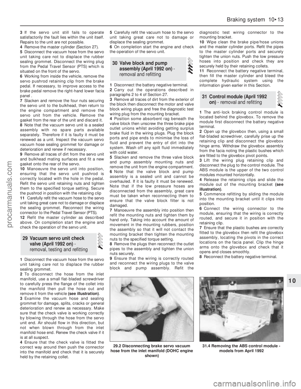
2To disconnect the hose from the inlet
manifold, use a small flat-bladed screwdriver
to carefully press the flange of the collet into
the manifold then pull the hose out and
remove it from the vehicle (see illustration).
3Examine the vacuum hose and sealing
grommet for damage, splits, cracks or general
deterioration and renew as necessary. Make
sure that the check valve is working correctly
by blowing through the hose from the servo
unit end. Air should flow in this direction, but
not when blown through from the inlet
manifold hose end. Renew the check valve if it
is at all suspect.
4Ensure that the check valve is fitted the
correct way around then push the connector
into the manifold and check that it is securely
held by the retaining collet.5Carefully refit the vacuum hose to the servo
unit taking great care not to damage or
displace the sealing grommet.
6On completion start the engine and check
the operation of the servo unit.
1Disconnect the battery negative terminal.
2Carry out the operations described in
paragraphs 2 to 4 of Section 27.
3Remove all traces of dirt from the exterior of
the block then disconnect the motor and valve
block wiring plugs and free the diagnostic test
wiring plug from the mounting bracket.
4Position some absorbent rag beneath the
valve block then unscrew the three brake pipe
outlet unions whilst avoiding getting surplus
brake fluid in the wiring plugs. Plug the block
ports and pipe ends to minimise the loss of
fluid and prevent the entry of dirt into the
system. Wash off any spilt fluid immediately
with cold water.
5Slacken and remove the three valve block
and pump assembly mounting nuts and
remove the unit from the engine compartment.
6Note that the valve block and pump
assembly is a sealed unit and cannot be
overhauled. If it is faulty it must be renewed.
Note that if the low pressure hoses are
disconnected from the assembly, great care
must be taken when reconnecting them to
ensure that the valve block filter is not
damaged.
7Manoeuvre the assembly into position then
refit the mounting nuts and tighten them by
hand only. Taking into account the amount of
movement in the mounting rubbers, position
the assembly so that it will not contact the
mounting bracket then tighten the mounting
nuts to the specified torque setting.
8Remove the plugs then reconnect the outlet
pipes to the assembly and tighten the union
nuts securely.
9Ensure that the wiring is correctly routed
and reconnect the wiring plugs to the valve
block and pump assembly. Refit thediagnostic test wiring connector to the
mounting bracket.
10Wipe clean the brake pipe/hose unions
and the master cylinder ports. Refit the pipes
to the master cylinder ports and securely
tighten the union nuts. Push the low pressure
hoses into position and check they are
securely held by their retaining collets.
11Reconnect the battery negative terminal,
then fill the master cylinder and bleed the
complete hydraulic system using the
information given earlier in this Section.
1The anti-lock braking control module is
located behind the glovebox. To remove the
module first disconnect the battery negative
terminal.
2Open up the glovebox then, using a small
flat-bladed screwdriver, carefully prise up the
retaining clip and disconnect the glovebox
hinge arms. Withdraw the glovebox assembly
from the facia noting the plastic bushes which
are fitted to the glovebox pivot points.
3Lift the wiring plug retaining clip and
disconnect the plug to the control module. The
ABS module is the upper of the two control
modules mounted horizontally.
4Release the retaining clips and slide the
module out of the mounting bracket (see
illustration).
5Commence refitting by sliding the module
into the mounting bracket until it clips into
position.
6Connect the wiring connector to the
module, ensuring that the wiring is correctly
routed, and secure it in position with the
retaining clip.
7Ensure that the plastic bushes are correctly
fitted to the glovebox then refit the glovebox
assembly, locating the pivots in the correct
locations on the facia panel. Clip the hinge
arms onto the glovebox and check that it
opens and closes smoothly.
8Reconnect the battery negative terminal.
31Control module (April 1992
on) - removal and refitting
30Valve block and pump
assembly (April 1992 on) -
removal and refitting
29 Vacuum servo unit check
valve (April 1992 on) -
removal, testing and refitting
Braking system 10•13
10
29.2 Disconnecting brake servo vacuum
hose from the inlet manifold (DOHC engine
shown)31.4 Removing the ABS control module -
models from April 1992
procarmanuals.com