1985 FORD GRANADA ECU
[x] Cancel search: ECUPage 128 of 255
2Disconnect the battery negative lead.
3Drain the cooling system (Chapter 3). Save
the coolant if it is fit for re-use.
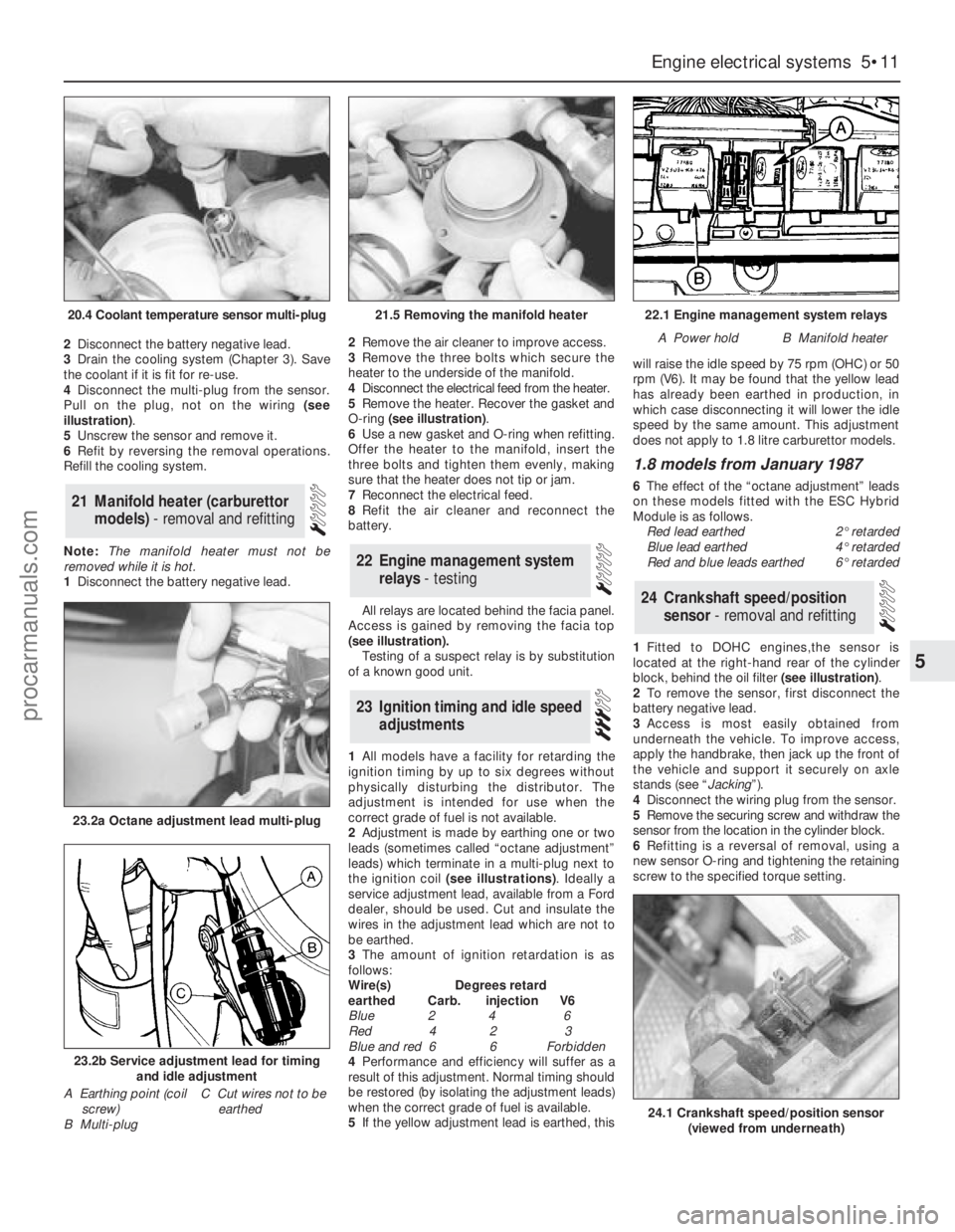
4Disconnect the multi-plug from the sensor.
Pull on the plug, not on the wiring (see
illustration).
5Unscrew the sensor and remove it.
6Refit by reversing the removal operations.
Refill the cooling system.
Note: The manifold heater must not be
removed while it is hot.
1Disconnect the battery negative lead. 2Remove the air cleaner to improve access.
3Remove the three bolts which secure the
heater to the underside of the manifold.
4Disconnect the electrical feed from the heater.
5Remove the heater. Recover the gasket and
O-ring (see illustration).
6Use a new gasket and O-ring when refitting.
Offer the heater to the manifold, insert the
three bolts and tighten them evenly, making
sure that the heater does not tip or jam.
7Reconnect the electrical feed.
8Refit the air cleaner and reconnect the
battery.
All relays are located behind the facia panel.
Access is gained by removing the facia top
(see illustration).
Testing of a suspect relay is by substitution
of a known good unit.
1All models have a facility for retarding the
ignition timing by up to six degrees without
physically disturbing the distributor. The
adjustment is intended for use when the
correct grade of fuel is not available.
2Adjustment is made by earthing one or two
leads (sometimes called “octane adjustment”
leads) which terminate in a multi-plug next to
the ignition coil (see illustrations). Ideally a
service adjustment lead, available from a Ford
dealer, should be used. Cut and insulate the
wires in the adjustment lead which are not to
be earthed.
3The amount of ignition retardation is as
follows:
Wire(s) Degrees retard
earthed Carb. injection V6
Blue 2 4 6
Red 4 2 3
Blue and red 6 6 Forbidden
4Performance and efficiency will suffer as a
result of this adjustment. Normal timing should
be restored (by isolating the adjustment leads)
when the correct grade of fuel is available.
5If the yellow adjustment lead is earthed, thiswill raise the idle speed by 75 rpm (OHC) or 50
rpm (V6). It may be found that the yellow lead
has already been earthed in production, in
which case disconnecting it will lower the idle
speed by the same amount. This adjustment
does not apply to 1.8 litre carburettor models.
1.8 models from January 1987
6The effect of the “octane adjustment” leads
on these models fitted with the ESC Hybrid
Module is as follows.
Red lead earthed2°retarded
Blue lead earthed4°retarded
Red and blue leads earthed6°retarded
1Fitted to DOHC engines,the sensor is
located at the right-hand rear of the cylinder
block, behind the oil filter (see illustration).
2To remove the sensor, first disconnect the
battery negative lead.
3Access is most easily obtained from
underneath the vehicle. To improve access,
apply the handbrake, then jack up the front of
the vehicle and support it securely on axle
stands (see “Jacking”).
4Disconnect the wiring plug from the sensor.
5Remove the securing screw and withdraw the
sensor from the location in the cylinder block.
6Refitting is a reversal of removal, using a
new sensor O-ring and tightening the retaining
screw to the specified torque setting.
24Crankshaft speed/position
sensor - removal and refitting
23Ignition timing and idle speed
adjustments
22Engine management system
relays - testing
21Manifold heater (carburettor
models) - removal and refitting
Engine electrical systems 5•11
5
20.4 Coolant temperature sensor multi-plug21.5 Removing the manifold heater22.1 Engine management system relays
A Power holdB Manifold heater
23.2a Octane adjustment lead multi-plug
23.2b Service adjustment lead for timing
and idle adjustment
A Earthing point (coil
screw)
B Multi-plugC Cut wires not to be
earthed
24.1 Crankshaft speed/position sensor
(viewed from underneath)
procarmanuals.com
Page 129 of 255
1The sensor is located in the upper section of
the inlet manifold (DOHC fuel-injection
engines) or the side of the plenum chamber
(V6 engines).
2To remove the sensor, first disconnect the
battery negative lead.
3Disconnect the sensor wiring plug by pulling
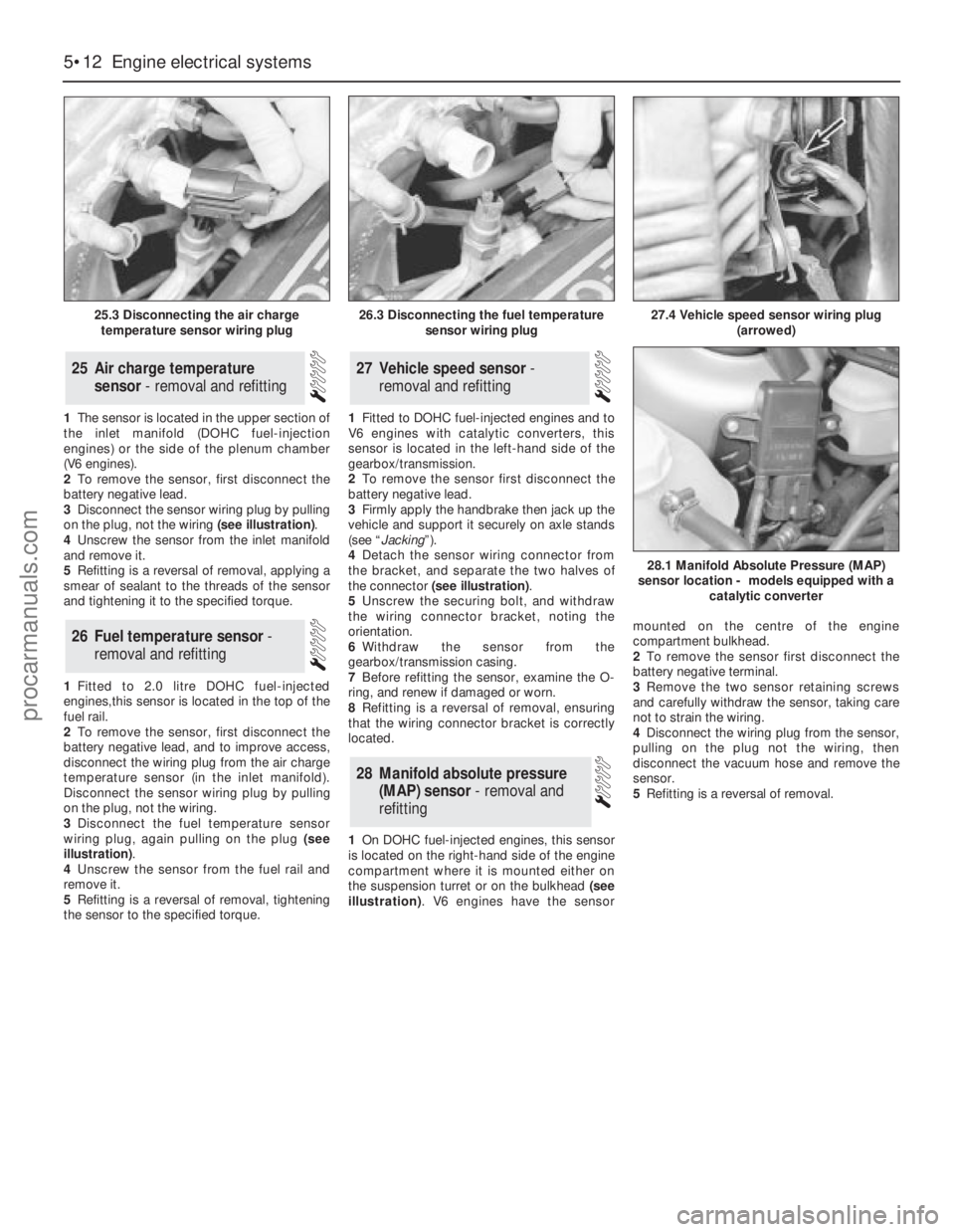
on the plug, not the wiring (see illustration).
4Unscrew the sensor from the inlet manifold
and remove it.
5Refitting is a reversal of removal, applying a
smear of sealant to the threads of the sensor
and tightening it to the specified torque.
1Fitted to 2.0 litre DOHC fuel-injected
engines,this sensor is located in the top of the
fuel rail.
2To remove the sensor, first disconnect the
battery negative lead, and to improve access,
disconnect the wiring plug from the air charge
temperature sensor (in the inlet manifold).
Disconnect the sensor wiring plug by pulling
on the plug, not the wiring.
3Disconnect the fuel temperature sensor
wiring plug, again pulling on the plug (see
illustration).
4Unscrew the sensor from the fuel rail and
remove it.
5Refitting is a reversal of removal, tightening
the sensor to the specified torque.1Fitted to DOHC fuel-injected engines and to
V6 engines with catalytic converters, this
sensor is located in the left-hand side of the
gearbox/transmission.
2To remove the sensor first disconnect the
battery negative lead.
3Firmly apply the handbrake then jack up the
vehicle and support it securely on axle stands
(see “Jacking”).
4Detach the sensor wiring connector from
the bracket, and separate the two halves of
the connector (see illustration).
5Unscrew the securing bolt, and withdraw
the wiring connector bracket, noting the
orientation.
6Withdraw the sensor from the
gearbox/transmission casing.
7Before refitting the sensor, examine the O-
ring, and renew if damaged or worn.
8Refitting is a reversal of removal, ensuring
that the wiring connector bracket is correctly
located.
1On DOHC fuel-injected engines, this sensor
is located on the right-hand side of the engine
compartment where it is mounted either on
the suspension turret or on the bulkhead (see
illustration). V6 engines have the sensormounted on the centre of the engine
compartment bulkhead.
2To remove the sensor first disconnect the
battery negative terminal.
3Remove the two sensor retaining screws
and carefully withdraw the sensor, taking care
not to strain the wiring.
4Disconnect the wiring plug from the sensor,
pulling on the plug not the wiring, then
disconnect the vacuum hose and remove the
sensor.
5Refitting is a reversal of removal.
28Manifold absolute pressure
(MAP) sensor - removal and
refitting
27Vehicle speed sensor -
removal and refitting
26Fuel temperature sensor -
removal and refitting
25Air charge temperature
sensor - removal and refitting
5•12Engine electrical systems
25.3 Disconnecting the air charge
temperature sensor wiring plug
28.1 Manifold Absolute Pressure (MAP)
sensor location - models equipped with a
catalytic converter
26.3 Disconnecting the fuel temperature
sensor wiring plug27.4 Vehicle speed sensor wiring plug
(arrowed)
procarmanuals.com
Page 133 of 255
and bracket off the disc and tie them up out of
the way. Do not allow the caliper to hang on
the flexible hose.
3Remove the spring clip which secures the
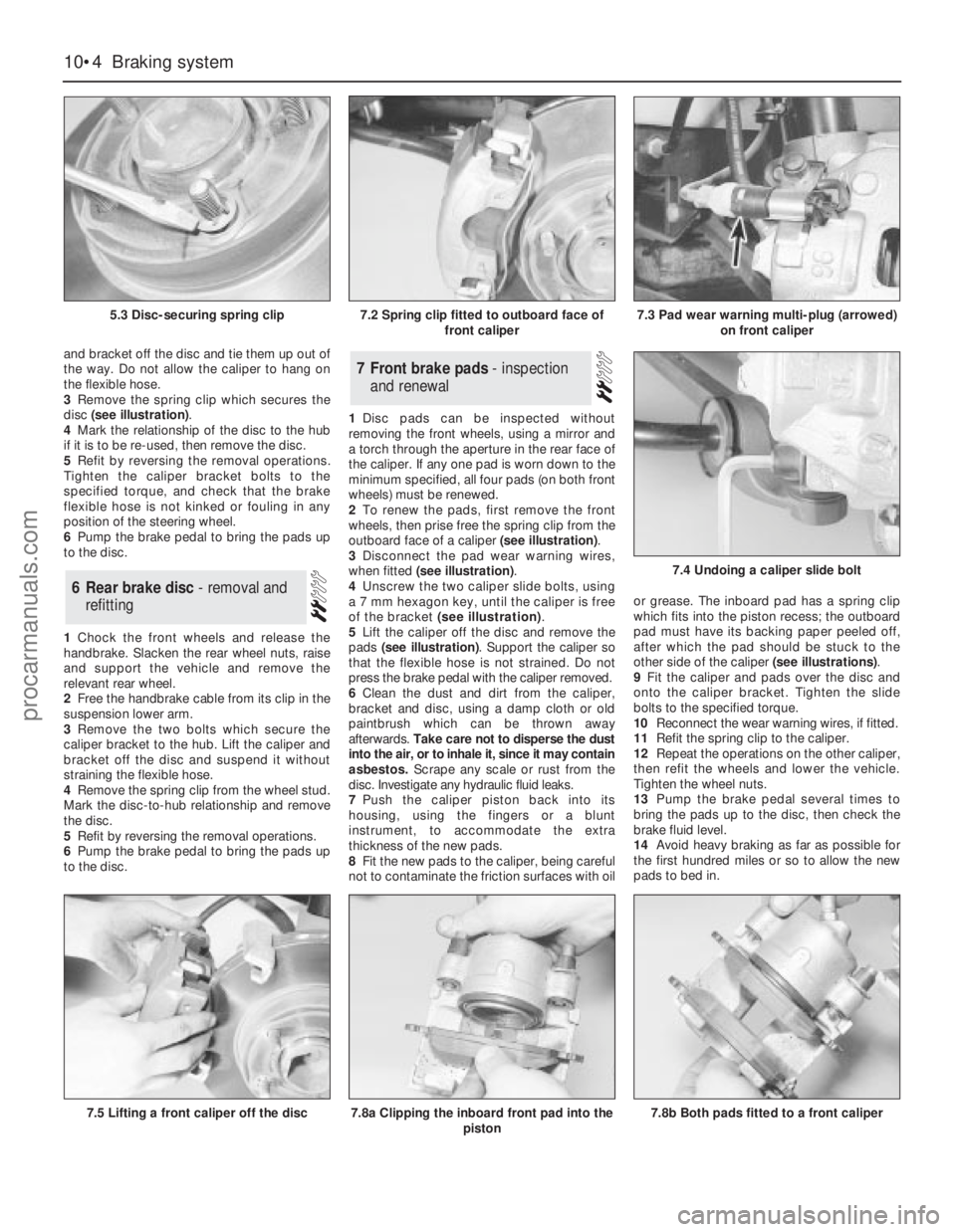
disc (see illustration).
4Mark the relationship of the disc to the hub
if it is to be re-used, then remove the disc.
5Refit by reversing the removal operations.
Tighten the caliper bracket bolts to the
specified torque, and check that the brake
flexible hose is not kinked or fouling in any
position of the steering wheel.
6Pump the brake pedal to bring the pads up
to the disc.
1Chock the front wheels and release the
handbrake. Slacken the rear wheel nuts, raise
and support the vehicle and remove the
relevant rear wheel.
2Free the handbrake cable from its clip in the
suspension lower arm.
3Remove the two bolts which secure the
caliper bracket to the hub. Lift the caliper and
bracket off the disc and suspend it without
straining the flexible hose.
4Remove the spring clip from the wheel stud.
Mark the disc-to-hub relationship and remove
the disc.
5Refit by reversing the removal operations.
6Pump the brake pedal to bring the pads up
to the disc.1Disc pads can be inspected without
removing the front wheels, using a mirror and
a torch through the aperture in the rear face of
the caliper. If any one pad is worn down to the
minimum specified, all four pads (on both front
wheels) must be renewed.
2To renew the pads, first remove the front
wheels, then prise free the spring clip from the
outboard face of a caliper (see illustration).
3Disconnect the pad wear warning wires,
when fitted (see illustration).
4Unscrew the two caliper slide bolts, using
a 7 mm hexagon key, until the caliper is free
of the bracket (see illustration).
5Lift the caliper off the disc and remove the
pads (see illustration). Support the caliper so
that the flexible hose is not strained. Do not
press the brake pedal with the caliper removed.
6Clean the dust and dirt from the caliper,
bracket and disc, using a damp cloth or old
paintbrush which can be thrown away
afterwards. Take care not to disperse the dust
into the air, or to inhale it, since it may contain
asbestos. Scrape any scale or rust from the
disc. Investigate any hydraulic fluid leaks.
7Push the caliper piston back into its
housing, using the fingers or a blunt
instrument, to accommodate the extra
thickness of the new pads.
8Fit the new pads to the caliper, being careful
not to contaminate the friction surfaces with oilor grease. The inboard pad has a spring clip
which fits into the piston recess; the outboard
pad must have its backing paper peeled off,
after which the pad should be stuck to the
other side of the caliper (see illustrations).
9Fit the caliper and pads over the disc and
onto the caliper bracket. Tighten the slide
bolts to the specified torque.
10Reconnect the wear warning wires, if fitted.
11Refit the spring clip to the caliper.
12Repeat the operations on the other caliper,
then refit the wheels and lower the vehicle.
Tighten the wheel nuts.
13Pump the brake pedal several times to
bring the pads up to the disc, then check the
brake fluid level.
14Avoid heavy braking as far as possible for
the first hundred miles or so to allow the new
pads to bed in.7Front brake pads - inspection
and renewal
6Rear brake disc - removal and
refitting
10•4Braking system
5.3 Disc-securing spring clip
7.5 Lifting a front caliper off the disc7.8a Clipping the inboard front pad into the
piston
7.4 Undoing a caliper slide bolt
7.8b Both pads fitted to a front caliper
7.2 Spring clip fitted to outboard face of
front caliper7.3 Pad wear warning multi-plug (arrowed)
on front caliper
procarmanuals.com
Page 134 of 255
1It is necessary to remove the rear wheels in
order to inspect the rear pads. The pads can
be viewed through the top of the caliper after
removing the spring clip. If any one pad is
worn down to the minimum specified, all four
pads (on both rear wheels) must be renewed.
2Free the handbrake cable from its clip on
the suspension lower arm. Release the
handbrake.
3Remove the caliper slide bolt nearest the
front, counter-holding the slide pin with
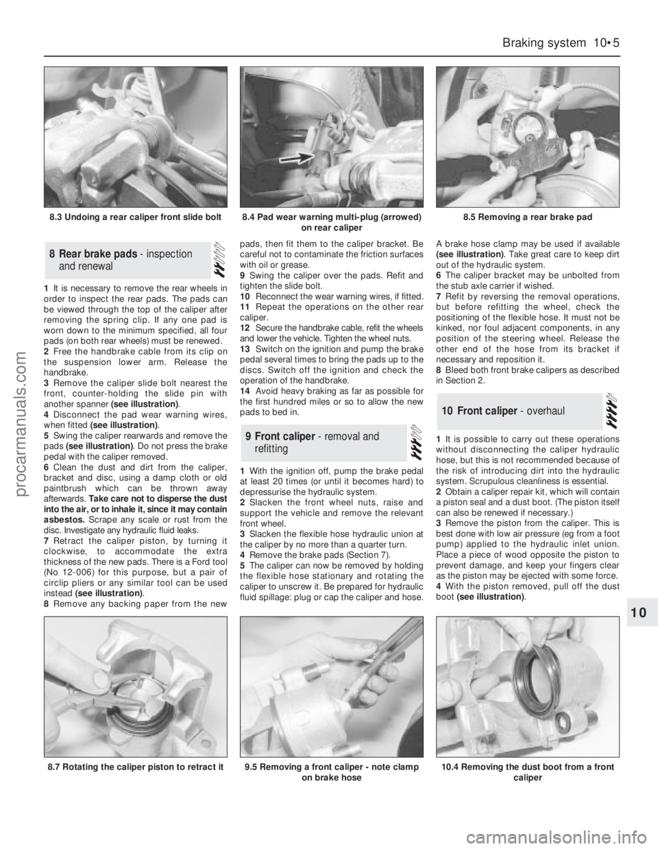
another spanner (see illustration).
4Disconnect the pad wear warning wires,
when fitted (see illustration).
5Swing the caliper rearwards and remove the
pads (see illustration). Do not press the brake
pedal with the caliper removed.
6Clean the dust and dirt from the caliper,
bracket and disc, using a damp cloth or old
paintbrush which can be thrown away
afterwards. Take care not to disperse the dust
into the air, or to inhale it, since it may contain
asbestos. Scrape any scale or rust from the
disc. Investigate any hydraulic fluid leaks.
7Retract the caliper piston, by turning it
clockwise, to accommodate the extra
thickness of the new pads. There is a Ford tool
(No 12-006) for this purpose, but a pair of
circlip pliers or any similar tool can be used
instead (see illustration).
8Remove any backing paper from the newpads, then fit them to the caliper bracket. Be
careful not to contaminate the friction surfaces
with oil or grease.
9Swing the caliper over the pads. Refit and
tighten the slide bolt.
10Reconnect the wear warning wires, if fitted.
11Repeat the operations on the other rear
caliper.
12Secure the handbrake cable, refit the wheels
and lower the vehicle. Tighten the wheel nuts.
13Switch on the ignition and pump the brake
pedal several times to bring the pads up to the
discs. Switch off the ignition and check the
operation of the handbrake.
14Avoid heavy braking as far as possible for
the first hundred miles or so to allow the new
pads to bed in.
1With the ignition off, pump the brake pedal
at least 20 times (or until it becomes hard) to
depressurise the hydraulic system.
2Slacken the front wheel nuts, raise and
support the vehicle and remove the relevant
front wheel.
3Slacken the flexible hose hydraulic union at
the caliper by no more than a quarter turn.
4Remove the brake pads (Section 7).
5The caliper can now be removed by holding
the flexible hose stationary and rotating the
caliper to unscrew it. Be prepared for hydraulic
fluid spillage: plug or cap the caliper and hose.A brake hose clamp may be used if available
(see illustration). Take great care to keep dirt
out of the hydraulic system.
6The caliper bracket may be unbolted from
the stub axle carrier if wished.
7Refit by reversing the removal operations,
but before refitting the wheel, check the
positioning of the flexible hose. It must not be
kinked, nor foul adjacent components, in any
position of the steering wheel. Release the
other end of the hose from its bracket if
necessary and reposition it.
8Bleed both front brake calipers as described
in Section 2.
1It is possible to carry out these operations
without disconnecting the caliper hydraulic
hose, but this is not recommended because of
the risk of introducing dirt into the hydraulic
system. Scrupulous cleanliness is essential.
2Obtain a caliper repair kit, which will contain
a piston seal and a dust boot. (The piston itself
can also be renewed if necessary.)
3Remove the piston from the caliper. This is
best done with low air pressure (eg from a foot
pump) applied to the hydraulic inlet union.
Place a piece of wood opposite the piston to
prevent damage, and keep your fingers clear
as the piston may be ejected with some force.
4With the piston removed, pull off the dust
boot (see illustration).
10Front caliper - overhaul
9Front caliper - removal and
refitting
8Rear brake pads - inspection
and renewal
Braking system 10•5
10
8.3 Undoing a rear caliper front slide bolt8.4 Pad wear warning multi-plug (arrowed)
on rear caliper8.5 Removing a rear brake pad
8.7 Rotating the caliper piston to retract it9.5 Removing a front caliper - note clamp
on brake hose10.4 Removing the dust boot from a front
caliper
procarmanuals.com
Page 136 of 255
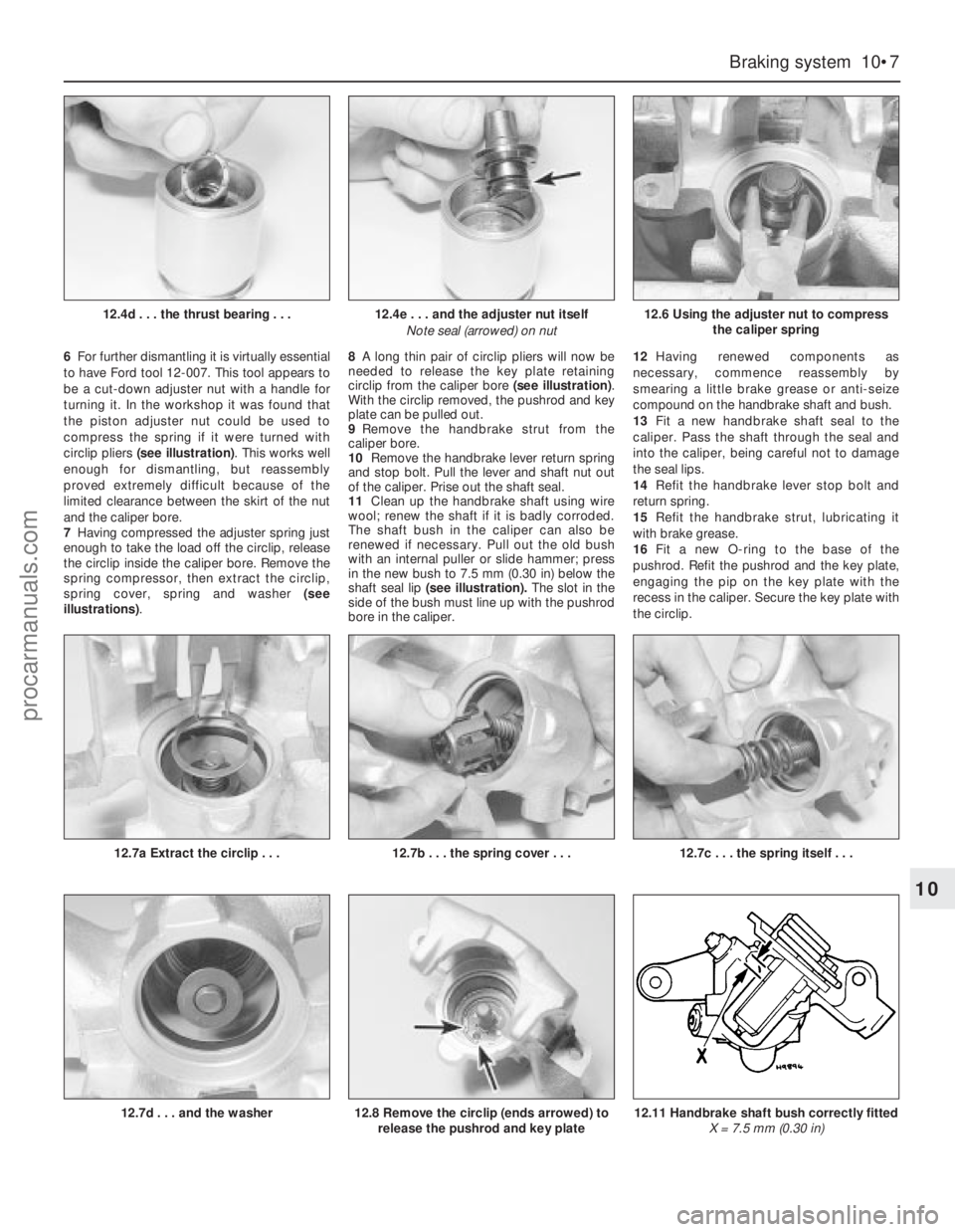
6For further dismantling it is virtually essential
to have Ford tool 12-007. This tool appears to
be a cut-down adjuster nut with a handle for
turning it. In the workshop it was found that
the piston adjuster nut could be used to
compress the spring if it were turned with
circlip pliers (see illustration). This works well
enough for dismantling, but reassembly
proved extremely difficult because of the
limited clearance between the skirt of the nut
and the caliper bore.
7Having compressed the adjuster spring just
enough to take the load off the circlip, release
the circlip inside the caliper bore. Remove the
spring compressor, then extract the circlip,
spring cover, spring and washer (see
illustrations). 8A long thin pair of circlip pliers will now be
needed to release the key plate retaining
circlip from the caliper bore (see illustration).
With the circlip removed, the pushrod and key
plate can be pulled out.
9Remove the handbrake strut from the
caliper bore.
10Remove the handbrake lever return spring
and stop bolt. Pull the lever and shaft nut out
of the caliper. Prise out the shaft seal.
11Clean up the handbrake shaft using wire
wool; renew the shaft if it is badly corroded.
The shaft bush in the caliper can also be
renewed if necessary. Pull out the old bush
with an internal puller or slide hammer; press
in the new bush to 7.5 mm (0.30 in) below the
shaft seal lip(seeillustration).The slot in the
side of the bush must line up with the pushrod
bore in the caliper.12Having renewed components as
necessary, commence reassembly by
smearing a little brake grease or anti-seize
compound on the handbrake shaft and bush.
13Fit a new handbrake shaft seal to the
caliper. Pass the shaft through the seal and
into the caliper, being careful not to damage
the seal lips.
14Refit the handbrake lever stop bolt and
return spring.
15Refit the handbrake strut, lubricating it
with brake grease.
16Fit a new O-ring to the base of the
pushrod. Refit the pushrod and the key plate,
engaging the pip on the key plate with the
recess in the caliper. Secure the key plate with
the circlip.
Braking system 10•7
10
12.4e . . . and the adjuster nut itself
Note seal (arrowed) on nut
12.7c . . . the spring itself . . .
12.6 Using the adjuster nut to compress
the caliper spring
12.7a Extract the circlip . . .12.7b . . . the spring cover . . .
12.7d . . . and the washer12.11 Handbrake shaft bush correctly fitted
X = 7.5 mm (0.30 in)12.8 Remove the circlip (ends arrowed) to
release the pushrod and key plate
12.4d . . . the thrust bearing . . .
procarmanuals.com
Page 137 of 255
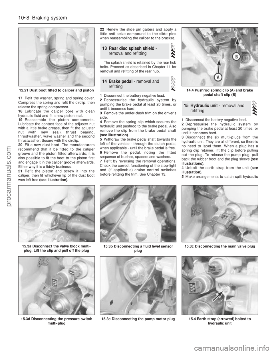
17Refit the washer, spring and spring cover.
Compress the spring and refit the circlip, then
release the spring compressor.
18Lubricate the caliper bore with clean
hydraulic fluid and fit a new piston seal.
19Reassemble the piston components.
Lubricate the contact face of the adjuster nut
with a little brake grease, then fit the adjuster
nut (with new seal), thrust bearing,
thrustwasher, wave washer and the second
thrustwasher. Secure with the circlip.
20Fit a new dust boot. The manufacturers
recommend that it be fitted to the caliper
groove and the piston fitted afterwards; it is
also possible to fit the boot to the piston first
and engage it in the caliper groove afterwards.
Either way it is a fiddly business.
21Refit the piston and screw it into the
caliper, then fit whichever lip of the dust boot
was left free (see illustration).22Renew the slide pin gaiters and apply a
little anti-seize compound to the slide pins
when reassembling the caliper to the bracket.
The splash shield is retained by the rear hub
bolts. Proceed as described in Chapter 11 for
removal and refitting of the rear hub.
1Disconnect the battery negative lead.
2Depressurise the hydraulic system by
pumping the brake pedal at least 20 times, or
until it becomes hard.
3Remove the under-dash trim on the driver’s
side.
4Remove the spring clip which secures the
hydraulic unit pushrod to the brake pedal. Also
remove the clip from the brake pedal shaft
(see illustration).
5Withdraw the brake pedal shaft towards the
left of the vehicle - through the clutch pedal,
when applicable - until the brake pedal is free.
6Remove the pedal, noting the fitted
sequence of bushes, spacers and washers.
7Refit by reversing the removal operations.
Check the correct functioning of the stop-light
and (if applicable) cruise control switches
before refitting the trim. See Chapter 13.1Disconnect the battery negative lead.
2Depressurise the hydraulic system by
pumping the brake pedal at least 20 times, or
until it becomes hard.
3Disconnect the six multi-plugs from the
hydraulic unit. They are all different, so there is
no need to label them. When a plug has a
spring clip retainer, lift the clip before pulling
out the plug. To release the pump plug, pull
back the rubber boot and the plug sleeve (see
illustrations).
4Unbolt the earth strap from the unit (see
illustration).
5Make arrangements to catch spilt hydraulic
15Hydraulic unit - removal and
refitting
14Brake pedal - removal and
refitting
13Rear disc splash shield -
removal and refitting
10•8Braking system
12.21 Dust boot fitted to caliper and piston
15.3d Disconnecting the pressure switch
multi-plug15.3e Disconnecting the pump motor plug15.4 Earth strap (arrowed) bolted to
hydraulic unit
14.4 Pushrod spring clip (A) and brake
pedal shaft clip (B)
15.3a Disconnect the valve block multi-
plug. Lift the clip and pull off the plug15.3b Disconnecting a fluid level sensor
plug15.3c Disconnecting the main valve plug
procarmanuals.com
Page 138 of 255
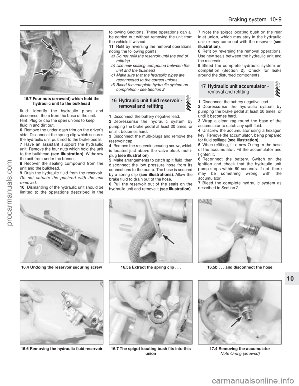
fluid. Identify the hydraulic pipes and
disconnect them from the base of the unit.
Hint: Plug or cap the open unions to keep
fluid in and dirt out.
6Remove the under-dash trim on the driver’s
side. Disconnect the spring clip which secures
the hydraulic unit pushrod to the brake pedal.
7Have an assistant support the hydraulic
unit. Remove the four nuts which hold the unit
to the bulkhead (see illustration). Withdraw
the unit from under the bonnet.
8Recover the sealing compound from the
unit and the bulkhead.
9Drain the hydraulic fluid from the reservoir.
Do not actuate the pushrod with the unit
removed.
10Dismantling of the hydraulic unit should be
limited to the operations described in thefollowing Sections. These operations can all
be carried out without removing the unit from
the vehicle if wished.
11Refit by reversing the removal operations,
noting the following points:
a)Do not refill the reservoir until the end of
refitting
b)Use new sealing compound between the
unit and the bulkhead
c)Make sure that the hydraulic pipes are
reconnected to the correct unions
d)Bleed the complete hydraulic system on
completion - see Section 2
1Disconnect the battery negative lead.
2Depressurise the hydraulic system by
pumping the brake pedal at least 20 times, or
until it becomes hard.
3Disconnect the multi-plugs and remove the
reservoir cap.
4Remove the reservoir securing screw, which
is located just above the valve block multi-
plug (see illustration).
5Make arrangements to catch spilt fluid, then
disconnect the low pressure hose from its
connections to the pump. The hose is secured
by a spring clip (see illustrations). Allow the
brake fluid to drain out of the hose.
6Pull the reservoir out of the seals on the
hydraulic unit and remove it (see illustration).7Note the spigot locating bush on the rear
inlet union, which may stay in the hydraulic
unit or may come out with the reservoir (see
illustration).
8Refit by reversing the removal operations.
Use new seals between the hydraulic unit and
the reservoir.
9Bleed the complete hydraulic system on
completion (Section 2). Check for leaks
around the disturbed components.
1Disconnect the battery negative lead.
2Depressurise the hydraulic system by
pumping the brake pedal at least 20 times, or
until it becomes hard.
3Wrap a clean rag round the base of the
accumulator to catch any spilt fluid.
4Unscrew the accumulator using a hexagon
key. Remove the accumulator, being prepared
for fluid spillage (see illustration).
5When refitting, fit a new O-ring to the base
of the accumulator. Fit the accumulator and
tighten it.
6Reconnect the battery. Switch on the
ignition and check that the hydraulic unit
pump stops within 60 seconds. If not, there
may be something wrong with the
accumulator.
7Bleed the complete hydraulic system as
described in Section 2.
17Hydraulic unit accumulator -
removal and refitting
16Hydraulic unit fluid reservoir -
removal and refitting
Braking system 10•9
10
15.7 Four nuts (arrowed) which hold the
hydraulic unit to the bulkhead
16.4 Undoing the reservoir securing screw16.5a Extract the spring clip . . .
16.6 Removing the hydraulic fluid reservoir
16.5b . . . and disconnect the hose
16.7 The spigot locating bush fits into this
union17.4 Removing the accumulator
Note O-ring (arrowed)
procarmanuals.com
Page 139 of 255
1Remove the accumulator (Section 17).
2Disconnect the high pressure hose from the
pump. Be prepared for fluid spillage.
3Disconnect the low pressure hose from the
pump. Allow the fluid to drain out of the
reservoir through the hose.
4Disconnect the multi-plugs from the
pressure switch and the pump motor.
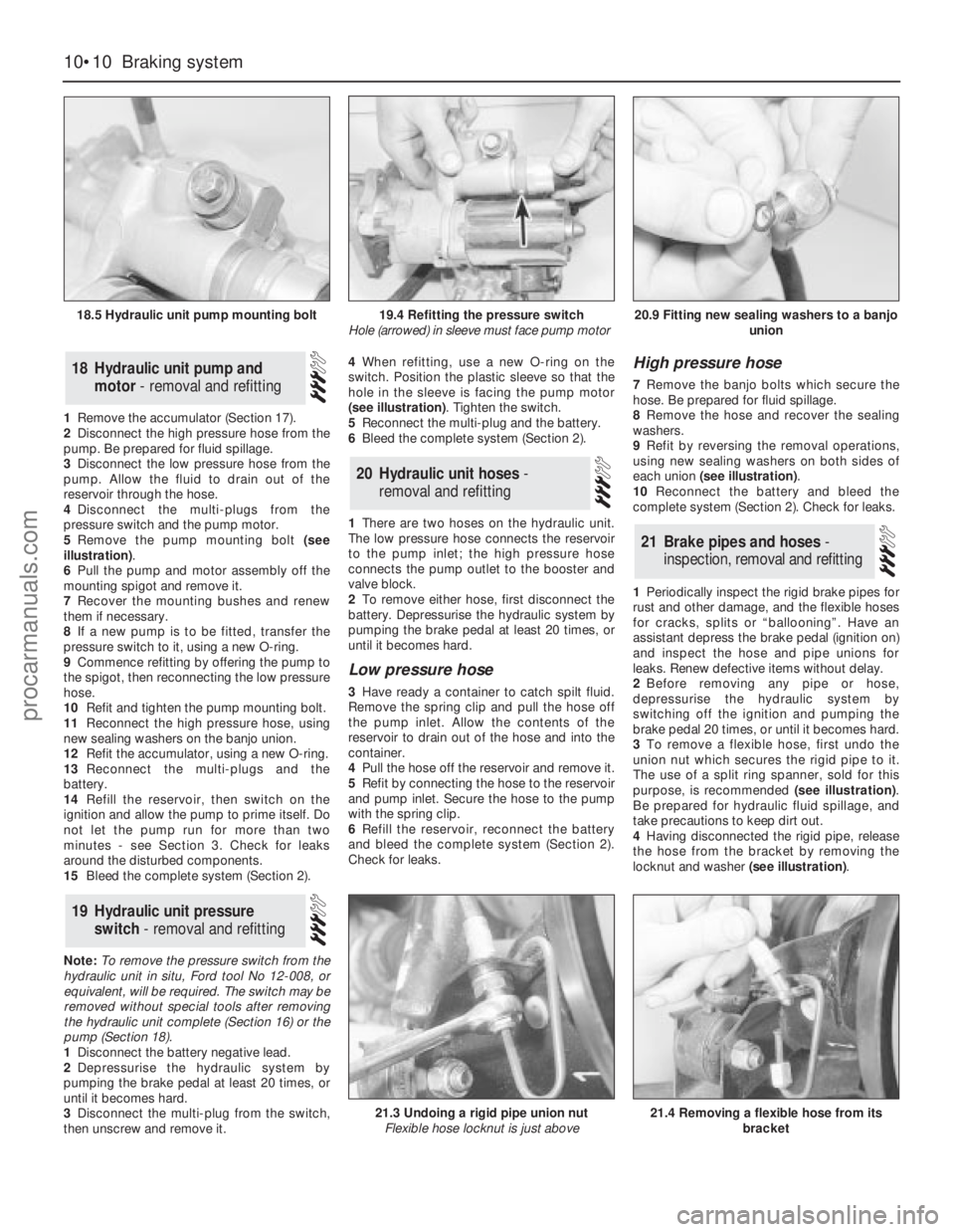
5Remove the pump mounting bolt (see
illustration).
6Pull the pump and motor assembly off the
mounting spigot and remove it.
7Recover the mounting bushes and renew
them if necessary.
8If a new pump is to be fitted, transfer the
pressure switch to it, using a new O-ring.
9Commence refitting by offering the pump to
the spigot, then reconnecting the low pressure
hose.
10Refit and tighten the pump mounting bolt.
11Reconnect the high pressure hose, using
new sealing washers on the banjo union.
12Refit the accumulator, using a new O-ring.
13Reconnect the multi-plugs and the
battery.
14Refill the reservoir, then switch on the
ignition and allow the pump to prime itself. Do
not let the pump run for more than two
minutes - see Section 3. Check for leaks
around the disturbed components.
15Bleed the complete system (Section 2).
Note: To remove the pressure switch from the
hydraulic unit in situ, Ford tool No 12-008, or
equivalent, will be required. The switch may be
removed without special tools after removing
the hydraulic unit complete (Section 16) or the
pump (Section 18).
1Disconnect the battery negative lead.
2Depressurise the hydraulic system by
pumping the brake pedal at least 20 times, or
until it becomes hard.
3Disconnect the multi-plug from the switch,
then unscrew and remove it.4When refitting, use a new O-ring on the
switch. Position the plastic sleeve so that the
hole in the sleeve is facing the pump motor
(see illustration). Tighten the switch.
5Reconnect the multi-plug and the battery.
6Bleed the complete system (Section 2).
1There are two hoses on the hydraulic unit.
The low pressure hose connects the reservoir
to the pump inlet; the high pressure hose
connects the pump outlet to the booster and
valve block.
2To remove either hose, first disconnect the
battery. Depressurise the hydraulic system by
pumping the brake pedal at least 20 times, or
until it becomes hard.
Low pressure hose
3Have ready a container to catch spilt fluid.
Remove the spring clip and pull the hose off
the pump inlet. Allow the contents of the
reservoir to drain out of the hose and into the
container.
4Pull the hose off the reservoir and remove it.
5Refit by connecting the hose to the reservoir
and pump inlet. Secure the hose to the pump
with the spring clip.
6Refill the reservoir, reconnect the battery
and bleed the complete system (Section 2).
Check for leaks.
High pressure hose
7Remove the banjo bolts which secure the
hose. Be prepared for fluid spillage.
8Remove the hose and recover the sealing
washers.
9Refit by reversing the removal operations,
using new sealing washers on both sides of
each union (see illustration).
10Reconnect the battery and bleed the
complete system (Section 2). Check for leaks.
1Periodically inspect the rigid brake pipes for
rust and other damage, and the flexible hoses
for cracks, splits or “ballooning”. Have an
assistant depress the brake pedal (ignition on)
and inspect the hose and pipe unions for
leaks. Renew defective items without delay.
2Before removing any pipe or hose,
depressurise the hydraulic system by
switching off the ignition and pumping the
brake pedal 20 times, or until it becomes hard.
3To remove a flexible hose, first undo the
union nut which secures the rigid pipe to it.
The use of a split ring spanner, sold for this
purpose, is recommended (see illustration).
Be prepared for hydraulic fluid spillage, and
take precautions to keep dirt out.
4Having disconnected the rigid pipe, release
the hose from the bracket by removing the
locknut and washer (see illustration).
21Brake pipes and hoses -
inspection, removal and refitting
20Hydraulic unit hoses -
removal and refitting
19Hydraulic unit pressure
switch - removal and refitting
18Hydraulic unit pump and
motor - removal and refitting
10•10Braking system
18.5 Hydraulic unit pump mounting bolt
21.3 Undoing a rigid pipe union nut
Flexible hose locknut is just above21.4 Removing a flexible hose from its
bracket
19.4 Refitting the pressure switch
Hole (arrowed) in sleeve must face pump motor20.9 Fitting new sealing washers to a banjo
union
procarmanuals.com