1985 FORD GRANADA rims
[x] Cancel search: rimsPage 9 of 255

6Over-inflation will cause rapid wear of the
centre part of the tyre tread, coupled with
reduced adhesion, harsher ride, and the
danger of shock damage occurring in the tyre
casing.
7Regularly check the tyres for damage in the
form of cuts or bulges, especially in the
sidewalls. Remove any nails or stones
embedded in the tread before they penetrate the
tyre to cause deflation. If removal of a nail does
reveal that the tyre has been punctured, refit the
nail so that its point of penetration is marked.
Then immediately change the wheel, and have
the tyre repaired by a tyre dealer. Do not drive on
a tyre in such a condition. If in any doubt as to
the possible consequences of any damage
found, consult your local tyre dealer for advice.
8Periodically remove the wheels, and clean
any dirt or mud from the inside and outside
surfaces. Examine the wheel rims for signs of
rusting, corrosion or other damage. Light alloy
wheels are easily damaged by “kerbing” whilst
parking, and similarly steel wheels may
become dented or buckled. Renewal of the
wheel is very often the only course of remedial
action possible.
9The balance of each wheel and tyre
assembly should be maintained to avoid
excessive wear, not only to the tyres but also
to the steering and suspension components.
Wheel imbalance is normally signified by
vibration through the vehicle’s bodyshell,
although in many cases it is particularly
noticeable through the steering wheel.
Conversely, it should be noted that wear ordamage in suspension or steering
components may cause excessive tyre wear.
Out-of-round or out-of-true tyres, damaged
wheels, and wheel bearing wear also fall into
this category. Balancing will not usually cure
vibration caused by such wear.
10Wheel balancing may be carried out with
the wheel either on or off the vehicle. If
balanced on the vehicle, ensure that the
wheel-to-hub relationship is marked in some
way prior to subsequent wheel removal, so
that it may be refitted in its original position.
11General tyre wear is influenced to a large
degree by driving style - harsh braking and
acceleration, or fast cornering, will all produce
more rapid tyre wear. Interchanging of tyres
may result in more even wear. However, if this
is completely effective, the added expense is
incurred of replacing all four tyres at once,
which may prove financially-restrictive for
many owners.
12Front tyres may wear unevenly as a result
of wheel misalignment. The front wheels
should always be correctly aligned according
to the settings specified by the vehicle
manufacturer.
13Legal restrictions apply to many aspects
of tyre fitting and usage, and in the UK this
information is contained in the Motor Vehicle
Construction and Use Regulations. It is
suggested that a copy of these regulations is
obtained from your local police, if in doubt as
to current legal requirements with regard to
tyre type and condition, minimum tread depth,
etc.Check the operation of all the electrical
equipment, ie. lights, direction indicators,
horn, washers, etc. Refer to the appropriate
Sections of Chapter 13 for details if any of the
circuits are found to be inoperative.
Visually check all accessible wiring
connectors, harnesses and retaining clips for
security, and for signs of chafing or damage.
Rectify any faults found.
Caution: Before carrying out any work on the
vehicle battery, read through the precautions
given in “Safety first!” at the beginning of this
manual.
1The battery fitted as original equipment is
“maintenance-free”, and requires no
maintenance apart from having the case kept
clean, and the terminals clean and tight.
2If a “traditional” type battery is fitted as a
replacement, remove the old cell covers and
check that the plate separators in each cell are
covered by approximately 6 mm (0.25 in) of
electrolyte. If the battery case is translucent,
the cell covers need not be removed to check
the level. Top-up if necessary with distilled or
de-ionized water; do not overfill, and mop up
any spillage at once(see illustration).
6Battery electrolyte level check
5Electrical system check
1•8Weekly checks
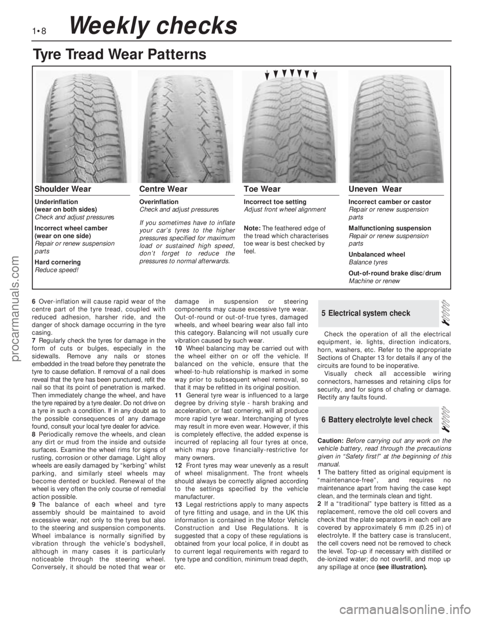
Tyre Tread Wear Patterns
Shoulder Wear
Underinflation
(wear on both sides)
Check and adjust pressures
Incorrect wheel camber
(wear on one side)
Repair or renew suspension
parts
Hard cornering
Reduce speed!
Centre Wear
Overinflation
Check and adjust pressures
If you sometimes have to inflate
your car’s tyres to the higher
pressures specified for maximum
load or sustained high speed,
don’t forget to reduce the
pressures to normal afterwards.
Toe Wear
Incorrect toe setting
Adjust front wheel alignment
Note: The feathered edge of
the tread which characterises
toe wear is best checked by
feel.
Uneven Wear
Incorrect camber or castor
Repair or renew suspension
parts
Malfunctioning suspension
Repair or renew suspension
parts
Unbalanced wheel
Balance tyres
Out-of-round brake disc/drum
Machine or renew
procarmanuals.com
Page 150 of 255

6When refitting, screw the track rod end onto
the track rod as far as the locknut, then back it
off half a turn.
7Insert the ball-pin into the steering arm.
Tighten the balljoint nut to the specified torque
and secure with a new split pin. Nip up the
track rod end locknut, but do not tighten it fully
yet.
8Refit the roadwheel, lower the vehicle and
tighten the wheel nuts to the specified torque.
9Check the toe setting as described in the
following Section. (This may not be strictly
necessary if the same track rod end has been
refitted, but is certainly advisable if any
components have been renewed.)
10Tighten the track rod end locknut when
toe is correct.
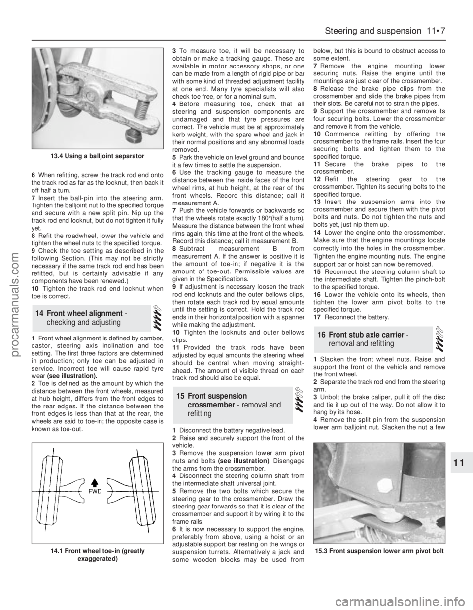
1Front wheel alignment is defined by camber,
castor, steering axis inclination and toe
setting. The first three factors are determined
in production; only toe can be adjusted in
service. Incorrect toe will cause rapid tyre
wear (see illustration).
2Toe is defined as the amount by which the
distance between the front wheels, measured
at hub height, differs from the front edges to
the rear edges. If the distance between the
front edges is less than that at the rear, the
wheels are said to toe-in; the opposite case is
known as toe-out.3To measure toe, it will be necessary to
obtain or make a tracking gauge. These are
available in motor accessory shops, or one
can be made from a length of rigid pipe or bar
with some kind of threaded adjustment facility
at one end. Many tyre specialists will also
check toe free, or for a nominal sum.
4Before measuring toe, check that all
steering and suspension components are
undamaged and that tyre pressures are
correct. The vehicle must be at approximately
kerb weight, with the spare wheel and jack in
their normal positions and any abnormal loads
removed.
5Park the vehicle on level ground and bounce
it a few times to settle the suspension.
6Use the tracking gauge to measure the
distance between the inside faces of the front
wheel rims, at hub height, at the rear of the
front wheels. Record this distance; call it
measurement A.
7Push the vehicle forwards or backwards so
that the wheels rotate exactly 180°(half a turn).
Measure the distance between the front wheel
rims again, this time at the front of the wheels.
Record this distance; call it measurement B.
8Subtract measurement B from
measurement A. If the answer is positive it is
the amount of toe-in; if negative it is the
amount of toe-out. Permissible values are
given in the Specifications.
9If adjustment is necessary loosen the track
rod end locknuts and the outer bellows clips,
then rotate each track rod by equal amounts
until the setting is correct. Hold the track rod
ends in their horizontal position with a spanner
while making the adjustment.
10Tighten the locknuts and outer bellows
clips.
11Provided the track rods have been
adjusted by equal amounts the steering wheel
should be central when moving straight-
ahead. The amount of visible thread on each
track rod should also be equal.
1Disconnect the battery negative lead.
2Raise and securely support the front of the
vehicle.
3Remove the suspension lower arm pivot
nuts and bolts (see illustration). Disengage
the arms from the crossmember.
4Disconnect the steering column shaft from
the intermediate shaft universal joint.
5Remove the two bolts which secure the
steering gear to the crossmember. Draw the
steering gear forwards so that it is clear of the
crossmember and support it by wiring it to the
frame rails.
6It is now necessary to support the engine,
preferably from above, using a hoist or an
adjustable support bar resting on the wings or
suspension turrets. Alternatively a jack and
some wooden blocks may be used frombelow, but this is bound to obstruct access to
some extent.
7Remove the engine mounting lower
securing nuts. Raise the engine until the
mountings are just clear of the crossmember.
8Release the brake pipe clips from the
crossmember and slide the brake pipes from
their slots. Be careful not to strain the pipes.
9Support the crossmember and remove its
four securing bolts. Lower the crossmember
and remove it from the vehicle.
10Commence refitting by offering the
crossmember to the frame rails. Insert the four
securing bolts and tighten them to the
specified torque.
11Secure the brake pipes to the
crossmember.
12Refit the steering gear to the
crossmember. Tighten its securing bolts to the
specified torque.
13Insert the suspension arms into the
crossmember and secure them with the pivot
bolts and nuts. Do not tighten the nuts and
bolts yet, just nip them up.
14Lower the engine onto the crossmember.
Make sure that the engine mountings locate
correctly into the holes in the crossmember.
Tighten the engine mounting nuts. The engine
support bar or hoist can now be removed.
15Reconnect the steering column shaft to
the intermediate shaft. Tighten the pinch-bolt
to the specified torque.
16Lower the vehicle onto its wheels, then
tighten the lower arm pivot bolts to the
specified torque.
17Reconnect the battery.
1Slacken the front wheel nuts. Raise and
support the front of the vehicle and remove
the front wheel.
2Separate the track rod end from the steering
arm.
3Unbolt the brake caliper, pull it off the disc
and tie it up out of the way. Do not allow it to
hang by its hose.
4Remove the split pin from the suspension
lower arm balljoint nut. Slacken the nut a few
16Front stub axle carrier -
removal and refitting
15Front suspension
crossmember - removal and
refitting
14Front wheel alignment -
checking and adjusting
Steering and suspension 11•7
11
13.4 Using a balljoint separator
14.1 Front wheel toe-in (greatly
exaggerated)15.3 Front suspension lower arm pivot bolt
procarmanuals.com
Page 158 of 255

Chapter 12
Bodywork and fittings
Bonnet - removal and refitting . . . . . . . . . . . . . . . . . . . . . . . . . . . . . .6
Bonnet insulation panel - removal and refitting . . . . . . . . . . . . . . . .26
Bonnet release cable - removal and refitting . . . . . . . . . . . . . . . . . .11
Boot lid lock barrel - removal and refitting . . . . . . . . . . . . . . . . . . . .18
Boot lid - removal, refitting and adjustment . . . . . . . . . . . . . . . . . . . .9
Bumper mouldings - removal and refitting . . . . . . . . . . . . . . . . . . . .36
Bumpers - removal and refitting . . . . . . . . . . . . . . . . . . . . . . . . . . . .35
Centre console - removal and refitting . . . . . . . . . . . . . . . . . . . . . . .42
Door - removal and refitting . . . . . . . . . . . . . . . . . . . . . . . . . . . . . . . .7
Door exterior handle - removal and refitting . . . . . . . . . . . . . . . . . .13
Door interior trim panel - removal and refitting . . . . . . . . . . . . . . . .22
Door latch assembly - removal and refitting . . . . . . . . . . . . . . . . . .15
Door lock barrel - removal and refitting . . . . . . . . . . . . . . . . . . . . . .14
Door striker plate - adjustment . . . . . . . . . . . . . . . . . . . . . . . . . . . . .12
Door weatherstrip - removal and refitting . . . . . . . . . . . . . . . . . . . .16
Door window frame mouldings - removal and refitting . . . . . . . . . .31
Door window glass - removal and refitting . . . . . . . . . . . . . . . . . . . .23
Door window regulator mechanism - removal and refitting . . . . . . .24
Exterior mirror - removal and refitting . . . . . . . . . . . . . . . . . . . . . . .39
Facia panels and trim - removal and refitting . . . . . . . . . . . . . . . . . .41
Front bumper - height adjustment . . . . . . . . . . . . . . . . . . . . . . . . . .34
Front seat - removal and refitting . . . . . . . . . . . . . . . . . . . . . . . . . . .44
Front seat air cushion - removal and refitting . . . . . . . . . . . . . . . . .45
Front seat belts - removal and refitting . . . . . . . . . . . . . . . . . . . . . .47
Front spoiler - removal and refitting . . . . . . . . . . . . . . . . . . . . . . . . .37Fuel filler lock barrel - removal and refitting . . . . . . . . . . . . . . . . . . .21
General information . . . . . . . . . . . . . . . . . . . . . . . . . . . . . . . . . . . . . .1
Headlining - removal and refitting . . . . . . . . . . . . . . . . . . . . . . . . . .38
Interior mirror - removal and refitting . . . . . . . . . . . . . . . . . . . . . . . .40
Maintenance - bodywork and underframe . . . . . . . . . . . . . . . . . . . . .2
Maintenance - upholstery and carpets . . . . . . . . . . . . . . . . . . . . . . . .3
Major body damage - repair . . . . . . . . . . . . . . . . . . . . . . . . . . . . . . . .5
Minor body damage - repair . . . . . . . . . . . . . . . . . . . . . . . . . . . . . . . .4
Motifs and emblems - removal and refitting . . . . . . . . . . . . . . . . . .33
Overhead console - removal and refitting . . . . . . . . . . . . . . . . . . . .43
Radiator grille - removal and refitting . . . . . . . . . . . . . . . . . . . . . . . .27
Rear parcel shelf - removal and refitting . . . . . . . . . . . . . . . . . . . . .50
Rear quarter window moulding - removal and refitting . . . . . . . . . .32
Rear seat belts - removal and refitting . . . . . . . . . . . . . . . . . . . . . . .48
Rear seat components - removal and refitting . . . . . . . . . . . . . . . . .49
Seat belts - care and maintenance . . . . . . . . . . . . . . . . . . . . . . . . .46
Side mouldings - removal and refitting . . . . . . . . . . . . . . . . . . . . . .28
Sliding roof - removal and refitting . . . . . . . . . . . . . . . . . . . . . . . . . .10
Tailgate - removal and refitting . . . . . . . . . . . . . . . . . . . . . . . . . . . . . .8
Tailgate latch assembly - removal and refitting . . . . . . . . . . . . . . . .19
Tailgate lock barrel - removal and refitting . . . . . . . . . . . . . . . . . . . .17
Tailgate strut - removal and refitting . . . . . . . . . . . . . . . . . . . . . . . .20
Tailgate window mouldings - removal and refitting . . . . . . . . . . . . .30
Windscreen and fixed glass - removal and refitting . . . . . . . . . . . . .25
Windscreen mouldings - removal and refitting . . . . . . . . . . . . . . . .29
Torque wrench settingsNm lbf ft
Front seat belt buckle to seat frame . . . . . . . . . . . . . . . . . . . . . . . . . . . . 51 to 64 38 to 47
Seat belt retractor bolts (front and rear) . . . . . . . . . . . . . . . . . . . . . . . . . 25 to 45 18 to 33
Other seat belt anchorages . . . . . . . . . . . . . . . . . . . . . . . . . . . . . . . . . . 25 to 45 18 to 33
Rear seat back hinge to body . . . . . . . . . . . . . . . . . . . . . . . . . . . . . . . . . 21 to 25 16 to 18
Rear seat back latch striker . . . . . . . . . . . . . . . . . . . . . . . . . . . . . . . . . . 40 to 60 30 to 44
Front seat retaining bolts . . . . . . . . . . . . . . . . . . . . . . . . . . . . . . . . . . . . 25 to 32 18 to 24
Front seat frame-to-slide bolts . . . . . . . . . . . . . . . . . . . . . . . . . . . . . . . . 25 to 32 18 to 24
Rear bumper mountings . . . . . . . . . . . . . . . . . . . . . . . . . . . . . . . . . . . . . 21 16
Front bumper adjuster lockbolt . . . . . . . . . . . . . . . . . . . . . . . . . . . . . . . 21 16
12•1
Easy,suitable for
novice with little
experienceFairly easy,suitable
for beginner with
some experienceFairly difficult,
suitable for competent
DIY mechanicDifficult,suitable for
experienced DIY
mechanicVery difficult,
suitable for expert
DIY or professional
Degrees of difficulty
Specifications Contents
12
The bodyshell and floorpan are of pressed
steel, and form an integral part of the vehicle’s
structure. Various reinforcing and mounting
components beneath the floorpan are made of
HSLA (High Strength Low Alloy) and REPHOS
(rephosphorised) steels, which have superiorstrength-to-weight characteristics when
compared with conventional steels.
Extensive use is made of plastic for
peripheral components such as the radiator
grille, bumpers and wheel trims, and for much
of the interior trim.
Interior fittings are to the high standard
expected in a vehicle of this class, with even
the basic level models well equipped. A wide
range of options is available, including air
conditioning and leather upholstery.The general condition of a vehicle’s
bodywork is the one thing that significantly
affects its value. Maintenance is easy, but
needs to be regular. Neglect, particularly after
minor damage, can lead quickly to further
deterioration and costly repair bills. It is
2 Maintenance - bodywork and
underframe1 General information
procarmanuals.com
Page 176 of 255

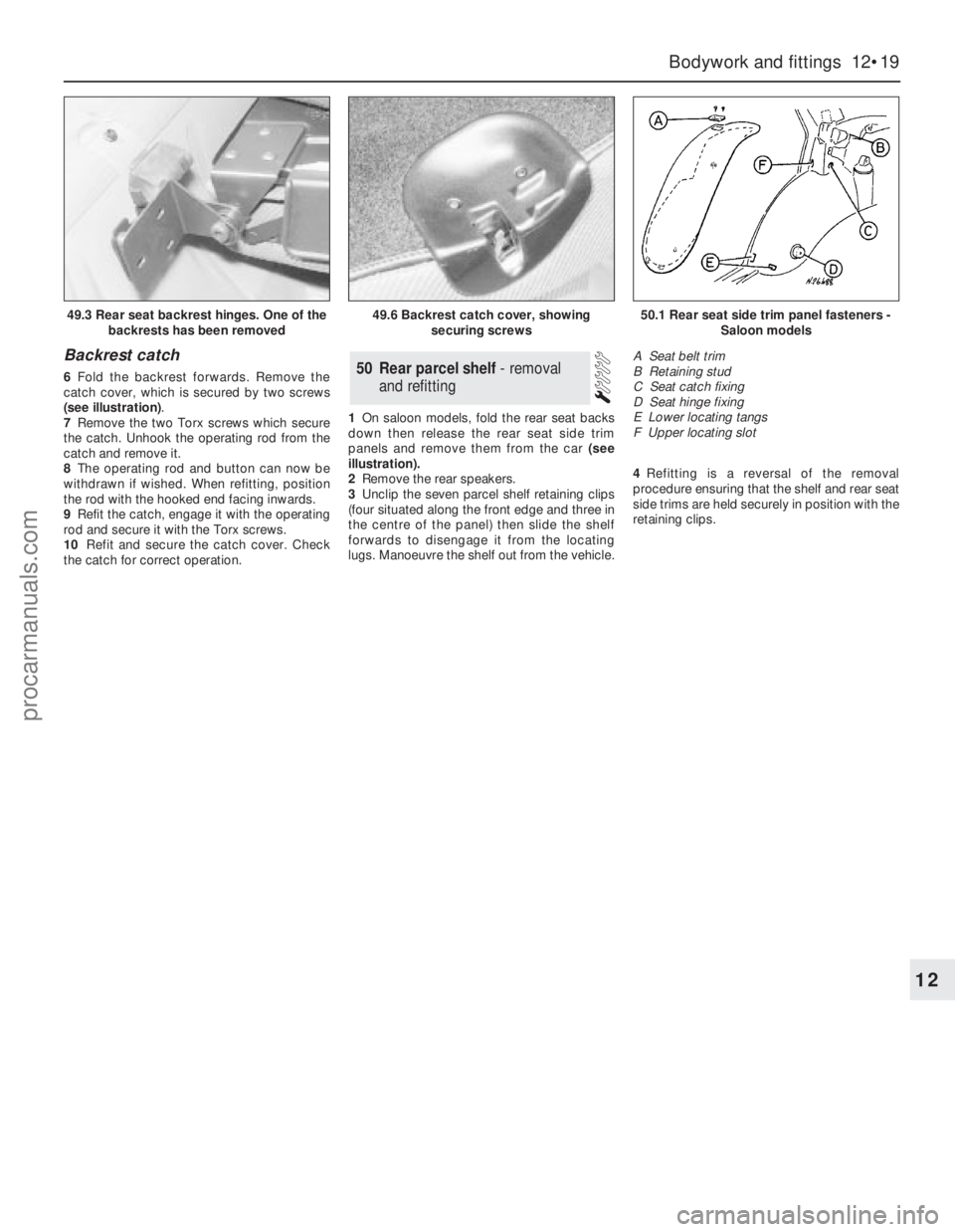
Backrest catch
6Fold the backrest forwards. Remove the
catch cover, which is secured by two screws
(see illustration).
7Remove the two Torx screws which secure
the catch. Unhook the operating rod from the
catch and remove it.
8The operating rod and button can now be
withdrawn if wished. When refitting, position
the rod with the hooked end facing inwards.
9Refit the catch, engage it with the operating
rod and secure it with the Torx screws.
10Refit and secure the catch cover. Check
the catch for correct operation.1On saloon models, fold the rear seat backs
down then release the rear seat side trim
panels and remove them from the car (see
illustration).
2Remove the rear speakers.
3Unclip the seven parcel shelf retaining clips
(four situated along the front edge and three in
the centre of the panel) then slide the shelf
forwards to disengage it from the locating
lugs. Manoeuvre the shelf out from the vehicle.4Refitting is a reversal of the removal
procedure ensuring that the shelf and rear seat
side trims are held securely in position with the
retaining clips.50Rear parcel shelf - removal
and refitting
Bodywork and fittings 12•19
12
49.3 Rear seat backrest hinges. One of the
backrests has been removed49.6 Backrest catch cover, showing
securing screws50.1 Rear seat side trim panel fasteners -
Saloon models
A Seat belt trim
B Retaining stud
C Seat catch fixing
D Seat hinge fixing
E Lower locating tangs
F Upper locating slot
procarmanuals.com