Page 33 of 38
 To ensure complete emptying of the canister,
hold the canister in position for one minute
after sound stops
If temperature is below -10°C (14")
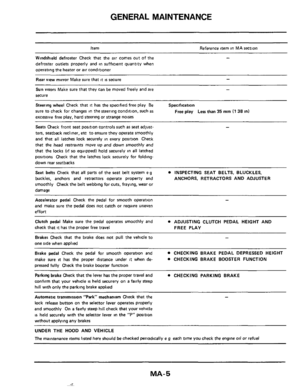
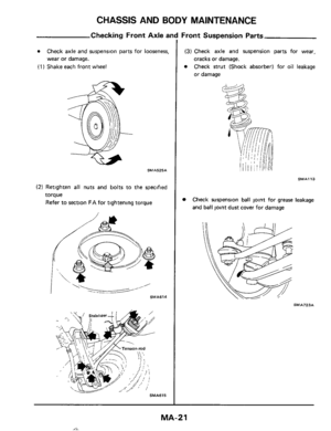
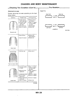
CHASSIS AND BODY MAINTENANCE
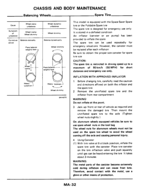
Spare Til
(2) To ensure complete emptying of the canister,
hold the canister in position for one minute
after sound stops
If temperature is below -10°C (14OF), the
canister must be warmed on
the windshield
defroster for five to ten minutes to provide
tire
inflation
b. In cold weather, the tire may not look fully
.inflated Therefore, drive slowly for the
first
mile, as the tire temperature rises the pressure
will mcrease.
a
Using Air Compressor
(1) Remove the valve cap from the spare tire and
securely connect the air pump hose in
its place
(2) Connect the power cord plug of the air pump
to the cigarette lighter socket The spare
tire
may be inflated to the recommended pressure
28 psi (200 kPa) in about 6 minutes Adjust
the
tire pressure per the tire placard with tire
pressure gauge
If the air pump operation is slow, run the engine
while the air pump is operating In this case,
remove jack with
the spare tire attached to the
axle.
WARNING:
0
0
Do not run the engine in closed space or with
the car being jacked up
Do not touch the air pump with the bare hands
while
it is operating for it may become quite
hot.
(3) Disconnect the power cord plug from socket
Check the
tire for air leakage, and then
securely install and tighten the valve cap
5 Lower car and fully tighten wheel nuts
Do not
install the wheel cover on the spare tire
DEFLATION
1 Deflate tire by depressing button on tire
inflation valve or by removing valve core
WARN1 NG.
To avoid personal injury, do not inhale the
gas
which is vented while the tire is deflating.
(Cont'd)
2 Flatten tire The spare tire becomes folded
3
REPAIR
Only qualified tire experts are authorized to
dismount the spare tire from
its rim or repair it in
any way Improper service can result
in serious
personal injury
Contact aumorized B.F. Goodrich dealers (for
Space Saver Spare tire)
or authorized Bridgestone
or DATSUN dealers (for Foldable Spare tire)
if
setvice is required.
iqradually while deflating
Store tire in rear compartment
MA-33
Page 34 of 38
CHASSIS AND BODY MAINTENANCE
Checking Steering Gear
and Linkage
SM A130A
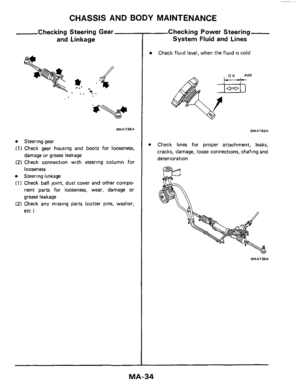
Steering gear
(1) Check gear housing and boots for looseness,
(2) Check connection with steering column for
Steering linkage
(1) Check ball joint, dust cover and other compo-
nent
parts for looseness, wear, damage or
grease leakage
(2) Check any missing parts (cotter pins, washer,
etc
)
damage or grease leakage
looseness
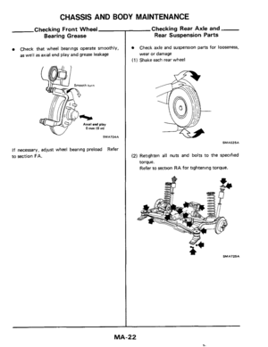
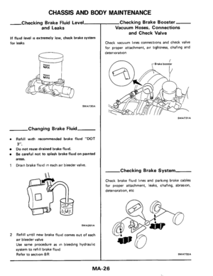
Checking Power Steering
System Fluid and Lines
Check fluid level, when the fluid is cold
SMA750A
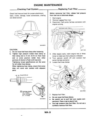
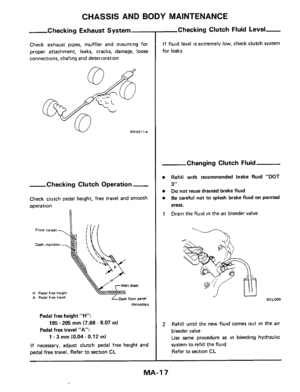
Check lines for proper attachment, leaks,
cracks, damage,
loose connections, chafing and
deterioration
SM A7 39A
MA-34
Page 35 of 38
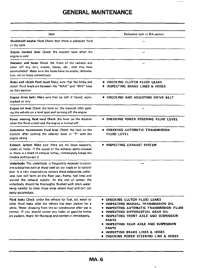
CHASSIS AND BODY MAINTENANCE
Body
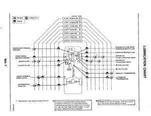
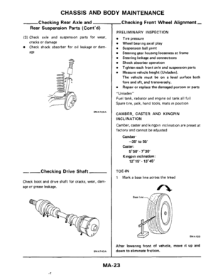
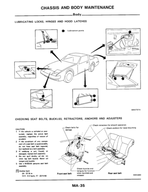
LUBRICATING LOCKS, HINGES AND HOOD LATCHES
CHECKING SEAT BELTS, BUCKLES, RETRACTORS, ANCHORS AND ADJUSTERS
CAUTION 1 If the vehicle IS collided or over
turned, replace the entire belt
assembly, regardless of
nature of
accident
2 If the condition of any compo- nent of a seat belt isquestionable.
do not have seat belt repaired,
but
replaced as a belt assembly
3 If webbmg IS cut. frayed. or
damaged. replace belt assembly
4 Do not spill drinks. 011 etc on inner lap belt buckle Never 011
tongue and buckle 5 use a NISSAN genuine seat belt
assembly
Anchor bolt
24-31Nm (2 4.3 2 kg-m, 17 - 23 ft-lbl
Check anchors for loose mounting
Check buckler and
tongues for function Front sat belt when buckled and Rear Seat belt released SMA443
MA-35
Page 36 of 38

Used belt deflection
Limit
Adlusted deflecraon
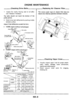
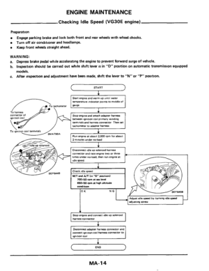
Engine Maintenance
INSPECTION AND ADJUSTMENT
st deflec. TIon Of
new belt Pedal free Play \"A\"
Alternat")
SERVICE DATA AND SPECIFICATIONS (S.D.S.)
Used belt deflection
Limit
Adlusted deflecraon
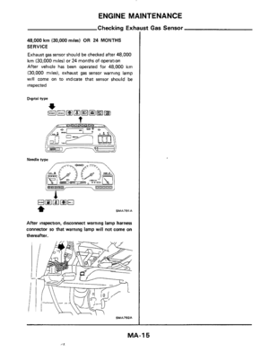
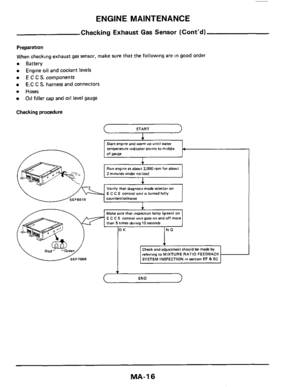
Engine Maintenance
INSPECTION AND ADJUSTMENT
st deflec. TIon Of
new belt Pedal free Play "A"
Alternator
1 -3 IO M -0 121
Arr conditioner I 16 I 9-11 I 7-9 compressor (0631 1035 0431 (028-0351
ADDlted pushtng force I 98 N 110 kg, 22 Ibl
21
10831 Power steering 011 pump
Oil capacity
13.16 10-13
1051 .0631 (039-0511 ~~
unlt P IUS qt. Imp qtl
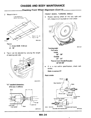
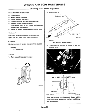
Wheel alignment IUnladenI
Camber
degree
Caster degree
-35' to 55'
5*50.7"30
Coolant capacity Unlt &? IUS qt. Imp qtl
Wlth 041 falter
Wtthout
001 filter
VG30E & VG30ET
4
0 (4-1 /4, 3-1/21
3 3 13-1/2.
2 7/81
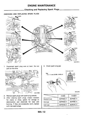
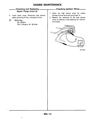
Spark plug
VG30E
I VG30E I VO3OET
105 111-1/8, 91/41
Front wheel turning angle Toe-out turns
Inner wheelIOufer wheel
degree
Plug uaD I 10- 1 1 mm 10039-OW3 in1
22"30'/20'
altitude I 20*2'/650t50 I 20t2'/650f50
standard iype
Hot type
Cola woe
condmon
VG30ET I 20 f 2"/700 f 50 I 20 + 2'/650 t 50
BCPR6ES.11 BCPR6E-11
BCPRSES.11 BCPRSE-11
BCPR7ES.11 BCPR7E-11
TIGHTENING TORQUE
U"lt Nm kg-m ft-lb
Full turns Inner wheel degree
Outer wheel degree
Or1 pan drain plug 29-39 30-40 22-29
Spark plug 20-29 20-30 14-22
Fuel hme clamps 10-15 010-015 07-11
35" .39"
27" .31'
-Chassis and Body Maintenance-
INSPECTION AND ADJUSTMENT
Clutch
Unlt mm 11nI
Pedal height "H" I 195 - 205 I7 68.8 071
Front axle and front suspension
Wheel bearmg preload
IAr measured at wheel hub bolt1 6 86.14 61
With used parts N Ikg, Ibl 1 1 67.7 75 IO 17-079.037- 1741
Kingpin mclination degree I 12'15'- 13'45
degree I 6'- 16
Out 3 (0 0361 - In 3 (0 0361 Side lip IReference datal mm/m lin/ftl
37 5 I1 476) Standard side rod length "A" mm bnl
* On power steering models, wheel turning force la1 circumference
afsteeringwheellof98-147NI10-15kg.22-33lblwith
engtne at idle
Rear axle and rear suspension
Camber degree I -1-55' fa -25
mm (4") I -2 to 2 1-0 08 to 0 081 Toe-,"
Page 37 of 38

Chassis and Body Maintenance (Contd)
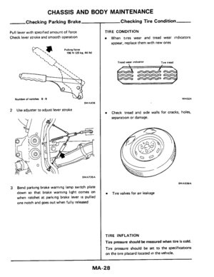
Parklng brake
[at
pulling force 196 N 120 kg. 44 Ibll
Number of notches
Brake Unit mm (mi
8-9
CL28V 2 0 10 0")
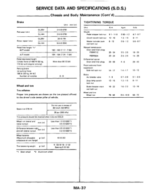
SERVICE DATA AND SPECIFICATIONS (S.D.S.)
Chassis and Body Maintenance (Cont'd)
Parklng brake
[at
pulling force 196 N 120 kg. 44 Ibll
Number of notches
Brake Unit mm (mi
8-9
CL28V 2 0 10 0791
Pad wear limit -+--- CL14H 2 0 10 0791
Difference between right
and left lateral
runout mm (In1
Rotor repair limit CL14H 9 0 (0 3541
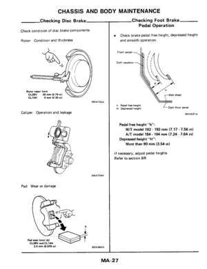
Pedal free hetght "h"
Mi7 model 182.192 (7 17.7 56)
Less than 0 5 (0 0201'1
0 2 10 0081'2
Pedal depressed height
[Under force
of 490 N 150 kg. 110 Ibl with englne running1 More than 90 13 541
Wheel and tire
Tire inflation
Proper tire pressures are shown on the tire placard affixed
to the driver's side center Dillar of vehicle.
80 km/h 150 MPH)
28 psi 1200 kPa1
Spare tire C78-14
T~re pressure should be checked when tires are COLD
Wheel rim lateral and
radial runout
1
Less than 1 0 10 0391'1 0 5 (0 020)*2 mm 11nl
Wheel balance IMaximvm allowable gr 102) 10 10 35)
unbalance at rim flange1
I 5-601018-2121 Spmng 5 10 181 Tire balancing weight gr 1oz)
I
*1 Steel wheel *2 Aluminum wheel
TIGHTENING TORQUE
Unit Nm
Clutch
Pedal stopper lock nut
Clutch switch lock
nut
Master cyhnder push 8. 12
rod lock nut
Manual transmission
9 1 - 11 8
12 - 15
Drain and filter plugs
FS5W71C 25 - 34
FS5R90A 20.34
Differential carrier
Front axle and front
S"Spe"Sl0"
Side rad lock nut
Drain and flller plugs 39 - 59
14.17
Brake Air bleeder value 7-9
Stop lamp swmh 12-15
lock nut
Brake booster input
rod lock
nut
16 - 22
Wheel and tire
Wheel nut 78.98
kg-m ft-lb
093.12 67-87
12-15 9-11
08-12 58-87
25-35 18-25
20-35 14-25
4-6 29 - 43
14-17 10-12
07-09 51-65
12-15 9-11
16-22 12-16
80.100 58-72
MA-37
Page 38 of 38
SPECIAL SERVICE TOOL
EG11150000
(-)
Tool name Tool number
(Kent-Moore
No I
Ignition coil adapter harness
MA-38
 Check gear housing and boots for looseness,
(2) Check connection with steering column for
Stee")


Tool name Tool number
(Kent-Moore
No I
Ignition coil adapter harness
MA-38")