1984 NISSAN 300ZX height
[x] Cancel search: heightPage 5 of 38
GENERAL MAINTENANCE
Item Reference item in MAsection
Windshield defroster Check that the air comes out of the
defroster outlets properly and in sufficient quantity when
operating the heater or
air conditioner
Rear view mirror Make sure that it is secure
-
-
Sun visors Make sure that they can be moved freely and are
secure
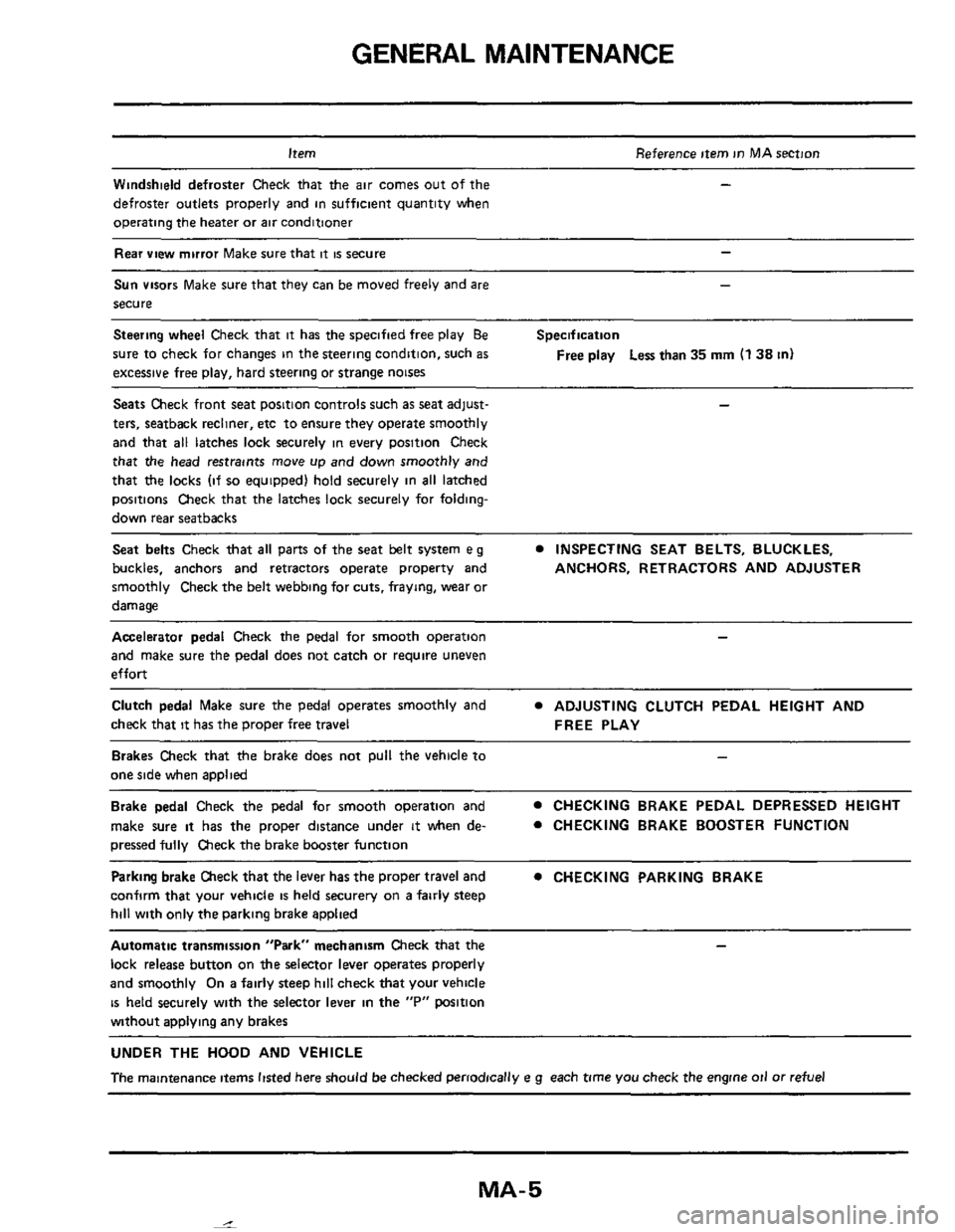
Steering wheel Check that it has the specified free play Be
sure to check for changes in the steering condition, such
as
excessive free play, hard steering or strange noises
-
Specification
Free
play Less than 35 mm (1 38 in)
Seats Check front seat position controls such as seat adjust- -
ters, seatback recliner, etc to ensure they operate smoothly
and that
all latches lock securely in every position Check
that the head restraints move up and down smoothly and
that
the locks (if so equipped) hold securely in all latched
positions Check that the latches lock securely for folding-
down rear seatbacks
Seat belts Check that all parts of the seat belt system e g
buckles, anchors and retractors operate property and ANCHORS, RETRACTORS AND ADJUSTER
smoothly Check the belt webbing for cuts, fraying, wear or
damage
INSPECTING SEAT BELTS, BLUCKLES,
Accelerator pedal Check the pedal for smooth operation -
and make sure the pedal does not catch or require uneven
effort
Clutch pedal Make sure the pedal operates smoothly and
check that
it has the proper free travel
ADJUSTING CLUTCH PEDAL HEIGHT AND
FREE PLAY
Brakes Check that the brake does not pull the vehicle to
one side when applied
Brake pedal Check the pedal for smooth operation and
make sure
it has the proper distance under it when de-
pressed fully Check the brake booster function
CHECKING BRAKE PEDAL DEPRESSED HEIGHT
0 CHECKING BRAKE BOOSTER FUNCTION
Parking brake Check that the lever has the proper travel and
confirm that your vehicle
is held securery on a fairly steep
hill with only the parking brake applied
0 CHECKING PARKING BRAKE
Automatic transmission "Park" mechanism Check that the
lock release button on the selector lever operates properly
and smoothly
On a fairly steep hill check that your vehicle
is held securely with the selector lever in the "P" wsition
without
aDDlvina anv brakes
UNDER THE HOOD AND VEHICLE
The maintenance items listed here should be checked periodically e g each time you check the engine oil or refuel
MA-5
Page 17 of 38
CHASSIS AND BODY MAINTENANCE
Checking Exhaust System
Check exhaust pipes, muffler and mounting for
proper attachment,
leaks, cracks, damage, loose
connections, chafing and deterioration
W SMA211A
-Checking Clutch Operation -
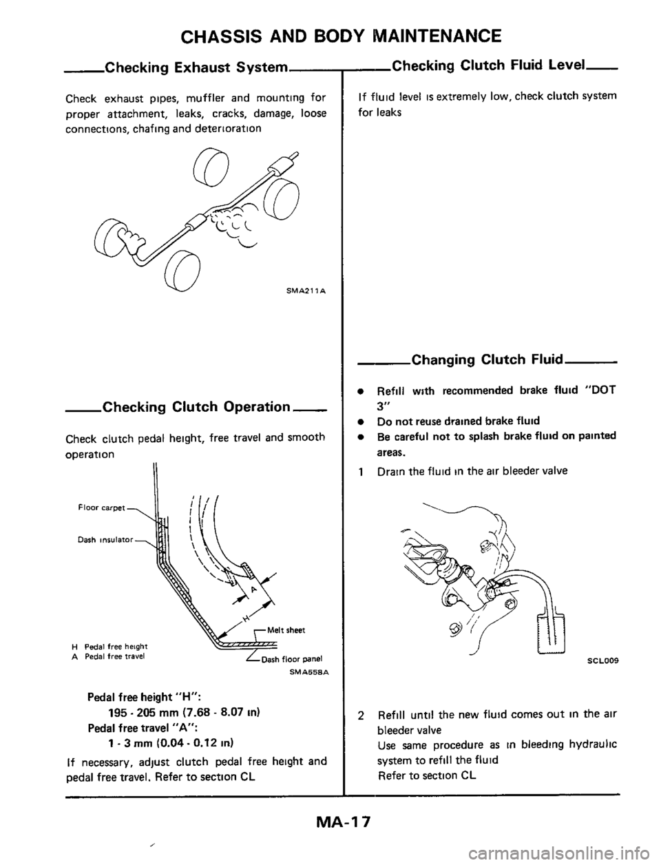
Check clutch pedal height, free travel and smooth
omration
Floor carpet
Dash insulator
H Pedal free height A Pedal free travel
SMA558A
Pedal free height "H":
Pedal free travel "A":
195.205 mm (7.68 - 8.07 in)
1 ~ 3 rnrn (0.04 - 0.12 in)
If necessary, adjust clutch pedal free height and
pedal free travel. Refer
to section CL
-Checking Clutch Fluid Level-
If fluid level is extremely low, check clutch system
for leaks
Changing Clutch Fluid
Refill with recommended brake fluid "DOT
3"
Do not reuse drained brake fluid
Be careful not to splash brake fluid on painted
areas.
Drain the fluid in the air bleeder valve
SCLOO9
Refill until the new fluid comes out in the air
bleeder valve
Use same procedure as in bleeding hydraulic
system to refill the fluid
Refer to section CL
MA-I 7
,
Page 23 of 38
CHASSIS AND BODY MAINTENANCE
Checking Rear Axle and
Rear Suspension Parts (Cont'd)
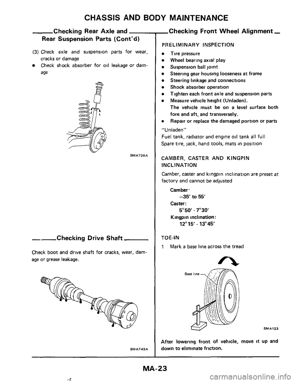
(3) Check axle and suspension parts for wear,
cracks or damage
0 Check shock absorber for oil leakage or dam-
age
- SMA726A
--Checking Drive Shaft
Check boot and drive shaft for cracks, wear, dam-
age or grease leakage.
SM A743 A
,Checking Front Wheel Alignment -
PRELIMINARY INSPECTION
Tire pressure
Wheel bearing axial play
Suspension ball joint
Steering linkage and connections
Shock absorber operation
Tighten each front axle and suspension parts
Measure vehicle height (Unladen).
The vehicle must be on a level surface both
fore and
aft, and transversely.
Repair or replace the damaged portion or
parts
Steering gear housing looseness at frame
" U n I aden "
Fuel tank, radiator and engine oil tank all full
Spare tire, lack, hand tools, mats in position
CAMBER, CASTER AND KINGPIN
INCLINATION
Camber, caster and kingpin inclination are preset
at
factory and cannot be adjusted
Camber.
-35 to 55'
Caster :
5"50 - 7"3Q
Kingpin inclination:
12"15' - 13"45'
TOE-IN
1 Mark a base line across the tread
After lowering front of vehicle, move it up and
down
to eliminate friction.
MA-23
4
Page 25 of 38
CHASSIS AND BODY MAINTENANCE
Checking Rear
PRELIMINARY INSPECTION
0 Tire pressure.
0 Wheel bearing axial play
0 Shock absorber operation.
0
0 Measure vehicle height (Unladen)
Tighten each rear axle and suspension part
The vehicle must be on a level surface both
fore and
aft, and laterally
Repair or replace the damaged portion or parts
0
"Unladen"
Fuel tank, radiator and engine oil tank all full
Spare
tire, jack, hand tools, mats in position
CAMBER
Camber
is preset at factory and cannot be adjusted
Camber:
-1"55'tO -25'
TOE-IN
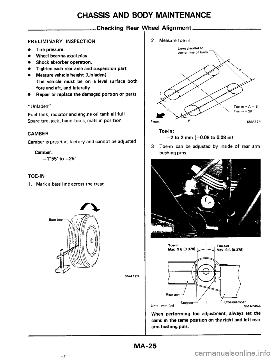
1. Mark a base line across the tread
SMA123
nee1 Alignment
2 Measure toe-in
~~ner parallel to center Ime of body-
Toe-in = A - B
, Front 8 SMA124
Toe-in:
-2 to 2 mm (-0.08 to 0.08 in)
3 Toein can be adjusted by inside of rear arm
bushing pins
Unit
Tobl" TObOltl Max 9 6 10 3781 Max 9.6 (0.378)
When performing toe adjustment, always set the
cams in the same position on the right and left rear
arm bushing pins.
MA-25
,,_l
Page 27 of 38
CHASSIS AND BODY MAINTENANCE
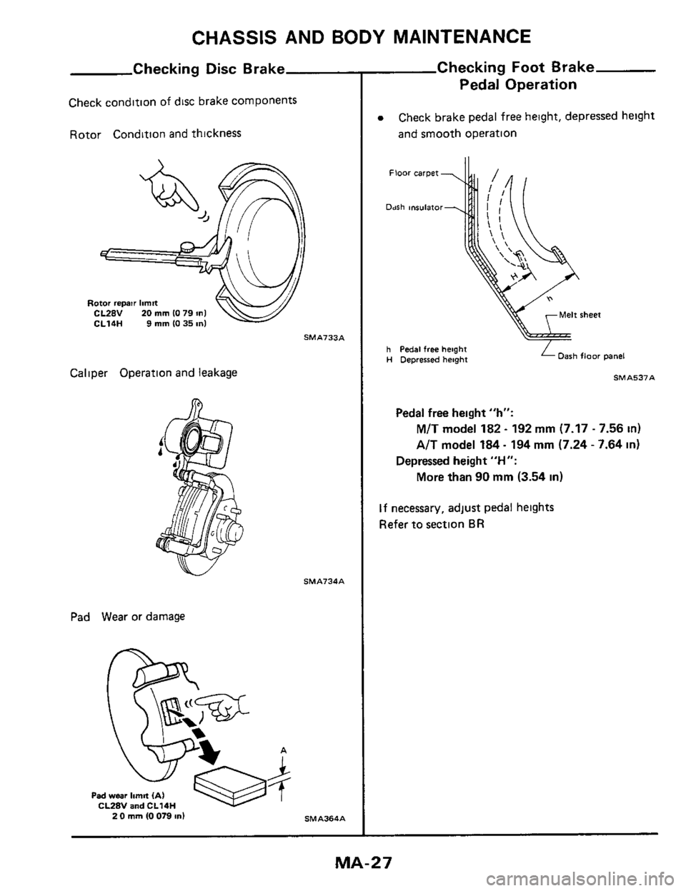
Checking Disc Brake
Check condltlon of disc brake components
Rotor Condition and thickness
Caliper Operation and leakage
Pad Wear or damage
SMA733A
SMA?34A
A
Checking Foot Brake
Pedal Operation
0 Check brake pedal free height, depressed height
and smooth operation
h Pedal free height H Depressed height Dash floor panel
Pedal free height "h":
M/T model 182 - 192 mm (7.17 - 7.56 in)
AlT model 184 - 194 mm (7.24 - 7.64 in)
More than 90 mm (3.54 in)
Depressed height "H":
If necessary, adjust pedal heights
Refer to section
BR
MA- 2 7
Page 36 of 38
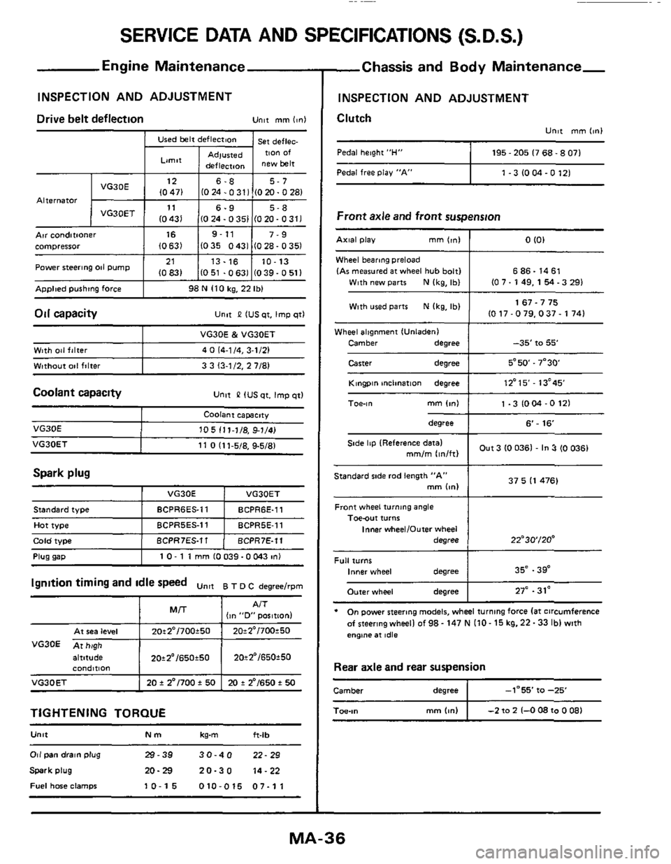
SERVICE DATA AND SPECIFICATIONS (S.D.S.)
Used belt deflection
Limit
Adlusted deflecraon
Engine Maintenance
INSPECTION AND ADJUSTMENT
st deflec. TIon Of
new belt Pedal free Play "A"
Alternator
1 -3 IO M -0 121
Arr conditioner I 16 I 9-11 I 7-9 compressor (0631 1035 0431 (028-0351
ADDlted pushtng force I 98 N 110 kg, 22 Ibl
21
10831 Power steering 011 pump
Oil capacity
13.16 10-13
1051 .0631 (039-0511 ~~
unlt P IUS qt. Imp qtl
Wheel alignment IUnladenI
Camber
degree
Caster degree
-35' to 55'
5*50.7"30
Coolant capacity Unlt &? IUS qt. Imp qtl
Wlth 041 falter
Wtthout
001 filter
VG30E & VG30ET
4
0 (4-1 /4, 3-1/21
3 3 13-1/2.
2 7/81
Spark plug
VG30E
I VG30E I VO3OET
105 111-1/8, 91/41
Front wheel turning angle Toe-out turns
Inner wheelIOufer wheel
degree
Plug uaD I 10- 1 1 mm 10039-OW3 in1
22"30'/20'
altitude I 20*2'/650t50 I 20t2'/650f50
standard iype
Hot type
Cola woe
condmon
VG30ET I 20 f 2"/700 f 50 I 20 + 2'/650 t 50
BCPR6ES.11 BCPR6E-11
BCPRSES.11 BCPRSE-11
BCPR7ES.11 BCPR7E-11
TIGHTENING TORQUE
U"lt Nm kg-m ft-lb
Full turns Inner wheel degree
Outer wheel degree
Or1 pan drain plug 29-39 30-40 22-29
Spark plug 20-29 20-30 14-22
Fuel hme clamps 10-15 010-015 07-11
35" .39"
27" .31'
-Chassis and Body Maintenance-
INSPECTION AND ADJUSTMENT
Clutch
Unlt mm 11nI
Pedal height "H" I 195 - 205 I7 68.8 071
Front axle and front suspension
Wheel bearmg preload
IAr measured at wheel hub bolt1 6 86.14 61
With used parts N Ikg, Ibl 1 1 67.7 75 IO 17-079.037- 1741
Kingpin mclination degree I 12'15'- 13'45
degree I 6'- 16
Out 3 (0 0361 - In 3 (0 0361 Side lip IReference datal mm/m lin/ftl
37 5 I1 476) Standard side rod length "A" mm bnl
* On power steering models, wheel turning force la1 circumference
afsteeringwheellof98-147NI10-15kg.22-33lblwith
engtne at idle
Rear axle and rear suspension
Camber degree I -1-55' fa -25
mm (4") I -2 to 2 1-0 08 to 0 081 Toe-,"
Page 37 of 38
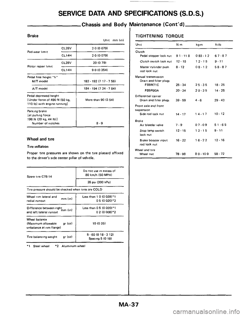
SERVICE DATA AND SPECIFICATIONS (S.D.S.)
Chassis and Body Maintenance (Cont'd)
Parklng brake
[at
pulling force 196 N 120 kg. 44 Ibll
Number of notches
Brake Unit mm (mi
8-9
CL28V 2 0 10 0791
Pad wear limit -+--- CL14H 2 0 10 0791
Difference between right
and left lateral
runout mm (In1
Rotor repair limit CL14H 9 0 (0 3541
Pedal free hetght "h"
Mi7 model 182.192 (7 17.7 56)
Less than 0 5 (0 0201'1
0 2 10 0081'2
Pedal depressed height
[Under force
of 490 N 150 kg. 110 Ibl with englne running1 More than 90 13 541
Wheel and tire
Tire inflation
Proper tire pressures are shown on the tire placard affixed
to the driver's side center Dillar of vehicle.
80 km/h 150 MPH)
28 psi 1200 kPa1
Spare tire C78-14
T~re pressure should be checked when tires are COLD
Wheel rim lateral and
radial runout
1
Less than 1 0 10 0391'1 0 5 (0 020)*2 mm 11nl
Wheel balance IMaximvm allowable gr 102) 10 10 35)
unbalance at rim flange1
I 5-601018-2121 Spmng 5 10 181 Tire balancing weight gr 1oz)
I
*1 Steel wheel *2 Aluminum wheel
TIGHTENING TORQUE
Unit Nm
Clutch
Pedal stopper lock nut
Clutch switch lock
nut
Master cyhnder push 8. 12
rod lock nut
Manual transmission
9 1 - 11 8
12 - 15
Drain and filter plugs
FS5W71C 25 - 34
FS5R90A 20.34
Differential carrier
Front axle and front
S"Spe"Sl0"
Side rad lock nut
Drain and flller plugs 39 - 59
14.17
Brake Air bleeder value 7-9
Stop lamp swmh 12-15
lock nut
Brake booster input
rod lock
nut
16 - 22
Wheel and tire
Wheel nut 78.98
kg-m ft-lb
093.12 67-87
12-15 9-11
08-12 58-87
25-35 18-25
20-35 14-25
4-6 29 - 43
14-17 10-12
07-09 51-65
12-15 9-11
16-22 12-16
80.100 58-72
MA-37