Page 2 of 38

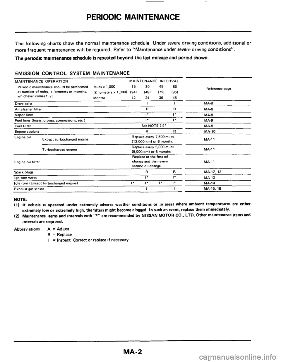
PERIODIC MAINTENANCE
The following charts show the normal malntenance schedule Under severe driving conditions, additional or
more frequent maintenance
w~ll be required. Refer to "Maintenance under severe driving conditions".
The periodic maintenance schedule
is repeated beyond the last mileage and period shown.
EMISSION CONTROL SYSTEM MAINTENANCE
MAINTENANCE OPERATION MAINTENANCE INTERVAL
Pertodc rnantenance should be performed Miles x 1,000 15 30 45 60
at number of miles. kilometers or months. (K,lometerr x 1.0001 (241 (481 (721 (961
Months 12 24 36 48
whichever comer first
Reference
Page
Orwe belts I I MA-8
Air cleaner filter R R MA-8
Vapor hnes 1. If MA4
Fuel lines (hoses. piping. connections. etc ) If if MA-9
Fuel filter See NOTE (11. MA-9
Englne coolant R R MA-10
MA-1 1
Engine 081
MA-1
1
Replace every 7.500 mile6
(12.000 kml or6 months
Replace every 5,000
miles
18.000 kmJ or 6 months
Replace
at the first 011
Except turbocharged engine
Turbocharged engine
Ewne 011 f,lter change and then every MA-1 1 second od change
Spark plugs R R MA-12. 13
I"",..""
Exhaust gas sensor I I MA-15. 16
NOTE:
(1) If vehicle is operated under extremely adverse weather conditions or in areas where ambient temperatures are either
extremely
low or extremely high, the filters mlght become clogged. In such an event, replke them immediately.
(2) Maintenance Items and antervals wlth "*" are recommended by NISSAN MOTOR CO., LTD. Other maintenance items and
intervals
are required.
Abbreviations A = Adjust
R =Replace
I = Inspect Correct or replace if necessary
MA-2
.
Page 9 of 38

ENGINE MAINTENANCE
Checking Fuel System
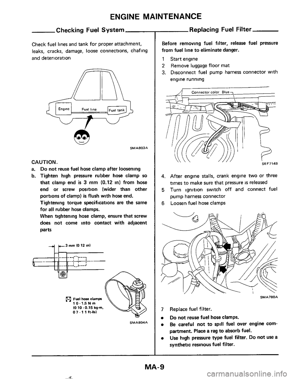
Check fuel lines and tank for proper attachment,
leaks, cracks, damage,
loose connections, chafing
and deterioration
SMA803A
CAUTION.
a. Do not reuse fuel hose clamp after loosening
b. Tighten high pressure rubber hose clamp
so
that clamp end is 3 mm (0.12 in) from hose
end or screw position (wider than other
portions of clamp)
is flush with hose end.
Tightening torque specifications are the same
for all rubber hose clamps.
When tightening hose clamp, ensure that screw
does not come into contact with adjacent
parts
10-1dNm IO 10 -0.15 kgm. 07 - 1 1 h-lbl
SMAS04A
Replacing Fuel Filter
Before removing fuel filter, release fuel pressure
from fuel line
to eliminate danger.
1 Start engine
2 Remove luggage floor mat
3. Disconnect fuel pump harness connector with
engine running
SEF7148
4. After engine stalls, crank engine two or three
times to make sure that pressure
is released
5 Turn ignition switch off and connect fuel
pump harness connector
6 Loosen fuel hose clamps
SMA780A
7 Replace fuel filter.
Do not reuse fuel hose clamps.
Be careful not to spill fuel over engine com-
partment. Place a rag
to absorb fuel.
Use high pressure type fuel filter. Do not use a
synthetic resinous
fuel filter.
MA-9
I
Page 36 of 38

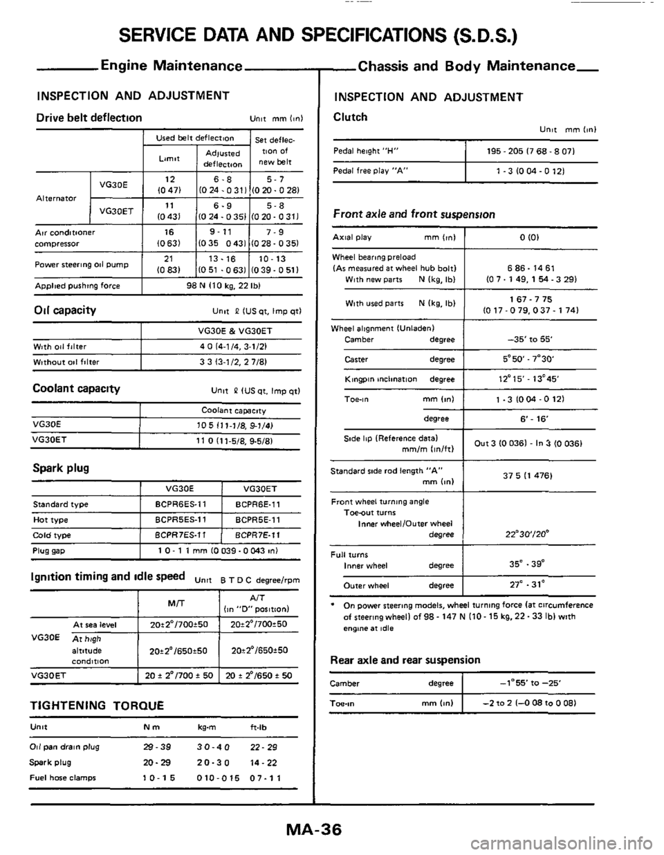
SERVICE DATA AND SPECIFICATIONS (S.D.S.)
Used belt deflection
Limit
Adlusted deflecraon
Engine Maintenance
INSPECTION AND ADJUSTMENT
st deflec. TIon Of
new belt Pedal free Play "A"
Alternator
1 -3 IO M -0 121
Arr conditioner I 16 I 9-11 I 7-9 compressor (0631 1035 0431 (028-0351
ADDlted pushtng force I 98 N 110 kg, 22 Ibl
21
10831 Power steering 011 pump
Oil capacity
13.16 10-13
1051 .0631 (039-0511 ~~
unlt P IUS qt. Imp qtl
Wheel alignment IUnladenI
Camber
degree
Caster degree
-35' to 55'
5*50.7"30
Coolant capacity Unlt &? IUS qt. Imp qtl
Wlth 041 falter
Wtthout
001 filter
VG30E & VG30ET
4
0 (4-1 /4, 3-1/21
3 3 13-1/2.
2 7/81
Spark plug
VG30E
I VG30E I VO3OET
105 111-1/8, 91/41
Front wheel turning angle Toe-out turns
Inner wheelIOufer wheel
degree
Plug uaD I 10- 1 1 mm 10039-OW3 in1
22"30'/20'
altitude I 20*2'/650t50 I 20t2'/650f50
standard iype
Hot type
Cola woe
condmon
VG30ET I 20 f 2"/700 f 50 I 20 + 2'/650 t 50
BCPR6ES.11 BCPR6E-11
BCPRSES.11 BCPRSE-11
BCPR7ES.11 BCPR7E-11
TIGHTENING TORQUE
U"lt Nm kg-m ft-lb
Full turns Inner wheel degree
Outer wheel degree
Or1 pan drain plug 29-39 30-40 22-29
Spark plug 20-29 20-30 14-22
Fuel hme clamps 10-15 010-015 07-11
35" .39"
27" .31'
-Chassis and Body Maintenance-
INSPECTION AND ADJUSTMENT
Clutch
Unlt mm 11nI
Pedal height "H" I 195 - 205 I7 68.8 071
Front axle and front suspension
Wheel bearmg preload
IAr measured at wheel hub bolt1 6 86.14 61
With used parts N Ikg, Ibl 1 1 67.7 75 IO 17-079.037- 1741
Kingpin mclination degree I 12'15'- 13'45
degree I 6'- 16
Out 3 (0 0361 - In 3 (0 0361 Side lip IReference datal mm/m lin/ftl
37 5 I1 476) Standard side rod length "A" mm bnl
* On power steering models, wheel turning force la1 circumference
afsteeringwheellof98-147NI10-15kg.22-33lblwith
engtne at idle
Rear axle and rear suspension
Camber degree I -1-55' fa -25
mm (4") I -2 to 2 1-0 08 to 0 081 Toe-,"