1984 NISSAN 300ZX coolant
[x] Cancel search: coolantPage 2 of 38
PERIODIC MAINTENANCE
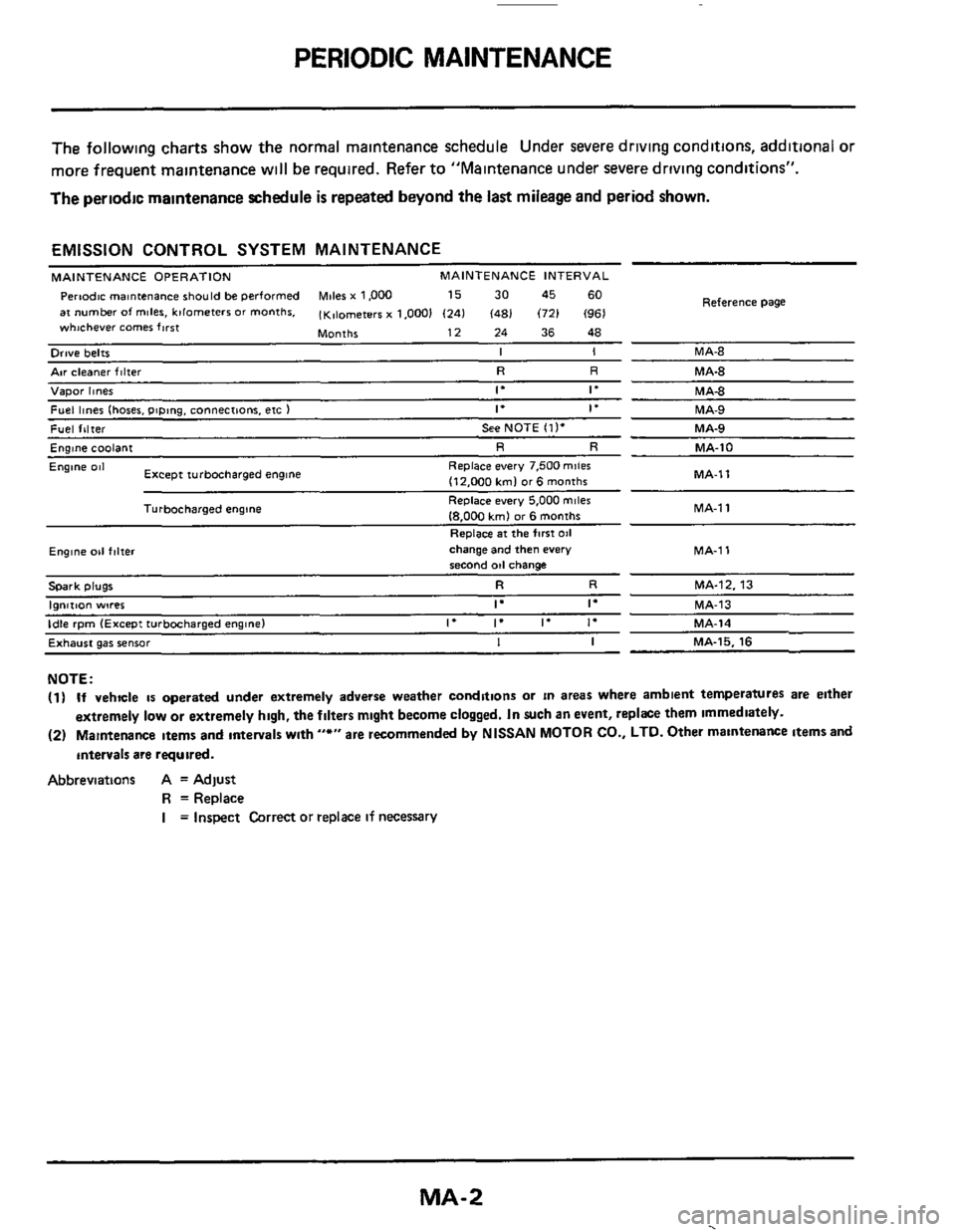
The following charts show the normal malntenance schedule Under severe driving conditions, additional or
more frequent maintenance
w~ll be required. Refer to "Maintenance under severe driving conditions".
The periodic maintenance schedule
is repeated beyond the last mileage and period shown.
EMISSION CONTROL SYSTEM MAINTENANCE
MAINTENANCE OPERATION MAINTENANCE INTERVAL
Pertodc rnantenance should be performed Miles x 1,000 15 30 45 60
at number of miles. kilometers or months. (K,lometerr x 1.0001 (241 (481 (721 (961
Months 12 24 36 48
whichever comer first
Reference
Page
Orwe belts I I MA-8
Air cleaner filter R R MA-8
Vapor hnes 1. If MA4
Fuel lines (hoses. piping. connections. etc ) If if MA-9
Fuel filter See NOTE (11. MA-9
Englne coolant R R MA-10
MA-1 1
Engine 081
MA-1
1
Replace every 7.500 mile6
(12.000 kml or6 months
Replace every 5,000
miles
18.000 kmJ or 6 months
Replace
at the first 011
Except turbocharged engine
Turbocharged engine
Ewne 011 f,lter change and then every MA-1 1 second od change
Spark plugs R R MA-12. 13
I"",..""
Exhaust gas sensor I I MA-15. 16
NOTE:
(1) If vehicle is operated under extremely adverse weather conditions or in areas where ambient temperatures are either
extremely
low or extremely high, the filters mlght become clogged. In such an event, replke them immediately.
(2) Maintenance Items and antervals wlth "*" are recommended by NISSAN MOTOR CO., LTD. Other maintenance items and
intervals
are required.
Abbreviations A = Adjust
R =Replace
I = Inspect Correct or replace if necessary
MA-2
.
Page 6 of 38
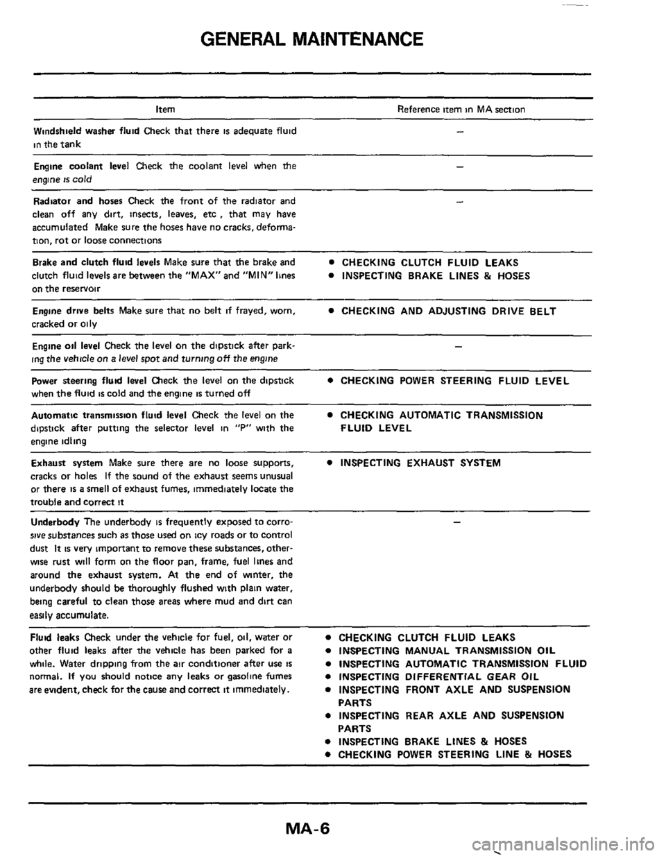
GENERAL MAINTENANCE
Item
Windshield washer fluid Check that there
is adequate fluid
in the tank
Reference item in MA section
-
Engine coolant level Check the coolant level when the -
engine is cold
Radiator and hoses Check the front of the radiator and
clean off any dirt, insects,
leaves, etc , that may have
accumulated Make sure the hoses have no cracks, deforrna-
tion, rot or loose connections
Brake and clutch fluid levels Make sure that the brake and CHECKING CLUTCH FLUID LEAKS
clutch fluid
levels are between the "MAX" and "MIN" lines INSPECTING BRAKE LINES & HOSES
on the reservoir
Engine drwe belts Make sure that no belt if frayed, worn,
cracked or oily CHECKING AND ADJUSTING DRIVE BELT
Engine oil level Check the level on the dipstick after park- -
ing the vehicle on a level spot and turning off the engine
Power steering fluid level Check the level on the dipstick
when the fluid
is cold and the engine is turned off
0 CHECKING POWER STEERING FLUID LEVEL
Automatic transmission fluid level Check the level on the CHECKING AUTOMATIC TRANSMISSION
dipstick after putting the selector
level in "P" with the FLUID LEVEL
engine idling
Exhaust system Make sure there are no loose supports, 0 INSPECTING EXHAUST SYSTEM
cracks or holes If the sound of the exhaust seems unusual
or there
is a smell of exhaust fumes, immediately locate the
trouble and correct
it
Underbody The underbody is frequently exposed to corro-
sive substances such as those used on icy roads or to control
dust
It is very impOrtant to remove these substances, other-
wise rust will form on the floor pan, frame, fuel lines and
around
the exhaust system. At the end of winter, the
underbody should be thoroughly flushed with plain water,
being careful to clean those
areas where mud and dirt can
easily accumulate.
Fluid leaks Check under the vehicle for fuel, oil, water or
other fluid
leaks after the vehicle has been parked for a 0 INSPECTING MANUAL TRANSMISSION OIL
while.
Water dripping from the air conditioner after use is 0 INSPECTING AUTOMATIC TRANSMISSION FLUID
normal. If you should notice
any leaks or gasoline fumes
are evident, check for
the cause and correct it immediately.
0 CHECKING CLUTCH FLUID LEAKS
0 INSPECTING DIFFERENTIAL GEAR OIL
0 INSPECTING FRONT AXLE AND SUSPENSION
0 INSPECTING REAR AXLE AND SUSPENSION
0 INSPECTING BRAKE LINES & HOSES
0 CHECKING POWER STEERING LINE & HOSES
PARTS
PARTS
MA-6
Page 7 of 38
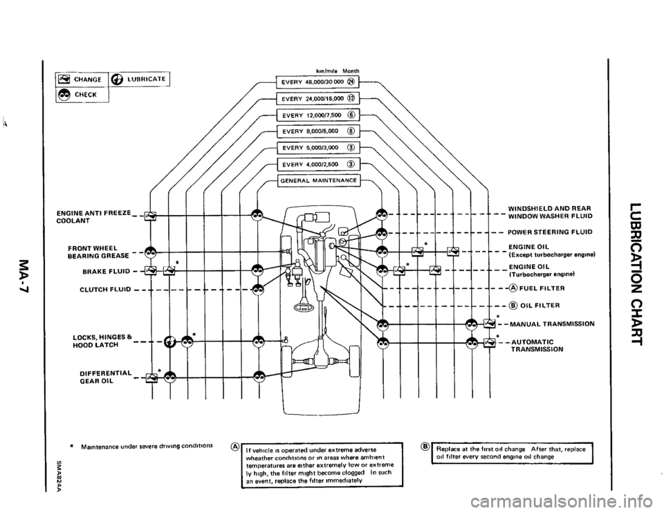
kmlmils Month
ENGINE ANTI FREEZE- - COOLANT
FRONT WHEEL
BEARING GREASE -
BRAKE FLUID -
DIFFERENTIAL - GEAR OIL
* Maintenance under severe driving condittons
z
tl
:
h)
whsather conditions or in areas where ambient
temperatures are either extremely low or extreme ly high, the filter might becomeclogged In such
, -1 --I-- 4 - -1 - t WINDSHIELD AND REAR
WINDOW WASHER FLUID --
-/---l--]--t-]-- POWERSTEERINGFLUID
w-1 --I- -ENGINE OIL (Except turbocharger engine)
- - @) OIL FILTER
*
--MANUAL TRANSMISSION
--AUTOMATIC
TRANSMISSION
@ Replace at the first 011 change After that. replace 011 filter every second engine 011 change
Page 10 of 38
ENGINE MAINTENANCE
Changing Ei
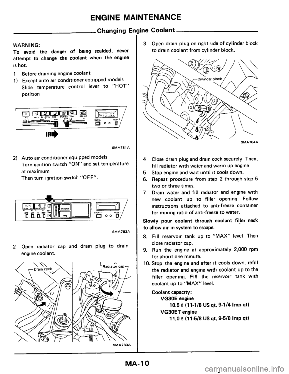
WARNING:
To avoid the danger of being scalded, never
attempt to change the coolant when the engine
is hot.
1 Before drainmg engine coolant
1) Except auto air conditioner equipped models
Slide temperature control lever to
"HOT"
position
SMAJ81 A
2) Auto air conditioner equipped models
Turn ignition switch
"ON" and set temperature
at maximum
Then turn ignition switch
"OFF".
SMA782A
2 Open radiator cap and drain plug to drain
engine coolant.
SMA703A
ine Coolant
3 Open drain plug on right side of cylinder block
to drain coolant from cylinder block.
4 Close drain plug and drain cock securely Then,
fill radiator with water and warm up engine
5 Stop engine and wait until it cools down.
6. Repeat procedure from step 2 through step 5
two or three times.
7 Drain water and fill radiator and engine with
new coolant up to
filler opening Follow
instructions attached to anti-freeze container
for
mixing ratio of anti-freeze to water.
Slowly pour coolant through coolant fryer neck
to allow air in system to escape.
8. Fill reservoir tank up to "MAX" level Then
close radiator cap.
9. Run the engine at approximately 2,000 rpm
for about one minute.
IO. Stop the engine and after it cools down, refill
the radiator
and engine with coolant up to the
filler opening. Fill the reservoir tank with
coolant up to "MAX" level.
Coolant capacity:
VG30E engine
VG30ET engine
10.5 P (11-1/8 US qt, 9-1/4 Imp qt)
11.0 P (1 1-5/8 US qt, 9-5/8 Imp qt)
MA-1 0
Page 16 of 38
ENGINE MAINTENANCE
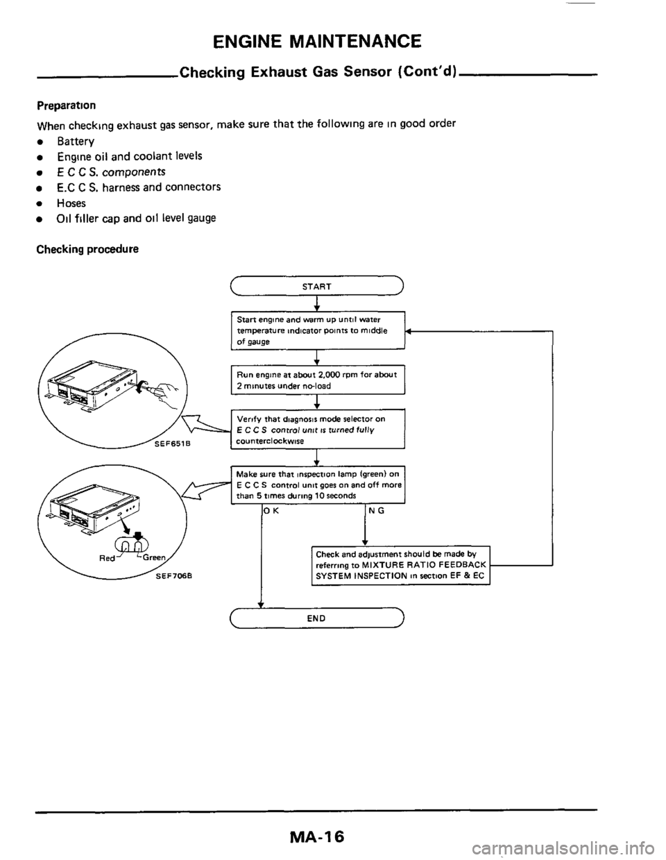
Checking Exhaust Gas Sensor (Cont'd)
Preparation
When checking exhaust gas sensor, make sure that the following are
in good order
0 Battery
0 Hoses
Engine oil and coolant levels
E C C S. components
E.C C S. harness and connectors
Oil filler cap and oil level gauge
Checking procedure
START
Stan engine and warm UP until water
temperature indicator Points
IO middle
of gauge
I +
Run engine at about 2.000 rpm for abut
2 minutes under noload
I
E C C S control unit is turned fully
referring to MIXTURE RA
MA-1 6
Page 36 of 38
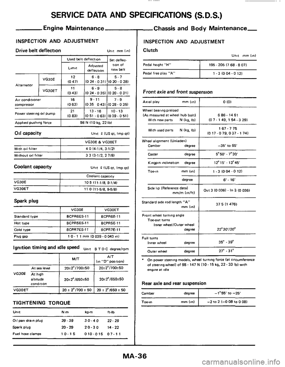
SERVICE DATA AND SPECIFICATIONS (S.D.S.)
Used belt deflection
Limit
Adlusted deflecraon
Engine Maintenance
INSPECTION AND ADJUSTMENT
st deflec. TIon Of
new belt Pedal free Play "A"
Alternator
1 -3 IO M -0 121
Arr conditioner I 16 I 9-11 I 7-9 compressor (0631 1035 0431 (028-0351
ADDlted pushtng force I 98 N 110 kg, 22 Ibl
21
10831 Power steering 011 pump
Oil capacity
13.16 10-13
1051 .0631 (039-0511 ~~
unlt P IUS qt. Imp qtl
Wheel alignment IUnladenI
Camber
degree
Caster degree
-35' to 55'
5*50.7"30
Coolant capacity Unlt &? IUS qt. Imp qtl
Wlth 041 falter
Wtthout
001 filter
VG30E & VG30ET
4
0 (4-1 /4, 3-1/21
3 3 13-1/2.
2 7/81
Spark plug
VG30E
I VG30E I VO3OET
105 111-1/8, 91/41
Front wheel turning angle Toe-out turns
Inner wheelIOufer wheel
degree
Plug uaD I 10- 1 1 mm 10039-OW3 in1
22"30'/20'
altitude I 20*2'/650t50 I 20t2'/650f50
standard iype
Hot type
Cola woe
condmon
VG30ET I 20 f 2"/700 f 50 I 20 + 2'/650 t 50
BCPR6ES.11 BCPR6E-11
BCPRSES.11 BCPRSE-11
BCPR7ES.11 BCPR7E-11
TIGHTENING TORQUE
U"lt Nm kg-m ft-lb
Full turns Inner wheel degree
Outer wheel degree
Or1 pan drain plug 29-39 30-40 22-29
Spark plug 20-29 20-30 14-22
Fuel hme clamps 10-15 010-015 07-11
35" .39"
27" .31'
-Chassis and Body Maintenance-
INSPECTION AND ADJUSTMENT
Clutch
Unlt mm 11nI
Pedal height "H" I 195 - 205 I7 68.8 071
Front axle and front suspension
Wheel bearmg preload
IAr measured at wheel hub bolt1 6 86.14 61
With used parts N Ikg, Ibl 1 1 67.7 75 IO 17-079.037- 1741
Kingpin mclination degree I 12'15'- 13'45
degree I 6'- 16
Out 3 (0 0361 - In 3 (0 0361 Side lip IReference datal mm/m lin/ftl
37 5 I1 476) Standard side rod length "A" mm bnl
* On power steering models, wheel turning force la1 circumference
afsteeringwheellof98-147NI10-15kg.22-33lblwith
engtne at idle
Rear axle and rear suspension
Camber degree I -1-55' fa -25
mm (4") I -2 to 2 1-0 08 to 0 081 Toe-,"