1984 NISSAN 300ZX tires
[x] Cancel search: tiresPage 4 of 38
GENERAL MAINTENANCE
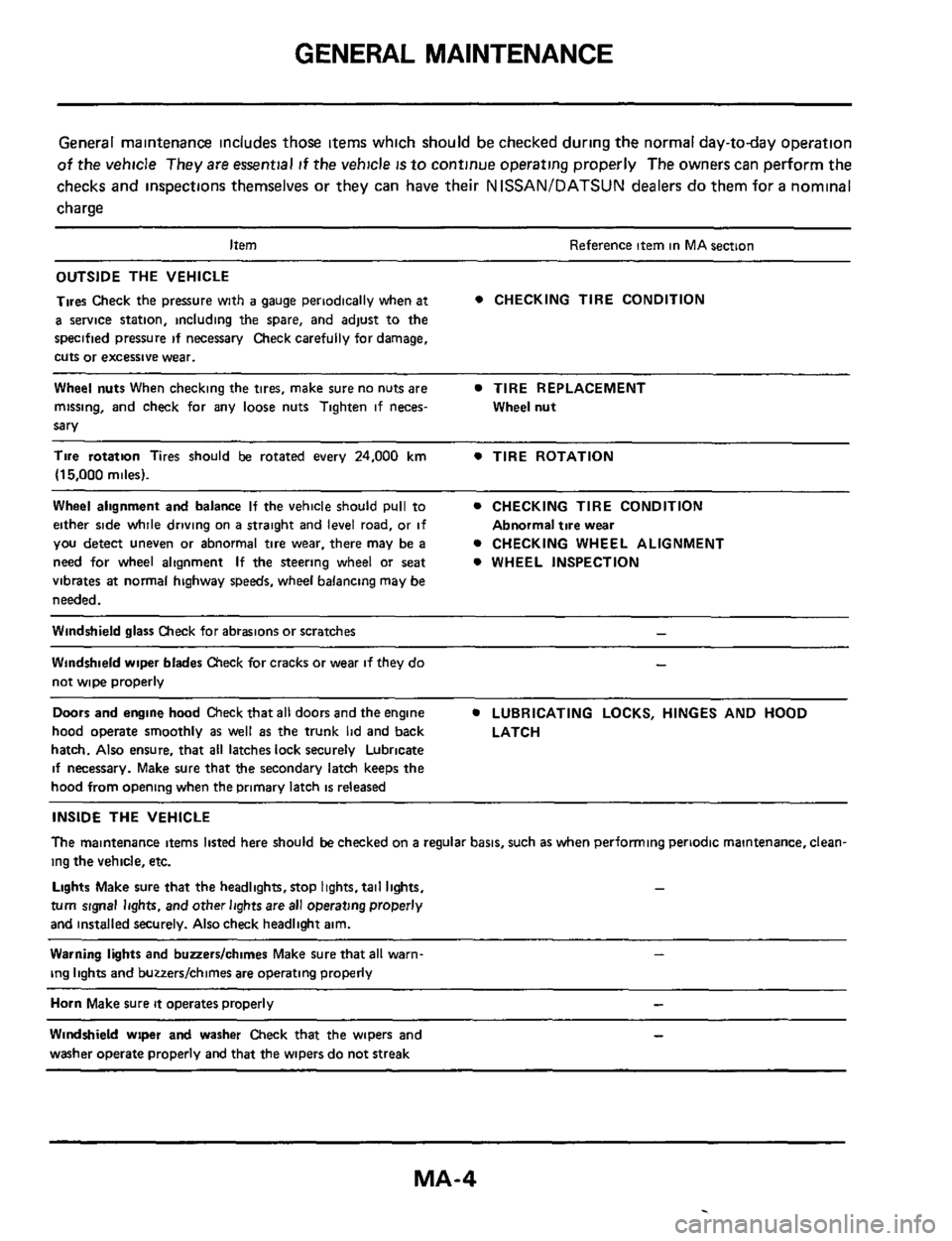
General maintenance includes those items which should be checked during the normal day-today operation
of the vehicle They are essential if the vehicle is to continue operating properly The owners can perform the
checks and inspections themselves
or they can have their N ISSAN/DATSUN dealers do them for a nominal
charge
Item Reference item in MA section
OUTSIDE THE VEHICLE
Tires Check the pressure with
a gauge periodically when at
a service station, including the spare, and adjust to the
specified pressure
if necessary Check carefully for damage,
cuts
or excessive wear.
Wheel nuts When checking the tires, make sure no nuts are TIRE REPLACEMENT
missing, and check for any loose nuts Tighten if neces-
sary
0 CHECKING TIRE CONDITION
Wheel nut
Tire rotation Tires should be rotated every 24.000 km 0 TIRE ROTATION
(15,000 miles).
Wheel alignment and balance If the vehicle should pull to 0 CHECKING TIRE CONDITION
either side while driving on
a straight and level road, or if
you detect uneven or abnormal tire wear, there may be a 0 CHECKING WHEEL ALIGNMENT
need for wheel alignment
If the steering wheel or seat 0 WHEEL INSPECTION
vibrates
at normal highway speeds, wheel balancing may be
needed.
Abnormal tire wear
Windshield glass Check for abrasions or scratches -
Windshield wiper blades Check for cracks or wear if they do
not wipe properly
Doors and engine hood Check that all doors and the engine
hood operate smoothly
as well as the trunk lid and back
hatch.
Also ensure, that all latches lock securely Lubricate
if necessary. Make sure that the secondary latch keeps the
hood from opening when the primary latch
is released
-
0 LUBRICATING LOCKS, HINGES AND HOOD
LATCH
INSIDE THE VEHICLE
The maintenance items listed here should be checked on a regular basis, such as when performing periodic maintenance, clean-
ing
the vehicle, etc.
turn signal lights. and other lights are all operating properly
and installed securely.
Also check headlight aim.
Lights Make sure that the headlights,stop lights. tail lights. -
Warning lights and buaerslchimes Make sure that all warn-
ing lights and buzzers/chimes are operating properly
Horn Make sure it operates properly -
Windshield wrper and washer Check that the wipers and
washer operate properly and that the wipers do not streak
Page 28 of 38
CHASSIS AND BODY MAINTENANCE
Checking Parking Brake
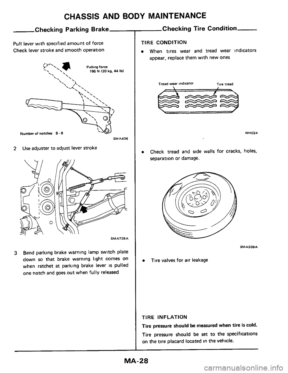
Pull lever with specified amount of force
Check lever stroke and smooth operation
Pullmg force . 196 N I20 kg. 44 Ibl
\' \ \' '
Number of notches 8 -9
SMA436
2 Use adjuster to adjust lever stroke
SMAl35A
3 Bend parking brake warning lamp switch plate
down
so that brake warning light comes on
when ratchet
at parking brake lever IS pulled
one notch and goes out when
fully released
Checking Tire Condition
TIRE CONDITION
0 When tires wear and tread wear indicators
appear, replace them with new ones
Tread wear indicaror Tire iread
WHO24
0 Check tread and side walls for cracks, holes,
separation or damage.
SMAS39A
0 Tire valves for air leakage
TIRE INFLATION
Tire
pressure should be measured when tire is cold.
Tire pressure should be
set to the specifications
on the tire placard located in the vehicle.
Page 29 of 38
CHASSIS AND BODY MAINTENANCE
,Checking Tire Condition (Cont'd)-
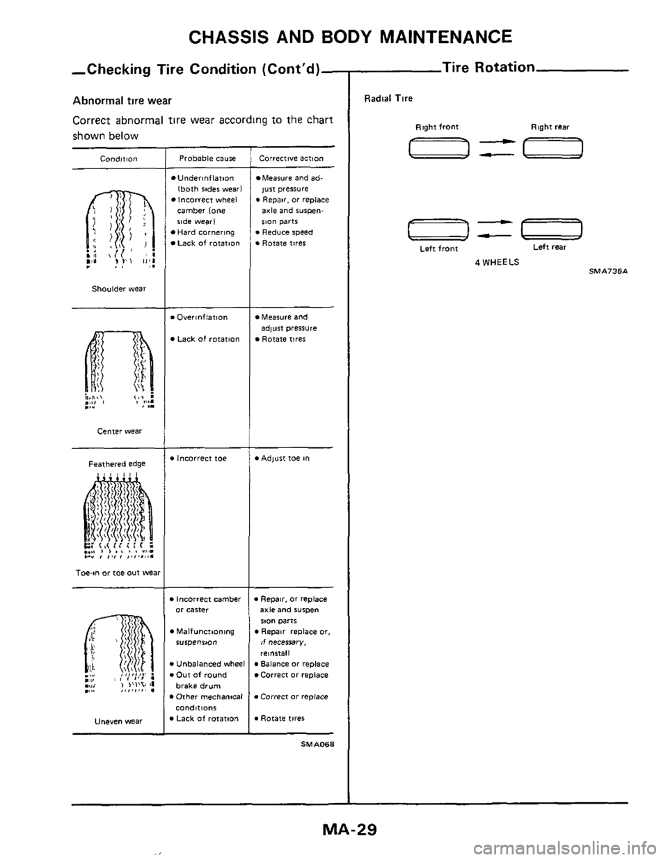
Abnormal tire wear
Correct abnormal tire wear according to the chart
shown below
Condition
Shoulder wear
Center wear
Feathered edge
Toe-in or toe out wea
Uneven Wear
Probable cause
Underinflation
lboth sides wear) Incorrect wheel
camber lone side wear1 Hard cornering
Lack of rotation
. Overlnflatlon
Lack of rotation
.Incorrect toe
rn Incorrect camber or carter
Malfunctioning rurpenrm
v Unbalanced wheel v Our of round
brake drum
Other mechantcal conditions Lack Of rotation
Corrective actton
Measure and ad-
just pressure . Repar. or replace
axle and rurpen- IlO" parts
.Reduce speed . Rotate tires
Measure and
Rotate tires
adlust pressure
*Adlust toe In
Repa~r. or replace axle and iuwm
SlO" parts
If necessary.
rel"6tall
Repar replace or,
m Balance or replace Correct or replace
m Correct or replace
v Rotate tires
SMA068
Tire Rotation
Radial Tire
Right front Right rear
a=-
-== Left rear
Left front
4 WHEELS SMA73SA
MA-29
Page 30 of 38
CHASSIS AND BODY MAINTENANCE
Tire Rei
CAUTION.
Different types of tires, such as bias, bias
belted and radial
tires, must not be mixed
under any circumstances
When replacing
a tire, use a tire of the same
size
Do not use tires and wheels other than those
recommended
Do not mix tires of different brands or tread
patterns
When replacing standard
tires with those tires
of an oprional recommended size and of
different diameter, the speedometer must be
recalibrated
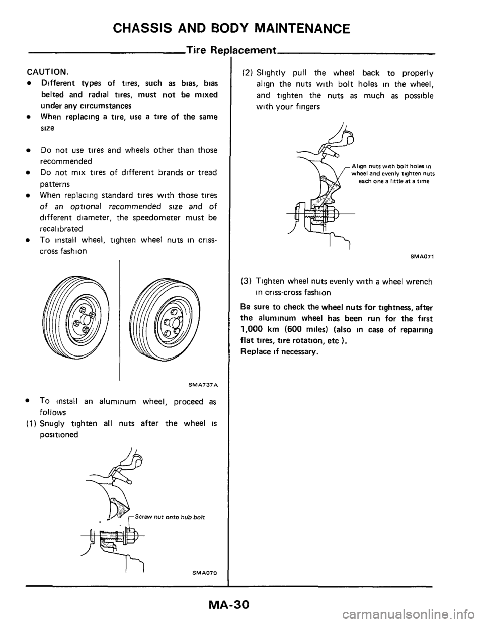
To install wheel, tighten wheel nuts in criss-
cross fashion
SMA737A
To install an aluminum wheel, proceed as
(1) Snugly tighten all nuts after the wheel is
follows
positioned
icement
(2) Slightly pull the wheel back to properly
align the nuts with bolt holes in the wheel,
and tighten the nuts
as much as possible
with
your fingers
Align nuts with bolt haler in wheel and evenly tighten nuts each one a little at a time
SMAOll
(3) Tighten wheel nuts evenly with a wheel wrench
Be sure to check the wheel nuts for tightness, after
the aluminum wheel
has been run for the first
1,000 km (600 miles) (also in case of repairing
flat tires, tire rotation, etc ).
Replace if necessary.
in crtss-cross fashion
MA-30
Page 31 of 38
CHASSIS AND BODY MAINTENANCE
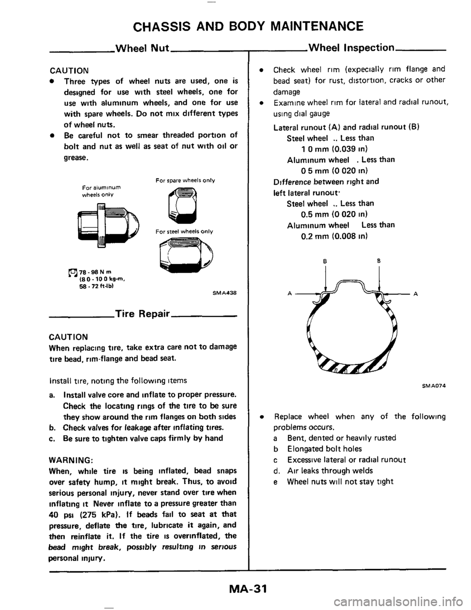
Wheel Nut
CAUTION
0 Three types of wheel nuts are used, one is
designed for use with steel wheels, one for
use with aluminum wheels, and one for use
with spare wheels. Do not mix different types
of wheel nuts.
0 Be careful not to smear threaded portion of
bolt and nut
as well as seat of nut with oil or
grease.
For spare wheels only For aluminum wheels only
For steel wheels only
78 -98 N m 180-100kg-m. 5s 172 ft-lb, SMA438
Tire Repair
CAUTION
When replacing tire, take extra care not to damage
tire bead, rim-flange and bead seat.
Install tire, noting the following items
a. Install valve core and inflate to proper pressure.
Check
the locating rings of the tire to be sure
they show around the rim flanges on both sides
b. Check valves for leakage after inflating tires.
c.
Be sure to tighten valve caps firmly by hand
WARNING:
When, while tire
is being inflated, bead snaps
over safety hump,
it might break. Thus, to avoid
serious personal
injury, never stand over tire when
inflating it Never inflate to a pressure greater than
40 psi (275 kPa). If beads fail to seat at that
pressure, deflate
the tire, lubricate it again, and
then reinflate it. If the tire is overinflated, the
bead might break, possibly resulting
in serious
personal inlury.
Wheel Inspection
Check wheel rim (expecially rim flange and
bead
seat) for rust, distortion, cracks or other
damage Examine wheel rim for
lateral and radial runout,
using dial gauge
Lateral runout (A) and radial runout (B)
Steel wheel .. Less than
Aluminum wheel
. Less than
1 0 mm (0.039 in)
0 5 mm (0 020 in)
Difference between right and
left lateral runout.
Steel wheel .. Less than
Aluminum wheel
Less than
0.5 mm (0 020 in)
0.2 mm (0.008 in)
6 B
Ail..,A
SMA074
Replace wheel when any of the following
problems occurs.
a
b Elongated bolt holes
c
d. Air leaks through welds
e
Bent, dented or heavily rusted
Excessive lateral or radial runout
Wheel nuts
will not stay tight
MA-31
Page 37 of 38
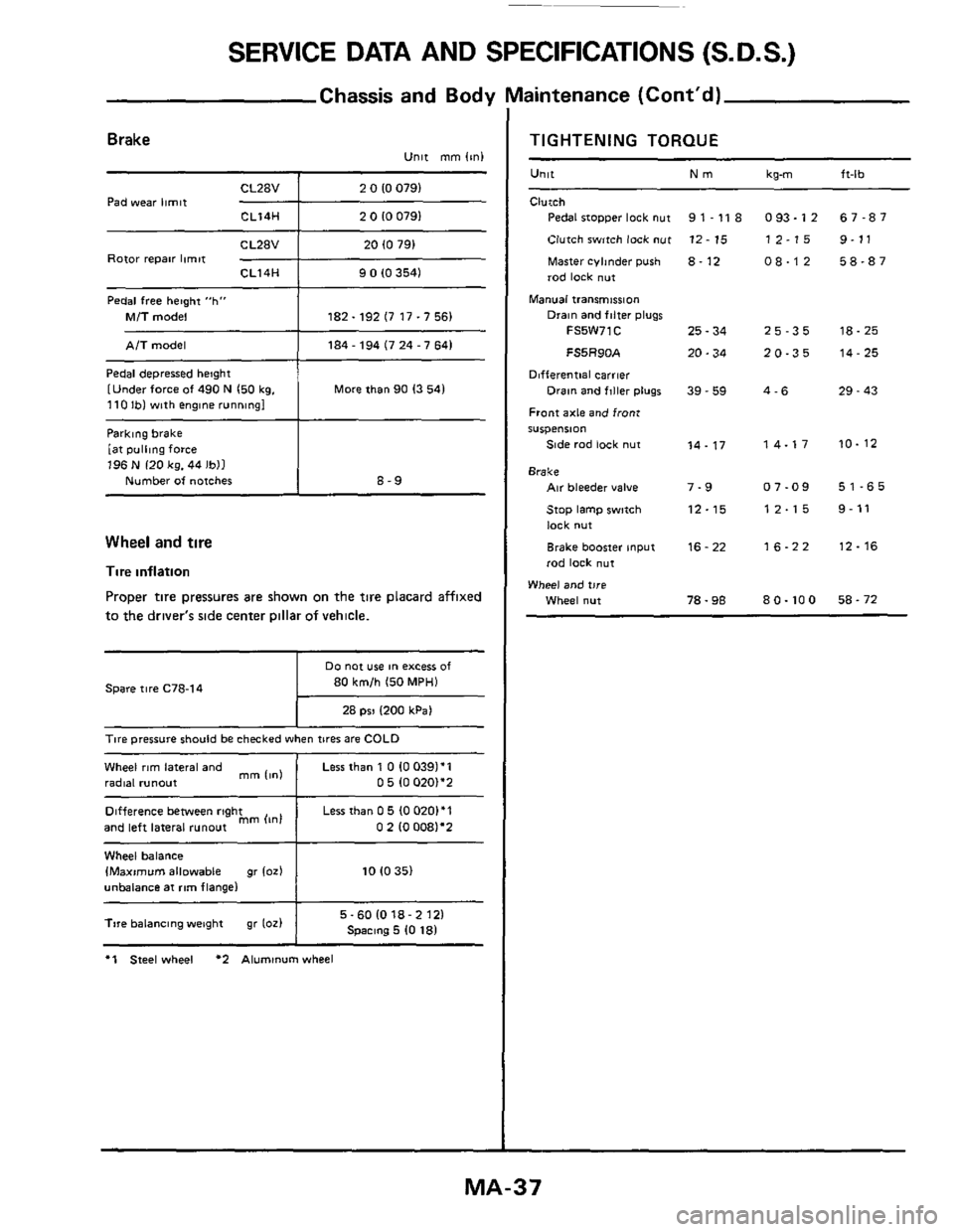
SERVICE DATA AND SPECIFICATIONS (S.D.S.)
Chassis and Body Maintenance (Cont'd)
Parklng brake
[at
pulling force 196 N 120 kg. 44 Ibll
Number of notches
Brake Unit mm (mi
8-9
CL28V 2 0 10 0791
Pad wear limit -+--- CL14H 2 0 10 0791
Difference between right
and left lateral
runout mm (In1
Rotor repair limit CL14H 9 0 (0 3541
Pedal free hetght "h"
Mi7 model 182.192 (7 17.7 56)
Less than 0 5 (0 0201'1
0 2 10 0081'2
Pedal depressed height
[Under force
of 490 N 150 kg. 110 Ibl with englne running1 More than 90 13 541
Wheel and tire
Tire inflation
Proper tire pressures are shown on the tire placard affixed
to the driver's side center Dillar of vehicle.
80 km/h 150 MPH)
28 psi 1200 kPa1
Spare tire C78-14
T~re pressure should be checked when tires are COLD
Wheel rim lateral and
radial runout
1
Less than 1 0 10 0391'1 0 5 (0 020)*2 mm 11nl
Wheel balance IMaximvm allowable gr 102) 10 10 35)
unbalance at rim flange1
I 5-601018-2121 Spmng 5 10 181 Tire balancing weight gr 1oz)
I
*1 Steel wheel *2 Aluminum wheel
TIGHTENING TORQUE
Unit Nm
Clutch
Pedal stopper lock nut
Clutch switch lock
nut
Master cyhnder push 8. 12
rod lock nut
Manual transmission
9 1 - 11 8
12 - 15
Drain and filter plugs
FS5W71C 25 - 34
FS5R90A 20.34
Differential carrier
Front axle and front
S"Spe"Sl0"
Side rad lock nut
Drain and flller plugs 39 - 59
14.17
Brake Air bleeder value 7-9
Stop lamp swmh 12-15
lock nut
Brake booster input
rod lock
nut
16 - 22
Wheel and tire
Wheel nut 78.98
kg-m ft-lb
093.12 67-87
12-15 9-11
08-12 58-87
25-35 18-25
20-35 14-25
4-6 29 - 43
14-17 10-12
07-09 51-65
12-15 9-11
16-22 12-16
80.100 58-72
MA-37