Page 9 of 38

ENGINE MAINTENANCE
Checking Fuel System
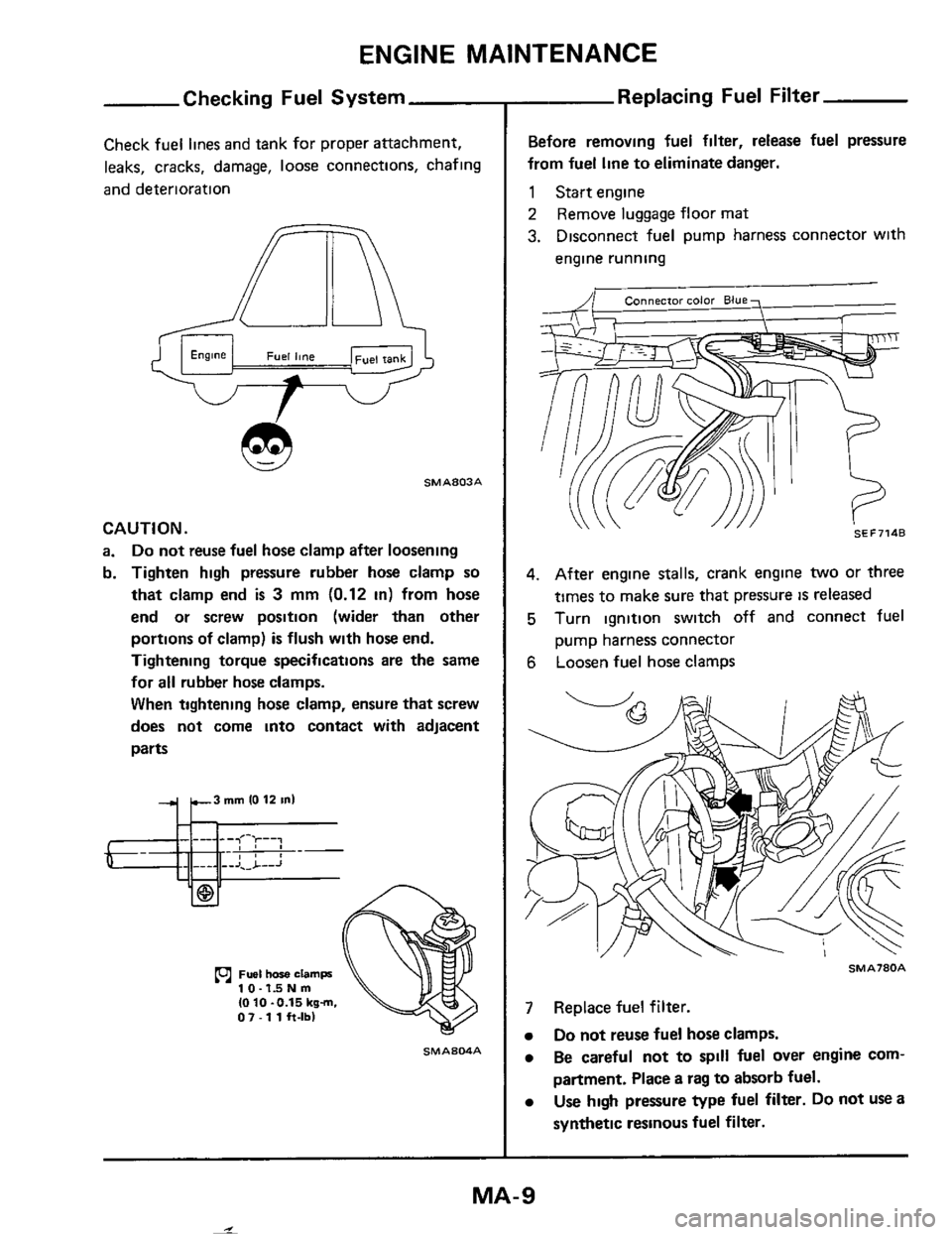
Check fuel lines and tank for proper attachment,
leaks, cracks, damage,
loose connections, chafing
and deterioration
SMA803A
CAUTION.
a. Do not reuse fuel hose clamp after loosening
b. Tighten high pressure rubber hose clamp
so
that clamp end is 3 mm (0.12 in) from hose
end or screw position (wider than other
portions of clamp)
is flush with hose end.
Tightening torque specifications are the same
for all rubber hose clamps.
When tightening hose clamp, ensure that screw
does not come into contact with adjacent
parts
10-1dNm IO 10 -0.15 kgm. 07 - 1 1 h-lbl
SMAS04A
Replacing Fuel Filter
Before removing fuel filter, release fuel pressure
from fuel line
to eliminate danger.
1 Start engine
2 Remove luggage floor mat
3. Disconnect fuel pump harness connector with
engine running
SEF7148
4. After engine stalls, crank engine two or three
times to make sure that pressure
is released
5 Turn ignition switch off and connect fuel
pump harness connector
6 Loosen fuel hose clamps
SMA780A
7 Replace fuel filter.
Do not reuse fuel hose clamps.
Be careful not to spill fuel over engine com-
partment. Place a rag
to absorb fuel.
Use high pressure type fuel filter. Do not use a
synthetic resinous
fuel filter.
MA-9
I
Page 14 of 38
ENGINE MAINTENANCE
Checking idle Speed (VG30E engine)
Preparation
WARNING:
a. Depress brake pedal while accelerating the engine to prevent forward surge of vehicle.
b. Inspection should
be carried out while shift lever IS in "D" position on automatic transmission equipped
models.
c. After inspection and adjustment have been made, shift the lever to "N" or "P" position.
Engage parking brake and lock both front and rear wheels with wheel chocks.
Turn
off air conditioner and headlamps.
Keep front wheels straight ahead.
c START I 1
Start engine and warm up untgl water
temperature Indicator poinrs to middle of
I
To harness 4
Stop engine and anach adapter harness between ignmon coil primary winding terminals and harness connector Then set
timer under no-load, then run engine at
+
Stop engine and connect idle UP solenoid
harness connector
Dismnnm adapter harness Connector and
connect ignition
coil harness connector io
(- END
MA-I 4
-
Page 15 of 38
ENGINE MAINTENANCE
Checking Exhi
48,000 krn (30,000 miles) OR 24 MONTHS
SERVICE
Exhaust gas sensor should be checked after 48,000
km (30,000 miles) or 24 months of operation
After vehicle has been operated for
48,000 km
(30,000 miles), exhaust gas sensor warning lamp
will come on to indicate that sensor should
be
inspected
Digital type
t
After inspection, disconnect warning lamp harness
connector so that warning lamp will not come on
thereafter.
SMA792A
1st Gas Sensor
MA-1 5
.-I
Page 28 of 38
CHASSIS AND BODY MAINTENANCE
Checking Parking Brake
Pull lever with specified amount of force
Check lever stroke and smooth operation
Pullmg force . 196 N I20 kg. 44 Ibl
\' \ \' '
Number of notches 8 -9
SMA436
2 Use adjuster to adjust lever stroke
SMAl35A
3 Bend parking brake warning lamp switch plate
down
so that brake warning light comes on
when ratchet
at parking brake lever IS pulled
one notch and goes out when
fully released
Checking Tire Condition
TIRE CONDITION
0 When tires wear and tread wear indicators
appear, replace them with new ones
Tread wear indicaror Tire iread
WHO24
0 Check tread and side walls for cracks, holes,
separation or damage.
SMAS39A
0 Tire valves for air leakage
TIRE INFLATION
Tire
pressure should be measured when tire is cold.
Tire pressure should be
set to the specifications
on the tire placard located in the vehicle.
Page 37 of 38

SERVICE DATA AND SPECIFICATIONS (S.D.S.)
Chassis and Body Maintenance (Cont'd)
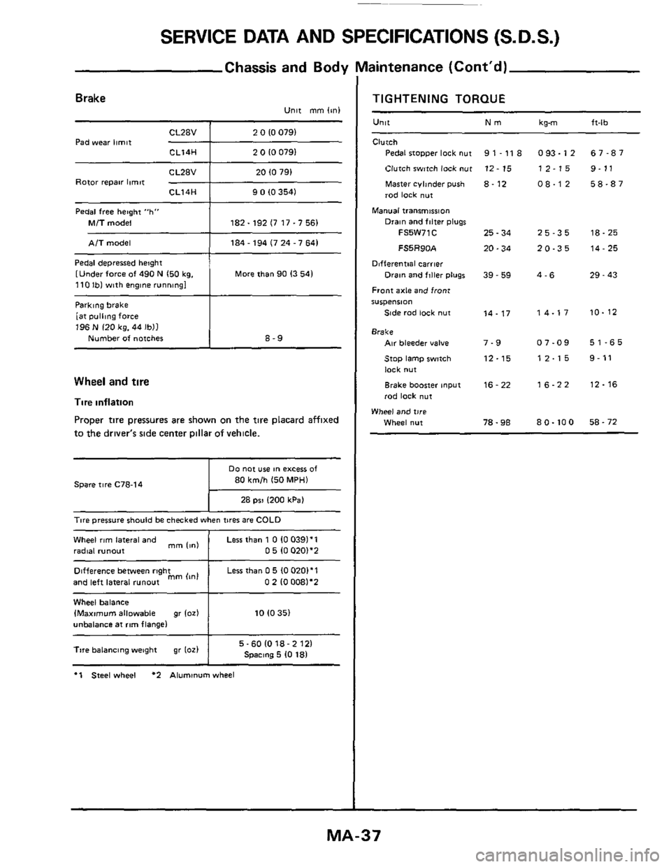
Parklng brake
[at
pulling force 196 N 120 kg. 44 Ibll
Number of notches
Brake Unit mm (mi
8-9
CL28V 2 0 10 0791
Pad wear limit -+--- CL14H 2 0 10 0791
Difference between right
and left lateral
runout mm (In1
Rotor repair limit CL14H 9 0 (0 3541
Pedal free hetght "h"
Mi7 model 182.192 (7 17.7 56)
Less than 0 5 (0 0201'1
0 2 10 0081'2
Pedal depressed height
[Under force
of 490 N 150 kg. 110 Ibl with englne running1 More than 90 13 541
Wheel and tire
Tire inflation
Proper tire pressures are shown on the tire placard affixed
to the driver's side center Dillar of vehicle.
80 km/h 150 MPH)
28 psi 1200 kPa1
Spare tire C78-14
T~re pressure should be checked when tires are COLD
Wheel rim lateral and
radial runout
1
Less than 1 0 10 0391'1 0 5 (0 020)*2 mm 11nl
Wheel balance IMaximvm allowable gr 102) 10 10 35)
unbalance at rim flange1
I 5-601018-2121 Spmng 5 10 181 Tire balancing weight gr 1oz)
I
*1 Steel wheel *2 Aluminum wheel
TIGHTENING TORQUE
Unit Nm
Clutch
Pedal stopper lock nut
Clutch switch lock
nut
Master cyhnder push 8. 12
rod lock nut
Manual transmission
9 1 - 11 8
12 - 15
Drain and filter plugs
FS5W71C 25 - 34
FS5R90A 20.34
Differential carrier
Front axle and front
S"Spe"Sl0"
Side rad lock nut
Drain and flller plugs 39 - 59
14.17
Brake Air bleeder value 7-9
Stop lamp swmh 12-15
lock nut
Brake booster input
rod lock
nut
16 - 22
Wheel and tire
Wheel nut 78.98
kg-m ft-lb
093.12 67-87
12-15 9-11
08-12 58-87
25-35 18-25
20-35 14-25
4-6 29 - 43
14-17 10-12
07-09 51-65
12-15 9-11
16-22 12-16
80.100 58-72
MA-37