Page 25 of 38
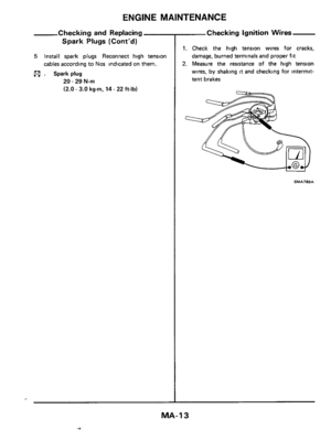
CHASSIS AND BODY MAINTENANCE
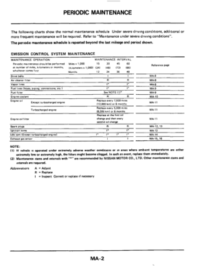
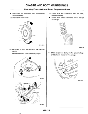
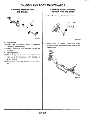
Checking Rear
PRELIMINARY INSPECTION
0 Tire pressure.
0 Wheel bearing axial play
0 Shock absorber operation.
0
0 Measure vehicle height (Unladen)
Tighten each rear axle and suspension part
The vehicle must be on a level surface both
fore and
aft, and laterally
Repair or replace the damaged portion or parts
0
"Unladen"
Fuel tank, radiator and engine oil tank all full
Spare
tire, jack, hand tools, mats in position
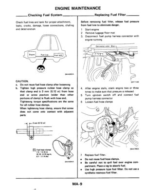
CAMBER
Camber
is preset at factory and cannot be adjusted
Camber:
-1"55'tO -25'
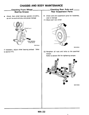
TOE-IN
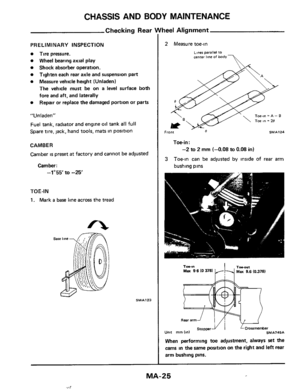
1. Mark a base line across the tread
SMA123
nee1 Alignment
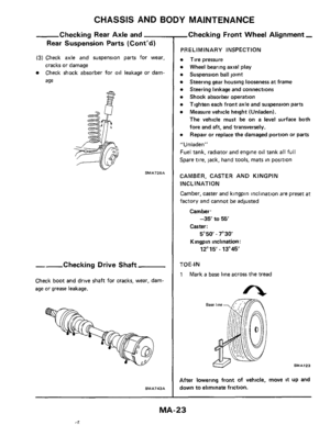
2 Measure toe-in
~~ner parallel to center Ime of body-
Toe-in = A - B
, Front 8 SMA124
Toe-in:
-2 to 2 mm (-0.08 to 0.08 in)
3 Toein can be adjusted by inside of rear arm
bushing pins
Unit
Tobl" TObOltl Max 9 6 10 3781 Max 9.6 (0.378)
When performing toe adjustment, always set the
cams in the same position on the right and left rear
arm bushing pins.
MA-25
,,_l
Page 26 of 38
CHASSIS AND BODY MAINTENANCE
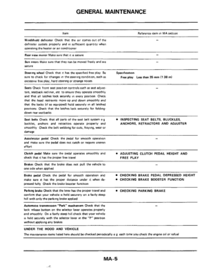
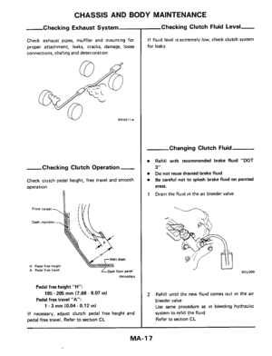
-Checking Brake Fluid Level
and Leaks
If fluid level is extremely low, check brake system
for leaks
Changing Brake Fluid
0 Refill with recommended brake fluid "DOT
3".
Do not reuse drained brake fluid.
Be careful not to splash brake fluid on painted
areas.
Drain brake fluid in each
air bleeder valve. 1
SMA26IA
2 Refill until new brake fluid comes out of each
air bleeder valve
Use same procedure as in bleeding hydraulic
system to refill
brake fluid
Refer to section
BR
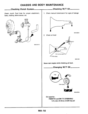
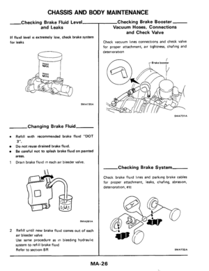
Checking Brake Booster
Vacuum Hoses, Connections
and Check Valve
Check vacuum lines connections and check valve
for proper attachment,
air tightness, chafing and
deterioration
I rBrake booster
Checking Brake System
Check brake fluid lines and parking brake cables
for proper attachment, leaks, chafing, abrasion,
deterioration, etc
\v
SMA732A
MA-26
Page 27 of 38
CHASSIS AND BODY MAINTENANCE
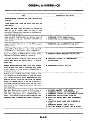
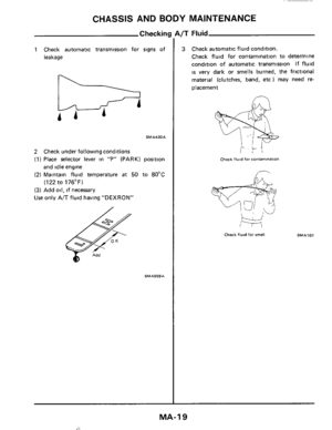
Checking Disc Brake
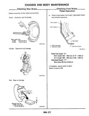
Check condltlon of disc brake components
Rotor Condition and thickness
Caliper Operation and leakage
Pad Wear or damage
SMA733A
SMA?34A
A
Checking Foot Brake
Pedal Operation
0 Check brake pedal free height, depressed height
and smooth operation
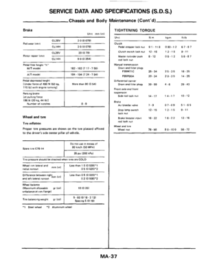
h Pedal free height H Depressed height Dash floor panel
Pedal free height "h":
M/T model 182 - 192 mm (7.17 - 7.56 in)
AlT model 184 - 194 mm (7.24 - 7.64 in)
More than 90 mm (3.54 in)
Depressed height "H":
If necessary, adjust pedal heights
Refer to section
BR
MA- 2 7
Page 28 of 38
CHASSIS AND BODY MAINTENANCE
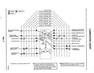
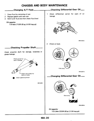
Checking Parking Brake
Pull lever with specified amount of force
Check lever stroke and smooth operation
Pullmg force . 196 N I20 kg. 44 Ibl
\' \ \' '
Number of notches 8 -9
SMA436
2 Use adjuster to adjust lever stroke
SMAl35A
3 Bend parking brake warning lamp switch plate
down
so that brake warning light comes on
when ratchet
at parking brake lever IS pulled
one notch and goes out when
fully released
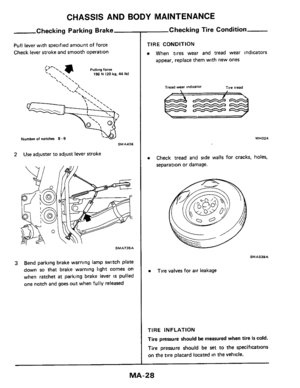
Checking Tire Condition
TIRE CONDITION
0 When tires wear and tread wear indicators
appear, replace them with new ones
Tread wear indicaror Tire iread
WHO24
0 Check tread and side walls for cracks, holes,
separation or damage.
SMAS39A
0 Tire valves for air leakage
TIRE INFLATION
Tire
pressure should be measured when tire is cold.
Tire pressure should be
set to the specifications
on the tire placard located in the vehicle.
Page 29 of 38
-
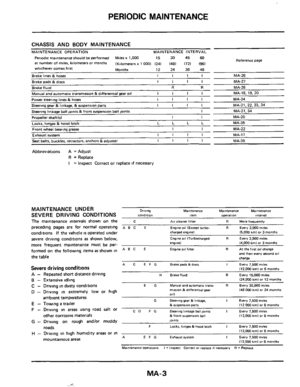
Abnormal tire wear
Correct abnormal tire wear according to the chart
shown below
Condition
Shoulder wear
Center wear
Feathere")
CHASSIS AND BODY MAINTENANCE
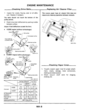
,Checking Tire Condition (Cont'd)-
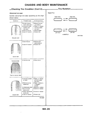
Abnormal tire wear
Correct abnormal tire wear according to the chart
shown below
Condition
Shoulder wear
Center wear
Feathered edge
Toe-in or toe out wea
Uneven Wear
Probable cause
Underinflation
lboth sides wear) Incorrect wheel
camber lone side wear1 Hard cornering
Lack of rotation
. Overlnflatlon
Lack of rotation
.Incorrect toe
rn Incorrect camber or carter
Malfunctioning rurpenrm
v Unbalanced wheel v Our of round
brake drum
Other mechantcal conditions Lack Of rotation
Corrective actton
Measure and ad-
just pressure . Repar. or replace
axle and rurpen- IlO" parts
.Reduce speed . Rotate tires
Measure and
Rotate tires
adlust pressure
*Adlust toe In
Repa~r. or replace axle and iuwm
SlO" parts
If necessary.
rel"6tall
Repar replace or,
m Balance or replace Correct or replace
m Correct or replace
v Rotate tires
SMA068
Tire Rotation
Radial Tire
Right front Right rear
a=-
-== Left rear
Left front
4 WHEELS SMA73SA
MA-29
Page 30 of 38

CHASSIS AND BODY MAINTENANCE
Tire Rei
CAUTION.
Different types of tires, such as bias, bias
belted and radial
tires, must not be mixed
under any circumstances
When replacing
a tire, use a tire of the same
size
Do not use tires and wheels other than those
recommended
Do not mix tires of different brands or tread
patterns
When replacing standard
tires with those tires
of an oprional recommended size and of
different diameter, the speedometer must be
recalibrated
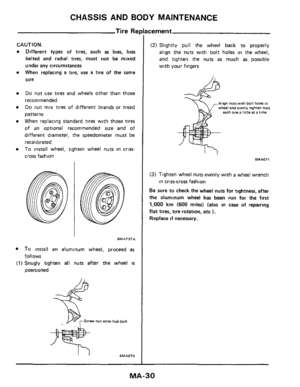
To install wheel, tighten wheel nuts in criss-
cross fashion
SMA737A
To install an aluminum wheel, proceed as
(1) Snugly tighten all nuts after the wheel is
follows
positioned
icement
(2) Slightly pull the wheel back to properly
align the nuts with bolt holes in the wheel,
and tighten the nuts
as much as possible
with
your fingers
Align nuts with bolt haler in wheel and evenly tighten nuts each one a little at a time
SMAOll
(3) Tighten wheel nuts evenly with a wheel wrench
Be sure to check the wheel nuts for tightness, after
the aluminum wheel
has been run for the first
1,000 km (600 miles) (also in case of repairing
flat tires, tire rotation, etc ).
Replace if necessary.
in crtss-cross fashion
MA-30
Page 31 of 38

CHASSIS AND BODY MAINTENANCE
Wheel Nut
CAUTION
0 Three types of wheel nuts are used, one is
designed for use with steel wheels, one for
use with aluminum wheels, and one for use
with spare wheels. Do not mix different types
of wheel nuts.
0 Be careful not to smear threaded portion of
bolt and nut
as well as seat of nut with oil or
grease.
For spare wheels only For aluminum wheels only
For steel wheels only
78 -98 N m 180-100kg-m. 5s 172 ft-lb, SMA438
Tire Repair
CAUTION
When replacing tire, take extra care not to damage
tire bead, rim-flange and bead seat.
Install tire, noting the following items
a. Install valve core and inflate to proper pressure.
Check
the locating rings of the tire to be sure
they show around the rim flanges on both sides
b. Check valves for leakage after inflating tires.
c.
Be sure to tighten valve caps firmly by hand
WARNING:
When, while tire
is being inflated, bead snaps
over safety hump,
it might break. Thus, to avoid
serious personal
injury, never stand over tire when
inflating it Never inflate to a pressure greater than
40 psi (275 kPa). If beads fail to seat at that
pressure, deflate
the tire, lubricate it again, and
then reinflate it. If the tire is overinflated, the
bead might break, possibly resulting
in serious
personal inlury.
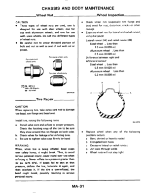
Wheel Inspection
Check wheel rim (expecially rim flange and
bead
seat) for rust, distortion, cracks or other
damage Examine wheel rim for
lateral and radial runout,
using dial gauge
Lateral runout (A) and radial runout (B)
Steel wheel .. Less than
Aluminum wheel
. Less than
1 0 mm (0.039 in)
0 5 mm (0 020 in)
Difference between right and
left lateral runout.
Steel wheel .. Less than
Aluminum wheel
Less than
0.5 mm (0 020 in)
0.2 mm (0.008 in)
6 B
Ail..,A
SMA074
Replace wheel when any of the following
problems occurs.
a
b Elongated bolt holes
c
d. Air leaks through welds
e
Bent, dented or heavily rusted
Excessive lateral or radial runout
Wheel nuts
will not stay tight
MA-31
Page 32 of 38

CHASSIS AND BODY MAINTENANCE
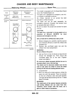
Balancing Wheels
Cause
Symptom
of unbalanci
correct,vt
action
Wheel static
unbalance
Wheel tramp
Wheel shimmy
lalance statically
Place balance weights here
L0CatlO"J
Wheel dynamic
unbalance
Wheel shimmy
Balance dynamically
Wheel shimmy
n
Heavy locatnoni
u
Wheel shimmy
SMAO7S
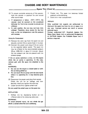
Spare Tire
This model is equipped with the Space Saver Spare
tire or the Foldable Spare tire
The spare tire
is designed for emergency use only
It
IS stored in a deflated condition
An inflator (canister or air pump) has been
provided to inflate the spare
The spare tire can be used repeatedly for
emergency situations However, the canister must
be replaced after each inflation
Be sure to obtain the proper size canister for spare
tire
size
CAUTION:
The spare tire
is restricted in driving speed up to a
maximum
of 80km/h (50MPH) for short
distances and emergency use only.
INFLATION WITH APPROVED INFLATOR
1 Before changing tire, carefully read the caution
and directions affixed on both the inflator and
the spare tire
2 Remove the uninflated spare tire and the
inflator from rear compartment
WARNING. Do not inflate at
this point.
3 Jack up front or rear of vehicle as required and
remove the damaged
tire Then mount the
uninflated spare
tire to the axle (Tighten
wheel nuts slightly
)
On aluminum wheels equipped vehicles be sure to
use spare wheel nuts in the tool bag
The wheel nuts for aluminum wheels must not be
used on the spare tire wheel to avoid the wheel
coming off the axle and causing personal injury.
4 Using Canister
(1) With tire valve at 6 o'clock position. inflate the
spare tire with the canister Place tire canister
on the
tire inflaction valve and push squarely
until
gas can be heard entering the tire It takes
about
3 minutes
WARNING:
The metal parts of the canister become extremely
cold during inflation and can cause frost bite.
Therefore, avoid contact with the metal, use a
glove or other means
of protection.
MA-32

Tighten ea")


