Page 28 of 38
CHASSIS AND BODY MAINTENANCE
Checking Parking Brake
Pull lever with specified amount of force
Check lever stroke and smooth operation
Pullmg force . 196 N I20 kg. 44 Ibl
\' \ \' '
Number of notches 8 -9
SMA436
2 Use adjuster to adjust lever stroke
SMAl35A
3 Bend parking brake warning lamp switch plate
down
so that brake warning light comes on
when ratchet
at parking brake lever IS pulled
one notch and goes out when
fully released
Checking Tire Condition
TIRE CONDITION
0 When tires wear and tread wear indicators
appear, replace them with new ones
Tread wear indicaror Tire iread
WHO24
0 Check tread and side walls for cracks, holes,
separation or damage.
SMAS39A
0 Tire valves for air leakage
TIRE INFLATION
Tire
pressure should be measured when tire is cold.
Tire pressure should be
set to the specifications
on the tire placard located in the vehicle.
Page 29 of 38

CHASSIS AND BODY MAINTENANCE
,Checking Tire Condition (Cont'd)-
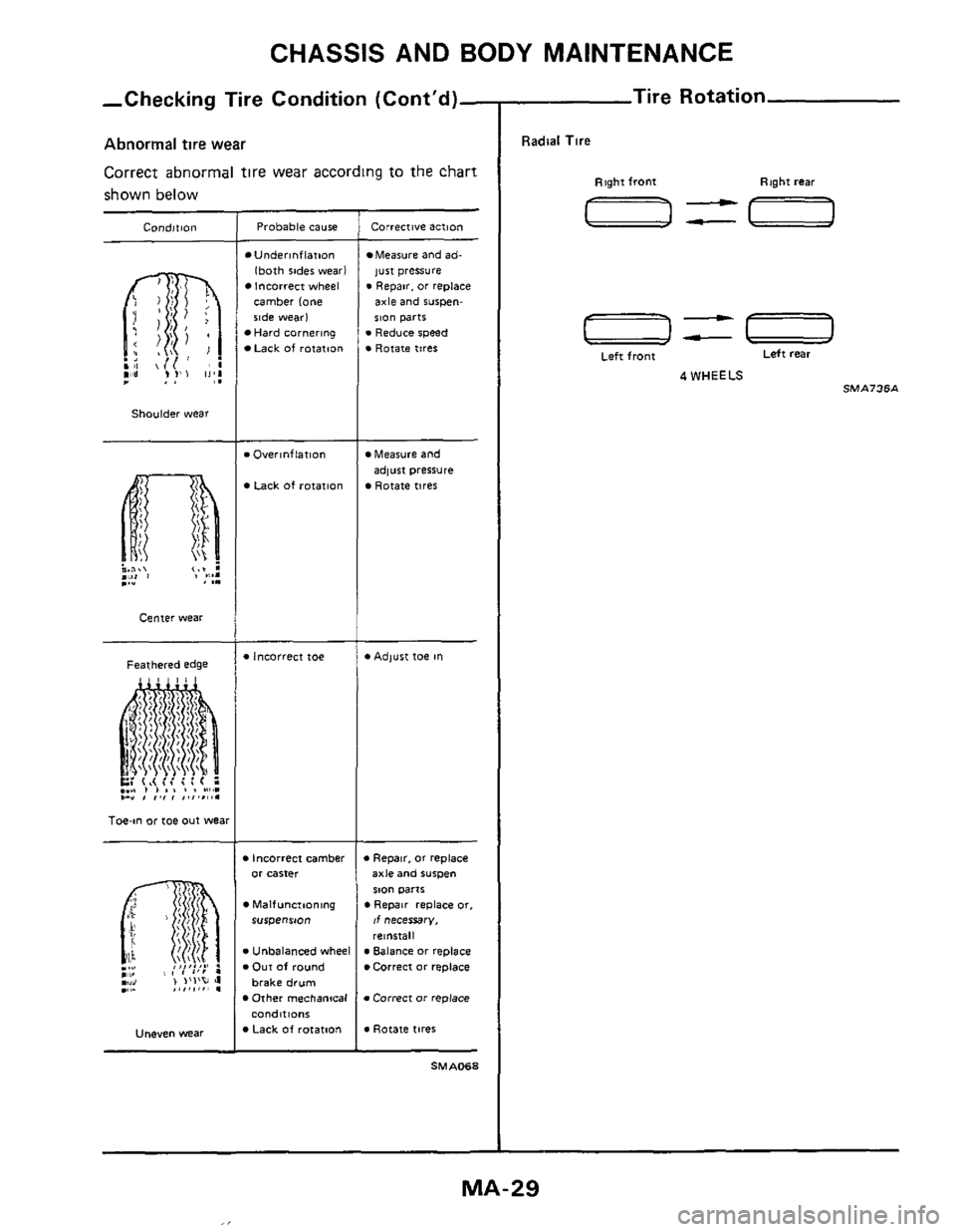
Abnormal tire wear
Correct abnormal tire wear according to the chart
shown below
Condition
Shoulder wear
Center wear
Feathered edge
Toe-in or toe out wea
Uneven Wear
Probable cause
Underinflation
lboth sides wear) Incorrect wheel
camber lone side wear1 Hard cornering
Lack of rotation
. Overlnflatlon
Lack of rotation
.Incorrect toe
rn Incorrect camber or carter
Malfunctioning rurpenrm
v Unbalanced wheel v Our of round
brake drum
Other mechantcal conditions Lack Of rotation
Corrective actton
Measure and ad-
just pressure . Repar. or replace
axle and rurpen- IlO" parts
.Reduce speed . Rotate tires
Measure and
Rotate tires
adlust pressure
*Adlust toe In
Repa~r. or replace axle and iuwm
SlO" parts
If necessary.
rel"6tall
Repar replace or,
m Balance or replace Correct or replace
m Correct or replace
v Rotate tires
SMA068
Tire Rotation
Radial Tire
Right front Right rear
a=-
-== Left rear
Left front
4 WHEELS SMA73SA
MA-29
Page 33 of 38

CHASSIS AND BODY MAINTENANCE
Spare Til
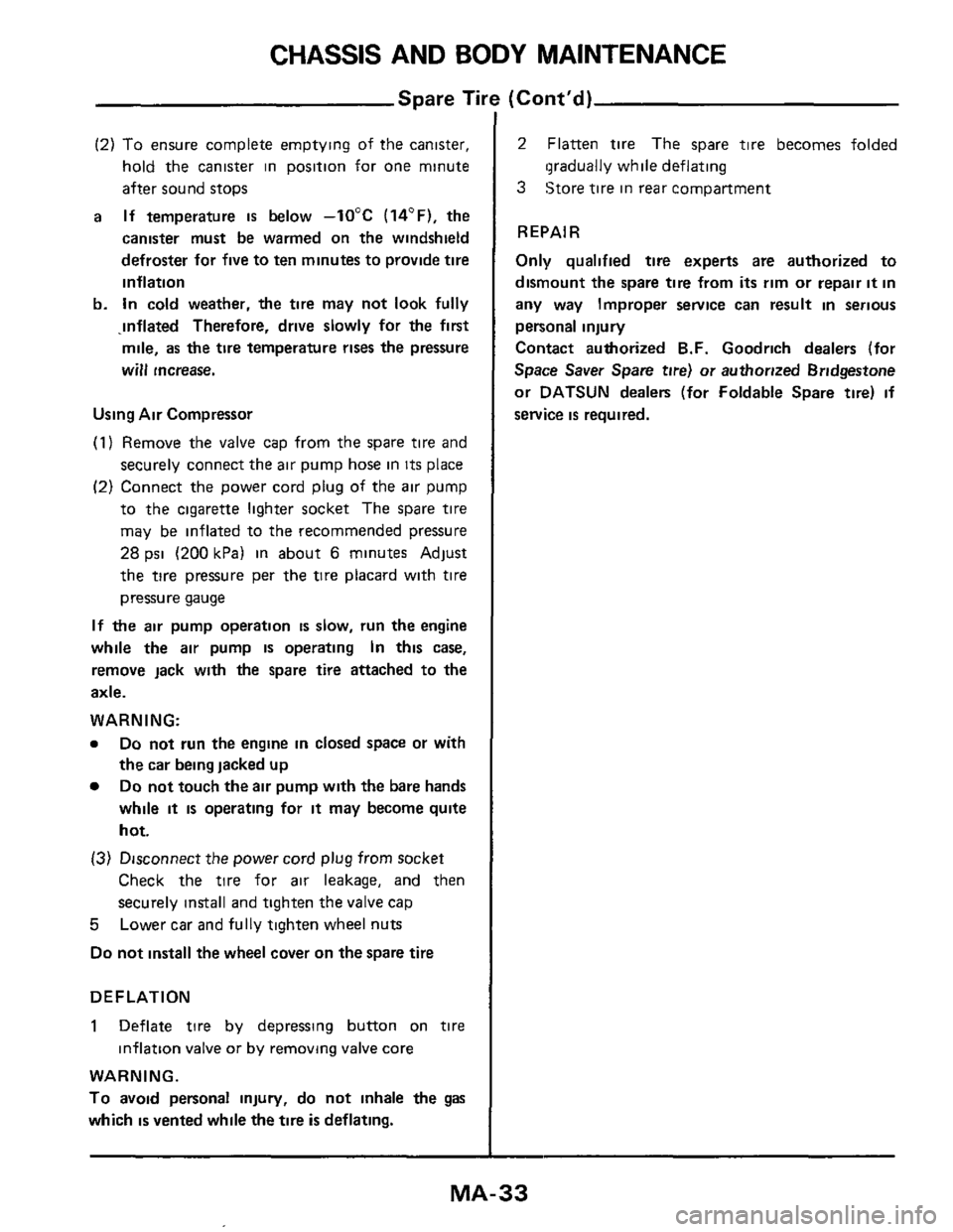
(2) To ensure complete emptying of the canister,
hold the canister in position for one minute
after sound stops
If temperature is below -10°C (14OF), the
canister must be warmed on
the windshield
defroster for five to ten minutes to provide
tire
inflation
b. In cold weather, the tire may not look fully
.inflated Therefore, drive slowly for the
first
mile, as the tire temperature rises the pressure
will mcrease.
a
Using Air Compressor
(1) Remove the valve cap from the spare tire and
securely connect the air pump hose in
its place
(2) Connect the power cord plug of the air pump
to the cigarette lighter socket The spare
tire
may be inflated to the recommended pressure
28 psi (200 kPa) in about 6 minutes Adjust
the
tire pressure per the tire placard with tire
pressure gauge
If the air pump operation is slow, run the engine
while the air pump is operating In this case,
remove jack with
the spare tire attached to the
axle.
WARNING:
0
0
Do not run the engine in closed space or with
the car being jacked up
Do not touch the air pump with the bare hands
while
it is operating for it may become quite
hot.
(3) Disconnect the power cord plug from socket
Check the
tire for air leakage, and then
securely install and tighten the valve cap
5 Lower car and fully tighten wheel nuts
Do not
install the wheel cover on the spare tire
DEFLATION
1 Deflate tire by depressing button on tire
inflation valve or by removing valve core
WARN1 NG.
To avoid personal injury, do not inhale the
gas
which is vented while the tire is deflating.
(Cont'd)
2 Flatten tire The spare tire becomes folded
3
REPAIR
Only qualified tire experts are authorized to
dismount the spare tire from
its rim or repair it in
any way Improper service can result
in serious
personal injury
Contact aumorized B.F. Goodrich dealers (for
Space Saver Spare tire)
or authorized Bridgestone
or DATSUN dealers (for Foldable Spare tire)
if
setvice is required.
iqradually while deflating
Store tire in rear compartment
MA-33
Page 37 of 38

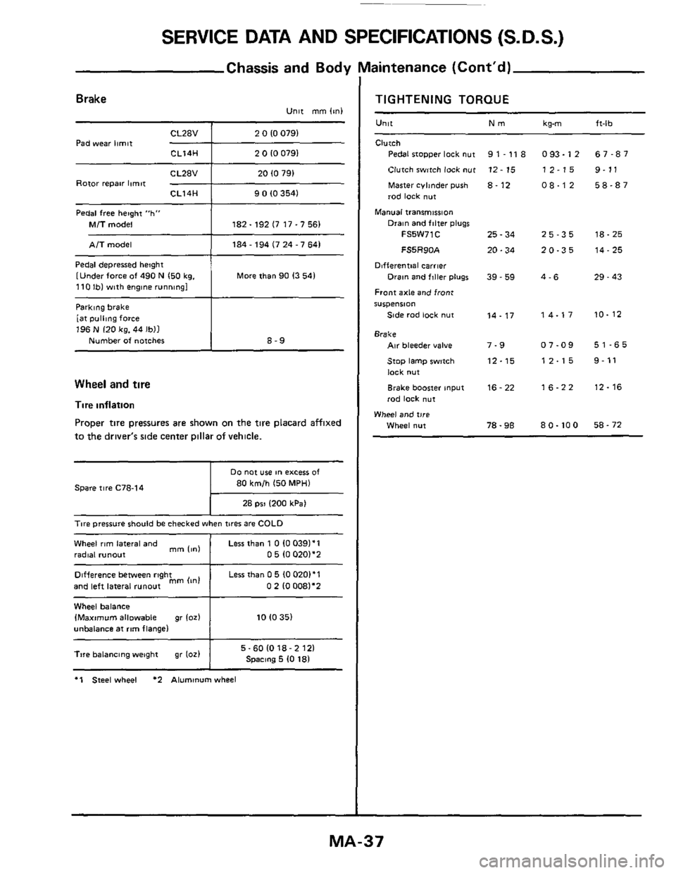
SERVICE DATA AND SPECIFICATIONS (S.D.S.)
Chassis and Body Maintenance (Cont'd)
Parklng brake
[at
pulling force 196 N 120 kg. 44 Ibll
Number of notches
Brake Unit mm (mi
8-9
CL28V 2 0 10 0791
Pad wear limit -+--- CL14H 2 0 10 0791
Difference between right
and left lateral
runout mm (In1
Rotor repair limit CL14H 9 0 (0 3541
Pedal free hetght "h"
Mi7 model 182.192 (7 17.7 56)
Less than 0 5 (0 0201'1
0 2 10 0081'2
Pedal depressed height
[Under force
of 490 N 150 kg. 110 Ibl with englne running1 More than 90 13 541
Wheel and tire
Tire inflation
Proper tire pressures are shown on the tire placard affixed
to the driver's side center Dillar of vehicle.
80 km/h 150 MPH)
28 psi 1200 kPa1
Spare tire C78-14
T~re pressure should be checked when tires are COLD
Wheel rim lateral and
radial runout
1
Less than 1 0 10 0391'1 0 5 (0 020)*2 mm 11nl
Wheel balance IMaximvm allowable gr 102) 10 10 35)
unbalance at rim flange1
I 5-601018-2121 Spmng 5 10 181 Tire balancing weight gr 1oz)
I
*1 Steel wheel *2 Aluminum wheel
TIGHTENING TORQUE
Unit Nm
Clutch
Pedal stopper lock nut
Clutch switch lock
nut
Master cyhnder push 8. 12
rod lock nut
Manual transmission
9 1 - 11 8
12 - 15
Drain and filter plugs
FS5W71C 25 - 34
FS5R90A 20.34
Differential carrier
Front axle and front
S"Spe"Sl0"
Side rad lock nut
Drain and flller plugs 39 - 59
14.17
Brake Air bleeder value 7-9
Stop lamp swmh 12-15
lock nut
Brake booster input
rod lock
nut
16 - 22
Wheel and tire
Wheel nut 78.98
kg-m ft-lb
093.12 67-87
12-15 9-11
08-12 58-87
25-35 18-25
20-35 14-25
4-6 29 - 43
14-17 10-12
07-09 51-65
12-15 9-11
16-22 12-16
80.100 58-72
MA-37