Page 57 of 105
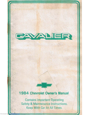
TIE-DOWNS
The crossrails will adjust to help position your load. Rotate the large k")
Downloaded from www.Manualslib.com manuals search engine OJ ROOF RAIL ASM.
ill CROSSRAI LS
mCRO~RAIL KNOBS
[!)TIE-DOWNS
The crossrails will adjust to help position your load. Rotate the large knob ("No.3" in the illustration) counterclockwise to move or remove . the crossrails ;
and clockwise to lighten down or install the crossrails .
Attached to the top
of the crossrails are two adjustable tie-downs ('·No. 4" in
the illustration). There is also one adjustable tie-down located in the center of
each outer roof
slat assembly (also called "No.4" in the illustration). The tiedowns may be easily moved within the outer slat assembly and across the top
of the crossrails to the desired position. To move the tie-down, rotate il
counterclockwise to loosen and clockwise to tight'lfl.95>wn. If needed 'to secure
a certain type of load, the tie-downs on the crossrails may be rerncved and
repositioned on the outer roof slat assemblies.
While under way, check, now and then to make sure, the crossrails, tle~
downs, and cargo are securely fastened, to help prevent damage or loss.
See your Chevrolet dealer for attachments to your Chevrolet luggage carrier to
hold bicycles, skis and other items, and for straps to help secure your cargo ,
which are available as accessories .
CAUTION: The cr0SSt8ils may be removed 'rom the root luggage carrier. Never carry the crour,ils loose or unseCured in the passenger area because they cookr be thrown
about and injure people during .. collision or a sudden maneuver. ee sure to stow t~ crossralla in the vinyl bag. Place the bag on the rea, load floor behind the second seat and secure the straps (on the bag) to the anchor brackets as ahown. The bag, and
brackets are designed to secure ONLY the crossrails.
2-41
Page 58 of 105
Downloaded from www.Manualslib.com manuals search engine 2-42
Page 59 of 105

Downloaded from www.Manualslib.com manuals search engine •
~-
SECTION 3
IN CASE OF EMERGENCY
. FOUR·WAY HAZARD WARNING FLASHER
Use the hazard warning flasher to warn other drivers any time your vehicle becomes a traffic hazard. day or night. Avoid stopping on the roadway if possible, To turn it on. push the button (inside the collar) beneath the steering
wheelan the right of the steering column. The flasher should work with the
ignition either off or on .
The turn
signals do not work when the hazard flasher is on. On some vehicles. if the brake pedal is pushed down. the lights will not flash until the brake is
released. To turn off the flasher. pull the button collar out.
EMERGENCY STARTING YOUR VEHICI.E .DUE TO A
DISCHARGED BATTERY
H your vehicle will not start rue to a discharged battery. it can often be started
by using energy from another battery -a procedure called "jump starting."
NOnCE: Do not push or tow thl' vehicle to start It. Under some conditions this may damage the catalytlc ·converter or other parts of the vehicle. Alao, 'since this vehicle ,has a 12 volt bettery, be sure the vehlc .. or equiprnetlt used to jump start your engine Is also 12 volt. Use of any other type syltem mey damage the vehicle', electrical components.
Jump Starting Instructions
CAUTION: Battet1H productl .~ gases, contain corrosive acid and supply ~ls of electrical current hlgh enough &0 cause bums. Therefore, to reduce the risk of peraoMIlnjury when working near 8 banery:
• Always shield your ayes and avOid leaning over a MtttIry whenever possible.
• Do not expose a battery to open,'ftames or spark&.
• Be sure any batter. that have fll .... caps are properly filled with fluid.
• Do not _aDow battery acid to contact eyes or skin. Flush any contacted area with w8ter Immediately and thOrOughly. Mel get mecIcaI hMp.
• FoUow each -step in the jump at8rting Jnstructiona.
3-1
Page 60 of 105
 battery so that the booster Qumper) cables will reach but never let the vehicles touch.")
Downloaded from www.Manualslib.com manuals search engine 1. Position the vehicle with the good (charged) battery so that the booster Qumper) cables will reach but never let the vehicles touch. Also, be sure
booster cables to be used do not have loose or missing insulation.
2. tn both vehicles :
• Turn off ignition and all lights and accessories except the hazard
flasher or any lights needed for lhe work area.
• Apply the parking brake firmly, and shift the automatic transaxle or transmission to Park (or manual transaxle or transmission to neutral).
3. Making sure the cable clamps do not touch any other metal parts, clamp
one end of the first booster cable to the positive " +" (red) terminal on
one battery, and the other end to the positive terminal on the other battery .
Never connect"
+ " (red) to "- " (black).
Make Connections in Numerical Order
First Jump.r C.bl.
Do NOT Allow
Vehicle. to Touchl Discharged
Battery
S.cond Jump.r C.bl.
Make Last
onnectlon on
Engine,
Away
from Battery
Battery in Vehicle
with Charged Battery L-'= ___
o
4. Clamp one end of the second cable to the negative" -" (black) terminal
of the
good (charged) battery and make the final connection to a heavy metal bracket on the engine about 450 millimeters (18 inches) from the
discharged battery.
DO NOT use the Delcotron (generator) mounting
bracket attaching nut or bolt or, the bolt on the rear of the Delcotron as
the final ground attachment. Such improper grounding could cause
damage to the Delcotron . Either of the two bolts atop the mounting
bracket ,
or the air conditioner compressor (if so equipped) generally make a good point for the final ground attachment. See the illustration. Make
sure
the cables are not on or near pulleys , fans , or other parts that will move when the engine is started.
5. Start the engine of the vehicle with the good (charged) battery and run the
engine at a moderate speed for several minutes. Then, start the engine of
the vehicle that has the discharged battery.
6. Remove the booster cables by. raversing the above installation sequence
exactly. While removing each clamp, take care it does not touch any other metal while the other end remains attached. .
3-2
•
Page 61 of 105

Downloaded from www.Manualslib.com manuals search engine ENGINE COOLING SYSTEM OVERHEATING
If you see or hear escaping steam or have other reason to suspect there is a
serious overheat condition, stop and park the vehicle as soon as it is safe
to do so and turn off the engine immediately and get out of the vehicle.
The cooling system may overheat if the coolant level is too low, if there is a
sudden
loss of coolant (such as a worn hose splitting), or if other problems occur. It may also temporarily overheat during severe operating conditions
such as:
• climbing a long hill on a hot day,
• stopping after high-speed driving,
• idling for long periods in trallic, or
• towing a trailer.
I! the Engine Coolant Temperature light comes on (or if you have an Engine
Coolant Temperature gage and it shows an overheat condition), or you have
any reason to suspect the engine may be overheating:
• tfyour air conditioner is on, turn it off.
• If you are stopped in traffic, shift the transaxle to "N" (Neutral).
If the warning light does not go off (or engine coolant temperature does not
start to drop) within a minute
Or two:
• Pull over, stop and park the vehicle as soon as it is safe to do so.
• Let the engine run at normal idle speed for two or three minutes.
I! the warning light does not go off (or engine coolant temperature does not
start to drop),
turn off the engine and get out of the car, then proceed as
follows:
CAUTION: To help avokt being burned:
• DO NOT OPEN ntE HOOD if you see or hear steam or coolant escaping from the engine compartment. Wait until no steam or coolant can be seen or heard before opening the hood.
• DO NOT REMOVE THE RADIATOR CAP or coolant RECOVERY TANK CAP IF THE COOLANT IN THE RECOVERY TANK IS BOIUNG. Also do not remove the radiator
cap while the engine and radiator are still hot Scalding fluid and steam can be blown out under pressure if eHher cap is taken off too soon.
I! no steam or coolant can be seen or heard, raise the engine hood. If the
coolant is boiling, wait until it stops before proceeding. Look at the
3-3
Page 62 of 105

Downloaded from www.Manualslib.com manuals search engine coolant level in the see-through recovery tank. The coolant level should be at
or above the
"FULL HOT" mark on the recovery tank.
CAUTION: Keep hand., toots and clothing -away from the engine COOling fa", to help prevent personIl intUry. lhiIlan is electric and can come on whether Or not the engine Is rUnning. 111. tan can start automatically In .respon .. to a heat sensor when the ignition Is in "Run."
Make sure the water pu"",, belts are not broken, or off the pulleys , and that the fan runs when the engine is running and there is an indication on the instrument panel of an overheat condition.
If the coolant level in the recovery tank is low, look for leaks at the radiator
hoses and connections, heater hoses and connections, radiator I and water pump. If you find major leaks, or spot other problems that may have caused
the engine to overheat,
do not run the engine untilthese problems have been
corrected. If you do not find a leak or other problem, caretully add coolant to
the recovery tank. (Coolant is a mixture of ethylene glycol antifreeze and water; see "Engine Cooling System" in "'Service and Maintenance," Section 5, for the proper antifreeze and mixture.) .
CAUTION: Under: some:' conditione, the ethylen~ glycol In engine coolant Is . combustible. -To help avoid being burned, DO NOT spill antifreeze or coolant on the exhauat system or hot engine parts..
If the coolant level in the recovery tank is at the correct level but there is still
an indication on the instrument panel of an overheat condition:
•
You may add coolant directly to the radiator. YOU MUST LET ENGINE COOL FIRST. See "Coolant Replacement" under "Engine Cooling
System"
in Section 5, "Service and Maintenance" in this manual. Follow steps t through 3 for the correct way to remove the radiator
cap
and add coolant.
Once the Engine Coolant Temperature light has gone out (or the Engine Coolant Temperature gage no longer signals an overheat condition), you can
resume
driving at a reduced speed. Return to normal driving after about ten
minutes If the light does not come back on (or the gage pointer does not again
show
ao overheat condition).
tf no cause for the overheat condition was found, see a qualified service technician.
JACKING
CAUTION
To help avoid personal injury:
• FollOW all jacking and stowage instructions .
• Use jack only for lifting this vehicle during wheel change.
• Never get beneath the vehicle, start or run engine while vehicle is
supported by jack.
• Always securely restow spare tire (or flat tire) and all jacking equipment.
3-4
Page 63 of 105

Downloaded from www.Manualslib.com manuals search engine JACKING INSTRUCTIONS
JACl LOCATIONS TO RQCI(ER FLANGE NOTCH
~
OCKER FlANGE N
~
JACI(HEAD , GROOve
~
WHENEVER A WHEEL IS CHA~GED. ALWAYS REMOVE ANY CQRROSIOH THAT MAY 8f !'RUENT ON INSID( OF WHEEL ANO WHEEL MOUNTING StJAFACE ON VEHIClE_
1. PARK ON A lEVEL SURFACE AND SET PARKING IIR AKE FIRMLY.
SET AUTOMATIC TRANSMISSION IN "PARK" (MANUAL TRANSMISSION IN ·'ReVERSE"I. J. TURN ON THE HAlARO WARNING FLASHER 4. REMOVE JACKING TOOLS AND SPARE TIRE FROM
STOWAGE AREA. 6. BLOCK FRONT AND REAR OF WHEEL DIAGONALLY OPPOSITE WHEEL BEING REMOVED BEFORE OPERATING JACK. 6. LOOSEN,8tH DO HOT REMOVE WHEEL NUTS BY TURN . ING WRENCH COUNTERCLOCKWISE. flf EWIf'PED WITH
CHROME CAI'f'EDWHfEL NU TS , NUTS MAY BE DAMAGEO If WHEEL NUT WRENCH lS NOT FUllY SEATEDQN NUn. PLACE LEVER IN "UP~ POSITION AND PLACE JACK UNOER ROCKER FLANGE NOTCH NEA REST WHEEL BEING REMOVE D. 8. RAISE JAC!!; UNTIL JACK HEAD GROOVE FITS INTO ROCKER FLANGE NOTCH , 9. OPERATE JACK WITH SLOW , SMOOTH MOTION, USING HAND OR FOOT TO PUMP HANDLE. 10 RAISE VEHICLE SOAN INfLATED TIRE WILL JUST CLEAR SURfACE. Ri;MOVE NUTS. WHEEL 11 INSTALL WHEEL ANO Ai;PLACE WHEEL NUTS WITH CONE sttAPEO END TOWARO WHEEl. THEN SLiGHTL V TIGHTEN EACH Nl.IT. WHEEL MUST BE SEATED ON HUB.
1 2. PlACE LEVER IN "'DOWN'" P~TION. 13 . lOWER VEHICLE, ANO fULlY TIGHTEN WHEEL NUTS IN A CRISSCROSS SEOUtNCE 8Y TURNfNG WRENCH CLOC!!;WISf. . I.. AS SOON AS POSSI8U TIGHTEN WHEEL NUTS WITH A WHEEL WRIlNCH, ('fiIi TORQUIE SPECIFICATIONS SECTIONe,) 15. JACK RATCHIETMIlCHANISM SHOULD BEQILED Antill EACH USE. WHEN DRIVING THE VEHICLE WITH THE COMPACT SPARE INSTALLED, STOW THE WHUL'TRIM COVER ASSEMBLY flAT ON THE REAR FLOOR eEHINO THE FRONT PASSENGER SEAT.
STOWAGE INSTRUCTIONS
JACK STOWAGE
W(NG
WHEEL STOWAGE
'N
COMPACT SPAll 01 COVEl INSTAlLATtON WITHOUT WHIEL
3-5
fUU SIZE FlAT
Page 64 of 105
, all jacking
equipment, and the cover , usi")
Downloaded from www.Manualslib.com manuals search engine Stowage of Tire and Jack
CAUTION: Always securely reatow the, spare tire assembly (or flat tir.), all jacking
equipment, and the cover , using the means provided . When driving the car with the Compact Spare instel~. stow the ",Met COYer in the trunk. In station wagons and hatchbecks, when the rear seat Is folded down, stow the wheel cover nat on the rear floor behind the right front seat. When the r •• r' seat is up, stow the wheel cover in the rear area . This will help keep SUch1tung. trom being thrown about and injuring people during II colhion or • sudden maneuver ..
WHEEL NUT TORQUE
CAUTION:, Never use oil or grease on studs or nuts. Snug all wheel nuta and then tighten to the specified torque In the numerical sequence shown. Improperly tightened wheet nuts coukl eventually alk>w' the wheel to come off while the veh;ckt is 'moving, pOssibly , causing loss of control and/or pertonal injury or damage. As soon as possible after instilling any wheel, have II technician tighten wheel nuts with a torque wrench to the torque Mlown in "Specifications ," Section 6.
(Also see the "Replace ment F~st!3ners" Caution in "Servic e and
Maintenance," Section 5 regarding the danger of mixing metric and customary fasteners . See the "tnspection and Rotation" Caution under "Tires" in the
same section regarding the importance of obtaining
good metal-to-metal
contact.)
Spare Tire
At least monthly, check the spare tire to be sure that it is stowed
securely and properly inflated. If you have a Compact Spare, adjust the
pressure
to 415 kilopascals (60 pounds per square inch). (To find out if you have a COmpact Spare, see "Compact Spare " in this section .) For all other
tires, see "Inflation Pressure"-in Section 5 of this manual to learn what
pressure to use.
Cast Aluminum Wheel Hub Cap
1 . RerJ)ove wheel and tire assemb ly from car.
2 . The hub
cap may be removed by pushing or hitting it away from the wheel
from
the back side (inboard side of wheel) . It is pre ferred that a blunt tool be used on the backside of the hub cap. However, the lug wrench may be
used if no other tool is available but caution must be exercised to avoid hub cap damage .
3·6
 1
1 2
2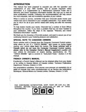 3
3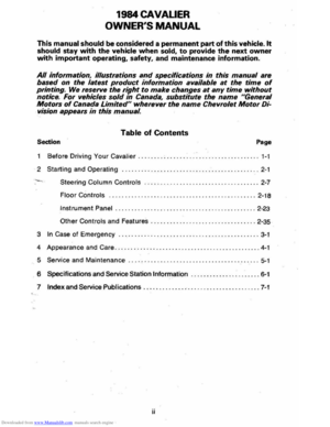 4
4 5
5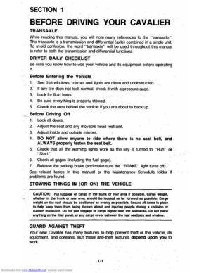 6
6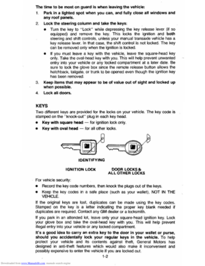 7
7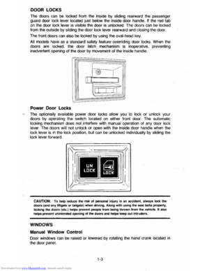 8
8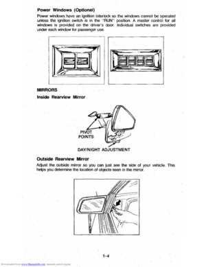 9
9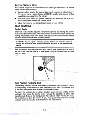 10
10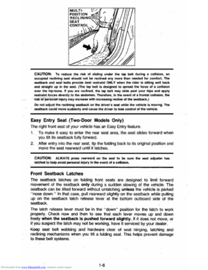 11
11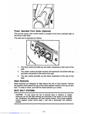 12
12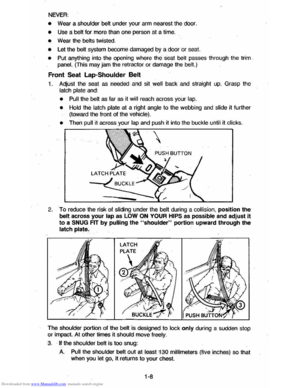 13
13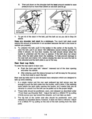 14
14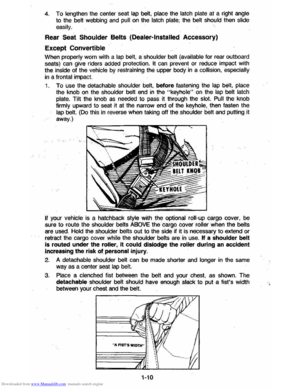 15
15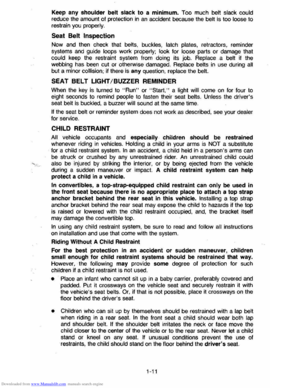 16
16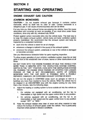 17
17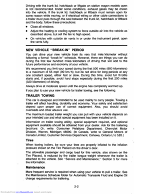 18
18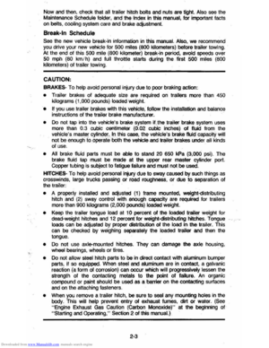 19
19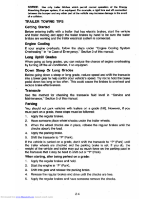 20
20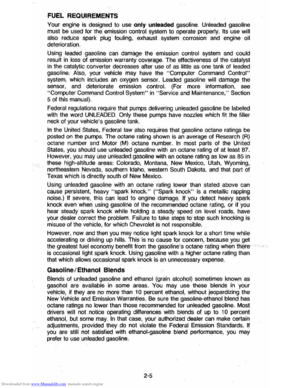 21
21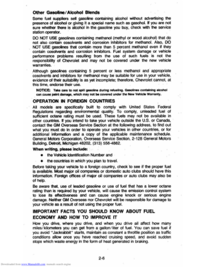 22
22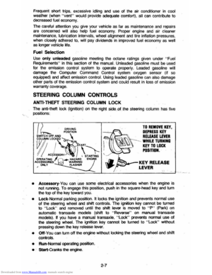 23
23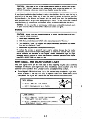 24
24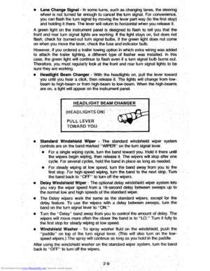 25
25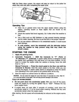 26
26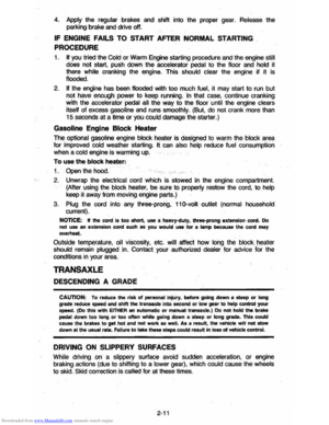 27
27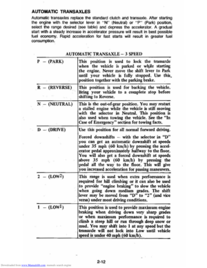 28
28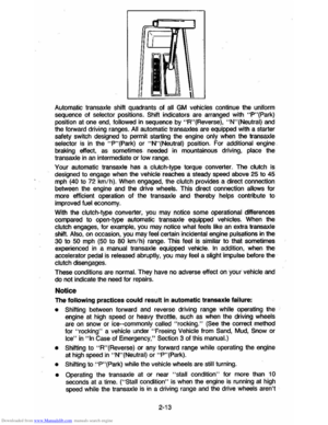 29
29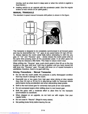 30
30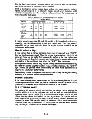 31
31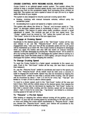 32
32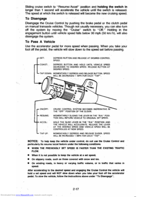 33
33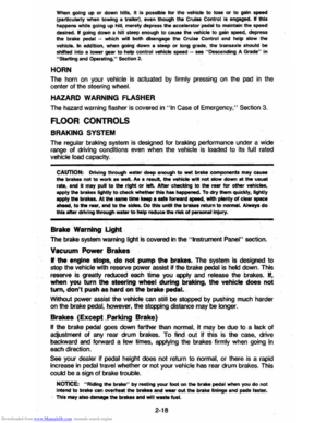 34
34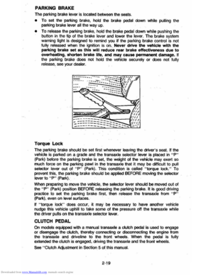 35
35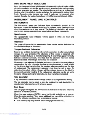 36
36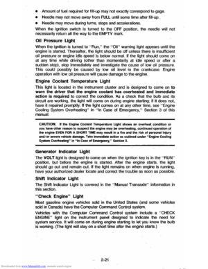 37
37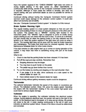 38
38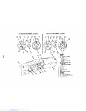 39
39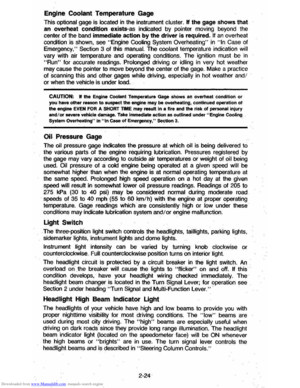 40
40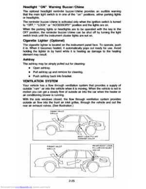 41
41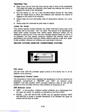 42
42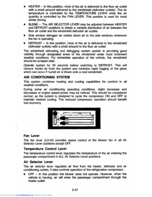 43
43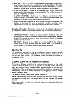 44
44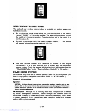 45
45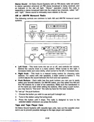 46
46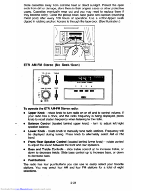 47
47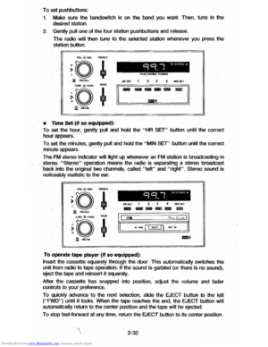 48
48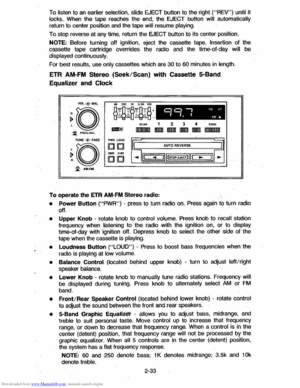 49
49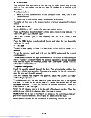 50
50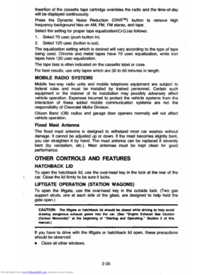 51
51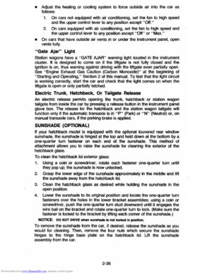 52
52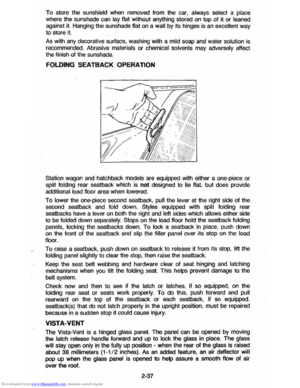 53
53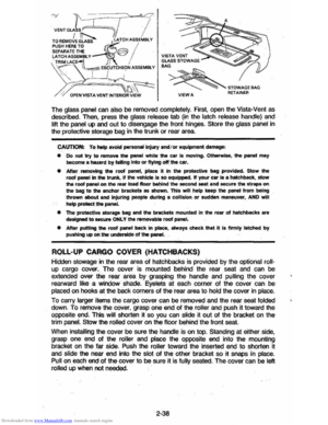 54
54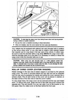 55
55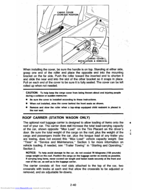 56
56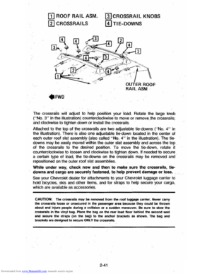 57
57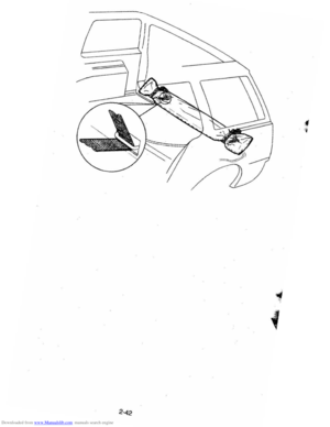 58
58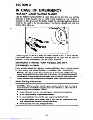 59
59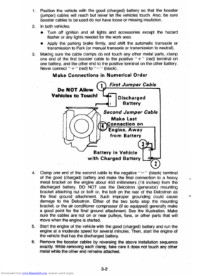 60
60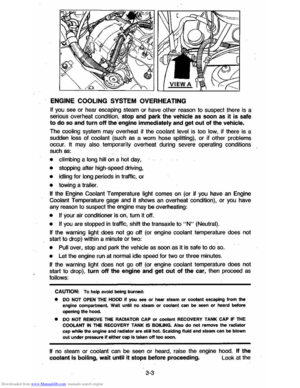 61
61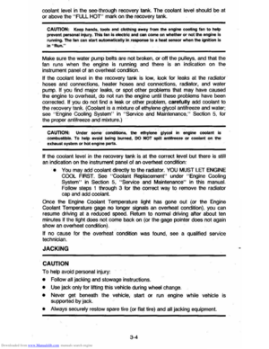 62
62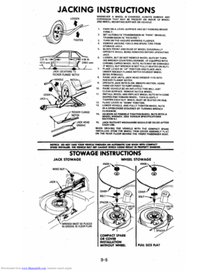 63
63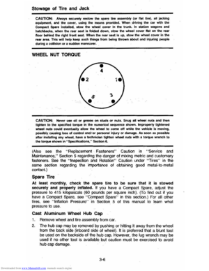 64
64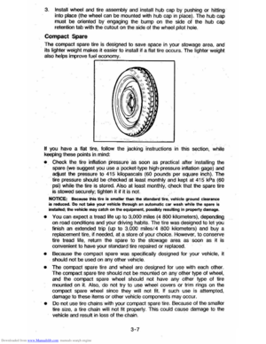 65
65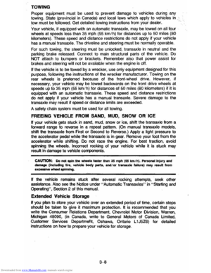 66
66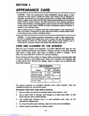 67
67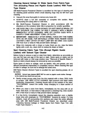 68
68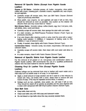 69
69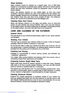 70
70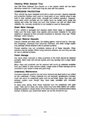 71
71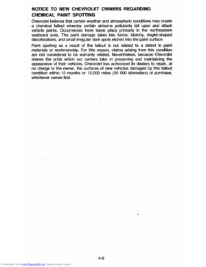 72
72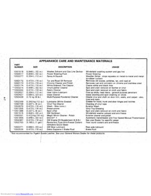 73
73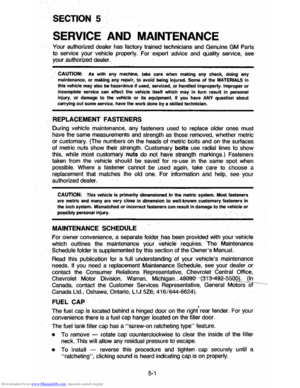 74
74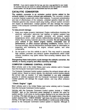 75
75 76
76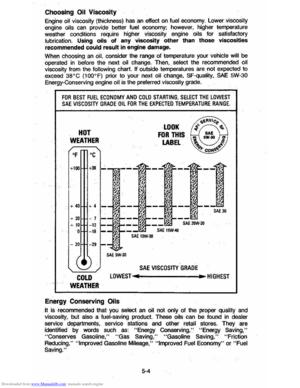 77
77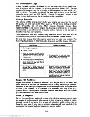 78
78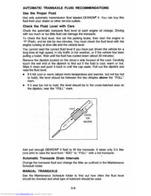 79
79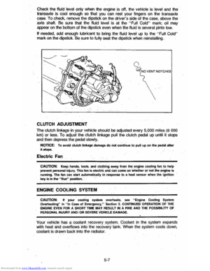 80
80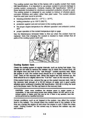 81
81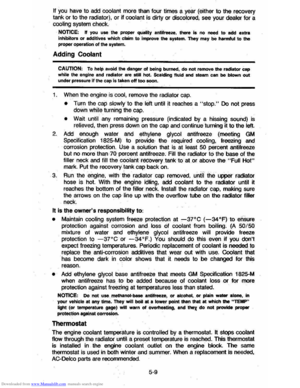 82
82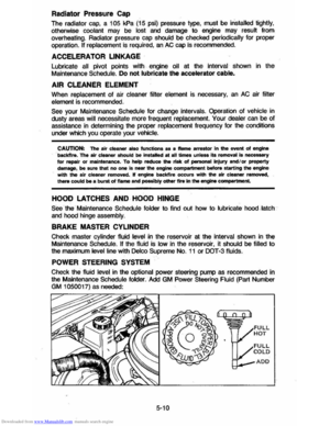 83
83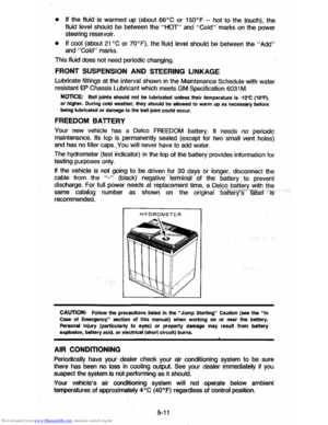 84
84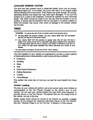 85
85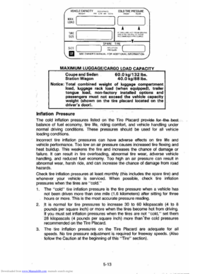 86
86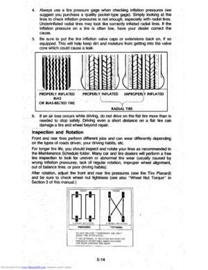 87
87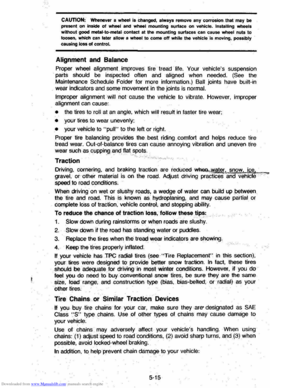 88
88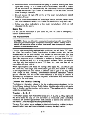 89
89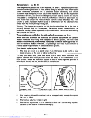 90
90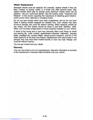 91
91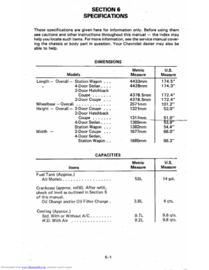 92
92 93
93 94
94 95
95 96
96 97
97 98
98 99
99 100
100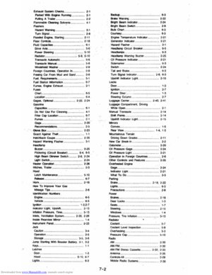 101
101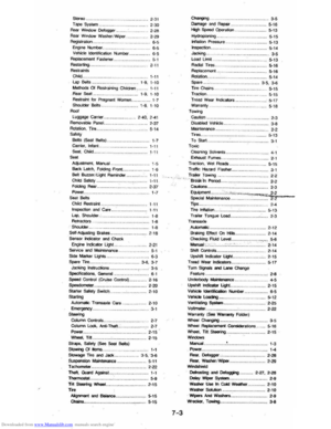 102
102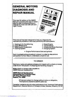 103
103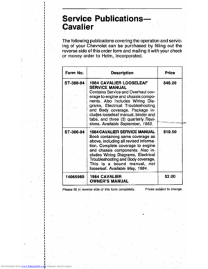 104
104