Page 33 of 105

Downloaded from www.Manualslib.com manuals search engine Sliding cruise switch to "Resume/ Accel" position and holding the switch in
longer than 1 second will accelerate the vehicle until the switch is released. The speed at which the switch is released will become the new cruising speed.
To Disengage
Disengage the Cruise Control by pushing the brake pedal or the clutch pedal on manual transaxle vehicles. Though not usually necessary, you can also turn
off the system by moving the
"Cruise" switch to "Off." Holding in the
engagement button until vehicle speed falls below 30 mph (50 km/h), will also
disengage the system.
To Pass A Vehicle
Use the accelerator pedal for more speed when passing. When you take your
foot off the
pedal, the vehicle will slow down to the speed set before passing.
SET: DEPRESS BUTTON AND RELEASE AT DESIRED CONTROL SPEED.
DEPRESS BUTTON AND HOLD UNTIL VEHICLE SPEED
DECREASES TO DESIRED SPEED. RELEASE BUTTON AT DESIRED SPEED.
TAP DOWN: MOMENTARILY DEPRESS AND RELEASE BUTTON. SPEED I BE DECREASED 1 MPH FDA EACH "TAP".
ON/OFF: CRUISE CONTROL SYSTEM BECOMES INOPERATIVE THE "OFF" POSITION OF THE SLIDER.
RESUME:
MOMENTARilY SLIDING THE LEVER IN THE "R/A" POSI
TION WILL RETURN VEHICLE TO ORIGINAL SET SPEED.
ACCEl: HOLD THE SLIDE LEVER IN THE "RIA" POSITION AND THE veHICLE WILL ACCELERATE. RELEAse THE LEVER AT THE DESIRED SPEED AND VEHICLE SPEED WILL BE CONTROLLED AT NEW SPEED.
TAP UP: MOMENTARILY DEPRESS AND RELEASE SLIDER. SPEED WILL BE INCREASED 1 MPH FOR EACH "TAP".
NOTICE: To help keep the vehicle under control, do not use the Cruise Control and
particularly its resume/accel feature under the following conditions:
• WHEN THE PREVIOUSLY SET SPEED IS· FASTER THAN THE EXISTING TRAFFIC
FLOW.
• When
it is not possible to keep the vehicle at a set speed.
• On slippery roads, such as those covered with snow and ice.
• On winding roads, in heavy or varying traffic volume, or in traffic that varies in speed.
After accelerating
to the desired speed and engaging the Cruise Control the vehicle will hold a set speed and will· NOT slow down when you take your foot off the accelerator
pedal. To slow the vehicle,follow the instructions above under "To Disengage".
2-17
Page 34 of 105
, even though the Cruise Contr")
Downloaded from www.Manualslib.com manuals search engine When_ going up or down hills. it ~ ~ tor the vehk:1e to toM 011 to gain apHCI (.,.rticu"Y when towing I trailer), even though the Cruise Control is enpgecL • this happens while going up hin, merely depress the accelerator pedal to maintain the speed desired. If going down a hili steep enough to cau .. thl vehie'" to gain speed, depress the brake pedal •• which will both dl .. ngage the Cruise Control and help .lOw the vehicle. In addition, when going down a steep or lang grade . the transaxle shoUld be shifted into I lower gear to help control vehicte speed •• see "Descending A Grade " in "Starting and Operating," Section 2.
HORN
The horn on your vehicle is actuated by firmly pressing on the ped in the
center of the steering
wheel.
HAZARD WARNING FLASHER
The hazard warning flasher is covered in "In Case of Emergency," Section 3.
FLOOR CONTROLS
BRAKING SYSTEM
The regular braking system is designed for braking performance under a wide
range of driving cond~ions even when the vehicle is loaded to ~ lull rated
vehicle toad capacity .
CAUTION: Driving through water deep enough to wet brake components may cau .. the brakea nat to work .. welL -M a reaul, the vehIde wi. not aIow down .. the usu.I _, ond M may pull 10 "'" right Of ..... _ 0"'-""'11 to "'" _ tor _ .-.os,
-'1 "'" ...... lightly 10 check __ .... "-'"
apply the blakes. At the .. me time ""' .. .... torw.rd apeed, with. plenty of clear apace ....... to the .,..,. II1CI to the sidea. Do this-unUl the brIkaI return to notmIt. Always do __ driving 1hrougII_ to help _ "'" _ oI ........ lnjuty.
Brake Warning lJg/rt
The brake system warning light is covered in the '.' lnstrumentPanel" section.
Vacuum Power Brakes
• the engine stops, do not pump the brakes. The system is designed to stop the vehicle with reserve power assist n the brake pedal is held dOwn. This
reserve is
greatly reduced each time you apply and release the brakes. II,
when you turn the atMring wheel during braking, the vehic:1e does not turn, don't push as hard on the brake pedal •.
Without power assist the vehicle can still be stopped by pushing much harder
on the brake
pedal. however. the stopping distance may be longer.
Brakes (Except ,Parking Brake)
H the brake pedaJ goes down farther than normal, ~ may be due to a lack of
adjustment of any rear drum
brakes. To find. out if this is the case. drive
backward and forward a few times. applying the brakes firmly when going in
each direction.
See your dealer n pedal height dOes not retum to normal, or there is a rapid
increase in pedal travel whether or not your vehicle has rear drum brakes. This
could be a sign of brake trOUble.
NOTICE: "FtidInsI the brake" by resting yow i0oi on thl brau pedal when you do not Intend 'to brake CIIf1 overhMI: the brIkM and ...... out the brake InInga and p..ts faster. , ThI. mIIy alSo dllNlge the brakes Mtd will wasta fuel.
2-18
Page 35 of 105

Downloaded from www.Manualslib.com manuals search engine PARKING BRAKE
The parking brake lever is located between the seats .
• To set the parking brake, hold the brake pedal down while pulling the
parking brake
lever all the way up.
• To release the parking brake, hold the brake pedal down while pushing the
button in the tip of the brake
lever and lower the lever. The brake system
warning light is designed to remind you H the parking brake control is not fully released when the ignition is on. Never drive the vehicle with the
parking brake set as this will reduce rear brake effectiveness due to
overheating, shorten brake life, and may cause permanent damege, If
the parking brake does not hold the vehicle securely or does not fully release , see your dealer .
Torque Lock
The perking brake should be set first whenever leaving the driver's seat. If the vehicle is parked on a grade and the transaxle selector lever is placed in "P"
(Park) before the parking brake is set, the weight 01 the vehicle may exert so
much force on the parking pawl in the transaxle that it may be difficult to pull
selector lever out of "P" (Park). This condition Is called "torque lock." To
prevent this, the parking brake should be applied BEFORE moving the selector lever to "P" (Park).
When preparing to move the
Vehicle , the selector lever should be moved out of the "P" (Park) position BEFORE releasing the parking brake. It is good driving
practice to
set the parking brake first. then release the transaxle from "P" (Park), even on level surfaces .
n "torque lock" does oocur, it may be necessary to have another vehicle
nudge this vehicle uphill to take some of the pressure off the transaxle while
the driver pulls on the transaxle selector lever.
CLUTCH PEDAL
On models equipped with a manual transaxle a clutch pedal is used to engage
or disengage the clutch, thereby connecting or disconnecting the engine from
the transaxle and dliveline to the front wheels . When the pedal is fully
extended the clutch is engaged, driving the transaxle and the front wheels .
See "Clutch Adjustment in Section 5 of this manual.
2·19
Page 36 of 105

Downloaded from www.Manualslib.com manuals search engine DISC BRAKE WEAR INDICATORS
Front disc brake pads have buin-in wear indicators which should make a high
pitched squealing or cricket-like warning sound when the brake pads are worn
to where new pads are needed . The sound will oome and
go. or be heard all the time when the vehicle is moving and when the brake pedal is pushed down
firmly. Expensive rotor damage can result if pads are not replaced when needed. See also the brake checks listed in the Maintenance Schedule folder.
INSTRUMENT PANEL AND CONTROLS
INSTRUMENTS
The instruments . gages and indicator lights conveniently grouped in the
instrument
cluster are designed to tell you at a glance many important things
about the performance of your Vehicle . The following information will enable
you to more quickly understand and properly interpret these instruments.
Speedometer
The speedometer hand indicates vehicle speed in miles per hour and
kilometers per hour.
Odometer
The group of figures in' the speedometer lower center section indicates the
accumulated mileage or kilometers .
Tamper-Resistant Odometer
Federal law prohibits tampering with vehicle odometers to aner accumulated
mileage. For your protection the odometer of this vehicle is designed with
tamper-resistant features to indicate
tarnpetiog . " silver lines appear vertically
between odometer numerals. it Is likely that the odometer has been turned
back or reversed . The mileage shown may not be actual. .
Whenever a new odometer is installed and cannot be set to the same mileage registered on the prior odometer . the law requires the owner to install a label
on thedriver's door frame to show the previous odometer reading and the date
of rep~. The · replacement odometer must then be set to zero . To
determine the actual vehicle
mileage. add the mileage shown on the label to . the current odometer reading. If the replacement odometer can be set up to
the same mileage as the prior odometer. no door frame
label is needed.
Trip Odometer
A trip odometer is used to record mileage on trips or during extended driving.
The trip odometer can be reset to zero by pushing the knob located in the
speedometer /odometer face until all zeros appear.
Fuei Gage
The fuel gage will register the APPAOXIMA TE fuel level in the tank. when the
ignition is in the RUN position .
When the gage registers EMPTY. some
fuel is still available as a reserve .
When the gage registers FULL. some additional fuel can still be added to the
tank . The fOllowing oonditions may be oonsidered normal:
•
Fuel station pump may shut off before fuel gage indicates FULL .
2-20
Page 37 of 105

Downloaded from www.Manualslib.com manuals search engine • Amount of fuel required for fill-up may not exactly correspond to gage.
• Needle may not move away from FULL until some time after fill-up.
• Needle may move during turns; stops and accelerations.
When the ignition switch is turned to the OFF position, the needle will not
necessarily return
all the way to the EMPTY mark.
Oil Pressure Light
When the ignition is turned to "Run," the "Oil" warning light appears until the
engine is started. Thereafter, the light should be off unless there is insufficient
oil pressure or engine idle speed is below normal. If the light should come on
at any time while driving (other than momentarily at idle speed or after a
sudden stop), stop immediately and investigate the cause of
low oil pressure.
This could possibly be caused by low oil level in the crankcase. Engine
operation with low oil pressure will 9ause damage to the engine.
Engine Coolant Temperature Light
This light is located in the instrument cluster and is designed to come on to warn the driver that the engine coolant has overheated and immediate
action is required to correct the condition. As a check that the bulb and its
circuit are working, the light will come on during engine starting; if it does not,
have it repaired
promptly. If the light comes on at any other time, see "Engine
Cooling System Overheating" in "In Case of Emergency," Section 3 of this manual.
CAUTION: It the Engine Coolant Temperature Light shows an overheat condition or you have other reason to suspect the engine may be overheating, continued operation of the engine EVEN FOR A SHORT TIME may result in a fire and the risk of personal injury and/or severe vehicle damage. Take immediate action as outlined under "Engine Cooling System Overheating" in "In Case of Emergency," Section 3.
Generator Indicator Light
The VOLT light is designed to come on when the ignition key is in the "RUN" position, but before the engine is started. After the engine starts, the light
should go out and remain out. If the light remains· on when engine is running,
have your authorized
dealer locate and correct the trouble as soon as possible.
Shift Indicator Light
The Shift Indicator Light is covered in the "Manual Transaxle" information in
this section.
"Check Engine" Light
Most gasoline engine vehicles sold in the Unijed States (and some vehicles
sold
in Canada) have the Computer Command Control system.
Vehicles with the Computer Command Control system include a "CHECK
ENGINE" light
on the instrument panel designed to indicate the need for
system service. It will come on during engine starting to let you know the bulb
is working. (The light will stay on a short time after the engine starts.)
2-21
Page 38 of 105

Downloaded from www.Manualslib.com manuals search engine Have the system repaired n the "CHECK ENGINE" light does not come on during engine starting. If the light comes on, either intermittently or
continuously while driving, service to the Computer Command Control system
is required. AHhough in most cases the vehicle is drivable, and does not
require towing, see your authorized
dealer as soon as possible for service of
the system.
Continued driving without having the Computer
Command Control system serviced could cause damage to the emission control system. It could also affect fuel economy and drivability.
See also "Computer Command Control system" in Section 5 of this manual.
Brake System Warning Light
The regular braking system is a dual system designed so that one part will
provide some braking if there is a
loss of hydraulic pressure in the other part of
the system. The system has a
"BRAKE" warning light located in the
instrument panel. The "BRAKE" light is designed to come on briefly during
engine starting so you can check that the bulb is okay. To serve as a reminder,
the
light should stay on when the parking brake is not fully released and the
ignition is
on. Have the system repaired if the light does not come on when it should. This warning light does not do away with the need for brake inspection
and maintenaflce. The brakelluid level must be checked regularly. See your
Maintenance Schedule folder for other brake checks.
I! the light remains on aller engine start up or comes on during operation of the vehicle, it may mean that there is something wrong with part of the brake
system.
What
to do:
1. Check to see that the parking brake has been released. I! it has been:
2. Pull off the road and stop carefully. Remember that:
• Stopping distances may be longer.
•
You may have to push harder on the pedal.
•
The pedal may go down farther than normal.
3. Tryout the brakes by starting and stopping on the road shoulder--then:
• I! you judge it to be safe, drive cautiously at a safe speed to the
nearest dealer for repair. Or,
• Have vehicle towed to the nearest dealer for repair.
Continued driving without getting necessary repairs
could be dangerous.
Tachometer
The optional tachometer indicates the speed of the engine in revolutions per
minute. The indicated number, times
100, gives the engine speed. Operating
the engine with the tachometer reading in the color-coded high-speed area
could lead to serious engine damage.
Voltmeter
When the engine is operating, the voltmeter indicates the electrical system
voltage. During minimum electrical load, the pointer will read to the right of the
center.
As the electrical load is increased, or in stop-and-go driving, the pointer
will rotate to the Ieli. A meter reading continuously in the left or right zone
indicates
an electrical system failure. Cause of the failure should be determined and corrected.
2-22
Page 39 of 105
Downloaded from www.Manualslib.com manuals search engine '" ,
t:l
STANDARD INSTRUMENT CLUSTER
IJ
12
OPTIONAL INSTRUMENT CLUSTER
~~~~-:'----,~~:
l'l
1l
10
L Speedometer 2. Odometer 3. Trip ()jometer lif equipped) 4. Fuel Gage 5. Warning Lights Brake, Fasten Belts, Check. Engine Volts, Temperature, Oil Pressure 6. Shift up Lt. (on "ME"only) 7. Warning Gages Temperature, on Pressure, Volts 8. Turn Indicators 9. High Beam 10. Tachomet er 11. A/C Outlet 12. Clock. (if equipped) 13. Radio 14. Heater & Opt. Ale Control 15. Glove Box 16. Lig ht Switch 17. Rear Window Defogger (Opt.) 18. Rear Window WiperlWasher (Opt.) 19. Cigare tt e Lighter (Opt.) 20, Tailgat e Ajar Lt.
Page 40 of 105

Downloaded from www.Manualslib.com manuals search engine Engine Coolant Temperature Gage
This optional gage is located in the instrument cluster. If the gage shows that
an overheat condition exists-as indicated by pointer moving beyond the
center of the band immediate action by the driver is required. If an overheat
condition is shown, see "Engine
Cooling System Overheating" in "In Case of
Emergency,"
Section 3 of this manual. The coolant temperature indication will VaIY with air temperature and operating conditions. The ignition must be in
"Run" for accurate readings. Prolonged driving or idling in very hot weather
may cause the pointer to move beyond the center of the gage. Make a practice
of scanning this and other gages
while driving, especially in hot weather and!
or when the
vehicle is under load.
CAUTION: II the Engine Coolant Temperature Gage shows an overheat condition or you have other reason to suspect the engine may be overheating, continued operation of the engine EVEN FOR A SHORT TIME may result in a fire and the risk of personal injury and/or severe vehicle damage. Take immediate action as outlined under "Engine Cooling System Overheating" in "In Case of Emergency," Section 3.
Oil Pressure Gage
The oil pressure gage indicates the pressure at which oil is being delivered to
the vaIiOUS paIls of the engine requiring lubrication. Pressures registered by
the gage may
vBIY according to outside air temperatures or weight of oil being
used. Oil pressure of a cold engine being operated at a given speed will be
somewhat higher than when the engine is at normal operating temperature at
the
SaIne speed. Prolonged high speed operation on a hot day at the given
speed will
resuH in somewhatlower oil pressure readings. Readings of 205 to
275 kPa
(30 to 40 psi) may be considered normal during moderate road
speeds of 35 to 40 mph (55 to 60 km!h) with the engine at proper operating
temperature. Gage readings which are consistently high
or low under these conditions may indicate lubrication system and/ or engine malfunction.
Light Switch
The three· position light switch controls the headlights, taillights, paIking lights,
sidemaIker lights,
instrument lights and dome lights.
Instrument light intensity can be varied by turning knob clockwise or
counterclockwise. Full counterclockwise position turns on interior light.
The headlight circuit is protected by a circuit breaker in the
light switch. An overload on the breaker will cause the lights to "flicker" on and off. If this
condition
develops, have your headlight wiring checked immediately. The
headlight beaIn changer is located in the Turn Signal Lever; for operation see
Section 2 under heading "Turn Signal and Muiji-Function Lever."·
Headlight High Beam Indicator Light
The headlights of your vehicle have. high and low beams to provide you with
proper nighttime visibility for most driving conditions. The
"low" beams are
used during most city driving. The
"high" beams are especially useful when
driving on daIk roads since they provide long range illumination. The headlight
beam indicator light (located on the speedometer face) will be ON whenever
the high beams or "brights" are in use. The turn
signal lever controls the
headlight beaIns and is described in "Steering Column Controls."
2-24
 1
1 2
2 3
3 4
4 5
5 6
6 7
7 8
8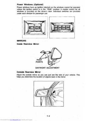 9
9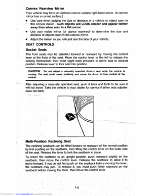 10
10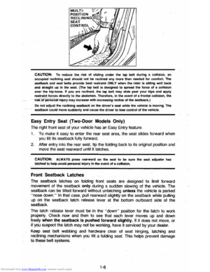 11
11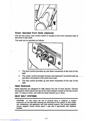 12
12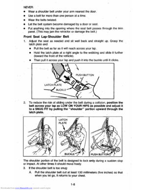 13
13 14
14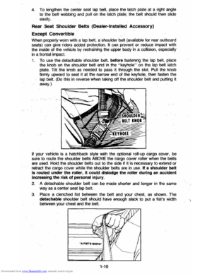 15
15 16
16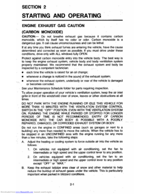 17
17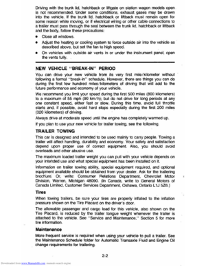 18
18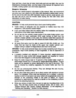 19
19 20
20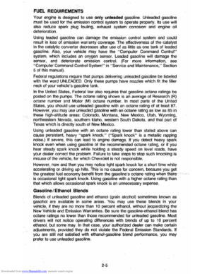 21
21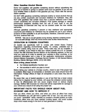 22
22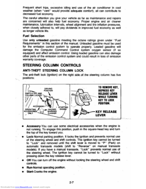 23
23 24
24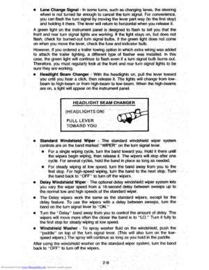 25
25 26
26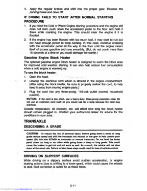 27
27 28
28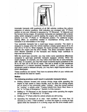 29
29 30
30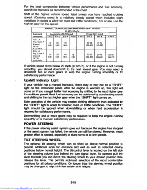 31
31 32
32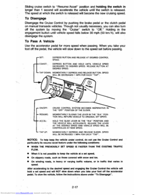 33
33 34
34 35
35 36
36 37
37 38
38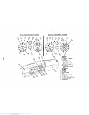 39
39 40
40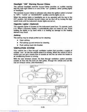 41
41 42
42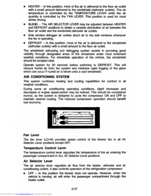 43
43 44
44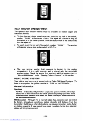 45
45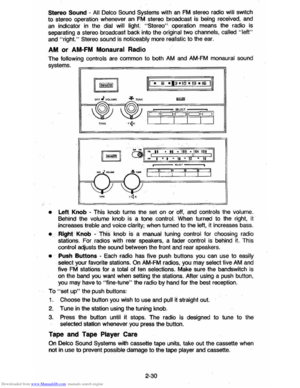 46
46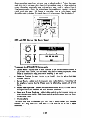 47
47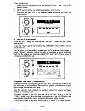 48
48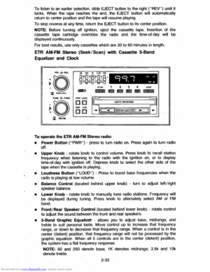 49
49 50
50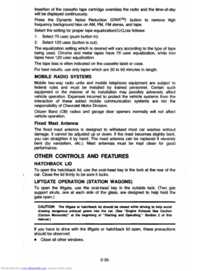 51
51 52
52 53
53 54
54 55
55 56
56 57
57 58
58 59
59 60
60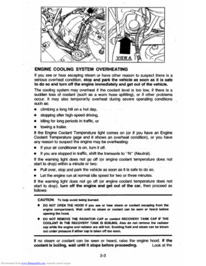 61
61 62
62 63
63 64
64 65
65 66
66 67
67 68
68 69
69 70
70 71
71 72
72 73
73 74
74 75
75 76
76 77
77 78
78 79
79 80
80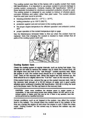 81
81 82
82 83
83 84
84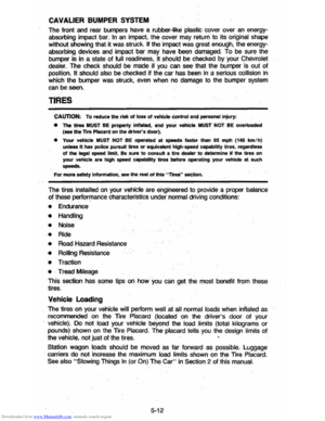 85
85 86
86 87
87 88
88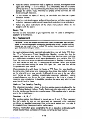 89
89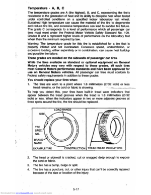 90
90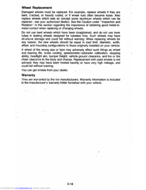 91
91 92
92 93
93 94
94 95
95 96
96 97
97 98
98 99
99 100
100 101
101 102
102 103
103 104
104")