Page 637 of 875
GM – CAMARO 1982-1992 – Repair Guide (Checked by WxMax) 637
Fig. 4: 5.0L and 5.7L (VIN 8) Engines - Engine firing order: 1-8-4-3-6-5-7-2-
Distributor Rotation: Clockwise
It should be remembered that resistance is also a function of length; the longer
the wire, the greater the re sistance. Thus, if the wires on your car are longer
than the factory originals, resistance will be higher, qui te possibly outside these
limits.
When installing new wires, r eplace them one at a time to avoid mix-ups. If it
becomes necessary to remove all of the wires from the distributor cap or coil
packs at one time, take the time to label the distributor cap/coil pack towers to
denote the cylinder number of the wire fo r that position. When this is done,
incorrect positioning of wires can more eas ily be avoided. Start by replacing the
longest one first. Route the wire over the same path as the original and secure
in place.
Page 651 of 875

GM – CAMARO 1982-1992 – Repair Guide (Checked by WxMax) 651
Fig. 6: Removing the distri butor cap. Notice that all towers on cap are labeled
with the corresponding engine cylinder number.
ROTOR 1. Disconnect the negative battery cable.
2. Remove the distributor cap.
3. Unscrew the two rotor attaching screws and then lift off the rotor.
4. For installation, make sure the roto r is positioned in the correct direction
and tighten the retaining screws.
CAPACITOR
The capacitor, if equipped, is part of the ignition coil wire harness assembly.
Since the capacitor is used only for radio noise suppres sion, it will seldom need
replacement.
1. Disconnect the negative battery cable.
2. Remove the distributor cap and rotor.
3. Remove the capacitor attaching screws and unplug the connector from
the module. Remove the module.
To install: 4. Plug the connector into the capacitor. Install the capacitor and secure in
place using the mounting screws. Be sure the ground lead is under the
screw.
5. Install the rotor and distributor cap.
Page 714 of 875

GM – CAMARO 1982-1992 – Repair Guide (Checked by WxMax) 714
4. Start the car and observe the fuel
pressure reading. It should be 9-13 psi
(62-90 kPa).
5. Relieve the fuel pressure.
6. Remove the fuel pressure gauge.
7. Reinstall the fuel line.
8. Start the car and che ck for fuel leaks.
9. Remove plug covering THERMAC va cuum port on the TBI and install the
air cleaner.
THROTTLE BODY
REMOVAL & INSTALLATION 1. Relieve the fuel system pressure.
2. Disconnect the THERMAC hose from the engine fitting and remove the
air cleaner.
3. Detach the electrical connectors at the idle air control, throttle position
sensor, and the injector.
4. Disconnect the throttle linkage, re turn spring, and cruise control (if
equipped).
5. Disconnect the throttle body vacuum hoses, fuel supply and fuel return
lines.
6. Disconnect the 3 bolts securing the throttle body and remove the throttle
body.
7. To install, reverse the removal procedures. Replace the manifold gasket
and O-rings.
8. Perform the minimum idle speed adjustment, if necessary.
Fig. 1: Single injector TBI unit
Page 716 of 875

GM – CAMARO 1982-1992 – Repair Guide (Checked by WxMax) 716
INJECTOR REPLACEMENT
Use care in removing injectors to prev
ent damage to the electrical connector
pins on top of the injector, the fuel injector fuel filter and nozzle. The fuel injector
is serviced as a complete assembly on ly and should never be immersed in any
type of cleaner.
SINGLE INJECTOR UNITS 1. Relieve the fuel system pressure.
2. Remove the air cleaner.
3. Detach the injector connector by squeezing the two tabs together and
pulling straight up.
4. Remove the screws securing the fuel meter cover. Note the location of
any short screws for correct placement during reassembly.
CAUTION - DO NOT remove the four screws se curing the pressure regulator to
the fuel meter cover. The fuel pressure regulator includes a large spring under
heavy tension which could cause personal injury if released.
5. With the old fuel meter gasket in place to prevent damage to the casting,
use a prytool and fulcrum to pry the inje ctor carefully until it is free from
the fuel meter body.
6. Remove the injector.
7. Remove the large O-ring and steel back-up washer at the top of the
injector cavity in the fuel meter body.
8. Remove the small O-ring located at the bottom of the injector cavity.
To Install: 9. Lubricate the new, small O-ring with automatic transmission fluid; then,
push the new O-ring on the nozzle end of the injector up against the
injector fuel filter.
10. Install the steel backup washer in the recess of the fuel meter body.
Lubricate the new large O-ring with automatic transmission fluid, then
install the O-ring directly above t he backup washer, pressing the O-ring
down into the cavity recess. The O-ri ng is properly installed when it is
flush with the casting surface.
WARNING - Do not attempt to reverse this procedure and install the backup
washer and O-ring after the injector is located in the cavity. To do so will
prevent proper seating of the O-ring in th e cavity recess which could result in a
fuel leak and possible fire.
11. Install the injector by using a pushing/twisting mo tion to center the nozzle
O-ring in the bottom of the injector cavity and aligning the raised lug on
the injector base with the notch cast into the fuel meter body. Push down
on the injector making sure it is fully seated in the cavity. Injector
installation is correct when the lug is seated in the notch and the
electrical terminals are parallel to the throttle shaft.
Page 718 of 875

GM – CAMARO 1982-1992 – Repair Guide (Checked by WxMax) 718
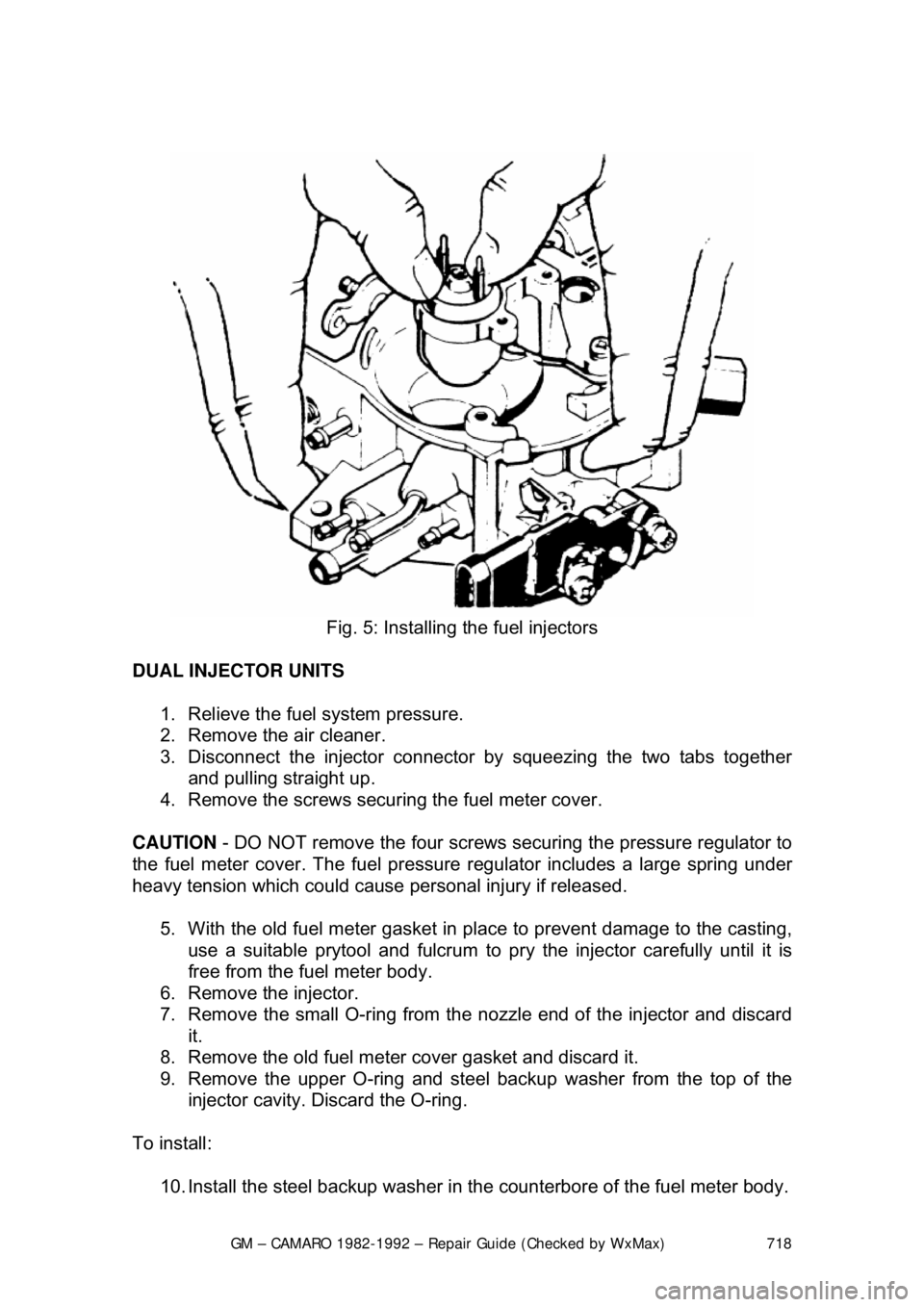
Fig. 5: Installing the fuel injectors
DUAL INJECTOR UNITS 1. Relieve the fuel system pressure.
2. Remove the air cleaner.
3. Disconnect the injector connector by squeezing the two tabs together and pulling straight up.
4. Remove the screws securi ng the fuel meter cover.
CAUTION - DO NOT remove the four screws securing the pressure regulator to
the fuel meter cover. The fuel pressure regulator includes a large spring under
heavy tension which could cause personal injury if released.
5. With the old fuel meter gasket in pl ace to prevent damage to the casting,
use a suitable prytool and fulcrum to pr y the injector carefully until it is
free from the fuel meter body.
6. Remove the injector.
7. Remove the small O-ring from the nozzle end of the injector and discard
it.
8. Remove the old fuel meter cover gasket and discard it.
9. Remove the upper O-ring and steel ba ckup washer from the top of the
injector cavity. Discard the O-ring.
To install: 10. Install the steel backup washer in t he counterbore of the fuel meter body.
Page 734 of 875

GM – CAMARO 1982-1992 – Repair Guide (Checked by WxMax) 734
5. Install the throttle position sensor
. Make sure the TPS pickup lever is
located above the tang on the throttle actuator lever.
6. Install the TPS attaching screws.
7. Adjust the TPS voltage.
8. Reconnect the electrical connector.
9. Install the air cleaner.
IDLE AIR CONTROL VALVE
REMOVAL & INSTALLATION 1. Remove the air cleaner.
2. Detach the electrical connection fr om the idle air control assembly.
3. Using a 1
1/4 in. wrench, remove the IAC valve from the throttle body. On
IAC valves secured with screws, remove the attaching screws.
Before installing a NEW IAC valve, measur e the distance that the conical valve
is extended. Measurement should be made from the motor housing to the end
of the cone. Distance s hould be no greater than 1
1/4 in. (32mm). If the cone is
extended too far, damage may result when the motor is installed. If necessary,
push on the end of cone until it is retracted the correct distance.
4. Installation is the reverse of remo val. Torque threaded valves to 13 ft.
lbs. (17 Nm).
Fig. 1: IAC valve pintle measurement
Page 833 of 875

GM – CAMARO 1982-1992 – Repair Guide (Checked by WxMax) 833
1. Siphon some brake fluid from the ma
ster cylinder. Raise and support the
vehicle.
2. Remove the wheel and tire. Remo ve the brake hose from the strut.
3. Remove the caliper and support on a wire. Refer to Brakes for
procedures, then remove the hub-and-disc.
4. Remove the splash shield. Disc onnect the tie rod from the steering
knuckle.
5. Support the lower control arm and disconnect the ball joint from the
steering knuckle using tool J-24292A.
6. Remove the 2 bolts securing the stru t to the steering knuckle and remove
the steering knuckle.
To install: 7. Place the steering knu ckle into position and install the 2 bolts securing
the strut to the st eering knuckle.
8. Support the lower control arm and c onnect the ball joint to the steering
knuckle.
9. Connect the tie rod to the steering knuckle. Install the splash shield.
10. Install the caliper.
11. Install the brake hose from the strut. Install the wheel and tire.
12. Lower the vehicle and refill the master cylinder with brake fluid.
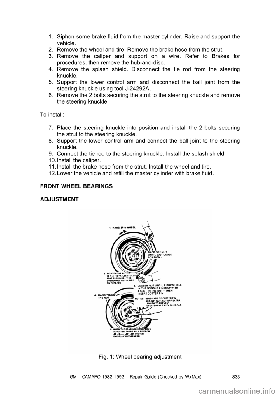
FRONT WHEEL BEARINGS
ADJUSTMENT
Fig. 1: Wheel bearing adjustment
Page 839 of 875

GM – CAMARO 1982-1992 – Repair Guide (Checked by WxMax) 839
COIL SPRINGS
REMOVAL & INSTALLATION
1. Raise the car by the frame so that the rear axle can be independently
raised and lowered.
2. Support the rear axle with a floor jack.
3. If equipped with brake hose attaching brackets, disconnect the brackets
allowing the hoses to hang free. Do not disconnect the hoses. Perform
this step only if the hoses woul d otherwise be stretched and damaged
when the axle is lowered.
4. Disconnect the track bar from the axle.
5. Remove the lower shock absorber bol ts and lower the axle. Make sure
the axle is supported securely on t he floor jack and that there is no
chance of the axle slipping after the shock absorbers are disconnected.
On vehicles equipped with a 4-cylinder engine, remove the driveshaft.
6. Lower the axle and remove the coil spring. Do not lower the axle past th\
e limits of the brake lines or the lines will be damaged.
To install: 7. Position spring with the axle lowered.
8. On vehicles equipped with 4-cylinder engines, install the driveshaft.
9. Raise the axle and install the lower shock absorber bolts.
10. Connect the track bar to the axle.
11. Connect the brake hose attaching brackets, if removed.
12. Remove the support from the rear axle.
13. Lower the vehicle.