Page 851 of 875

GM – CAMARO 1982-1992 – Repair Guide (Checked by WxMax) 851
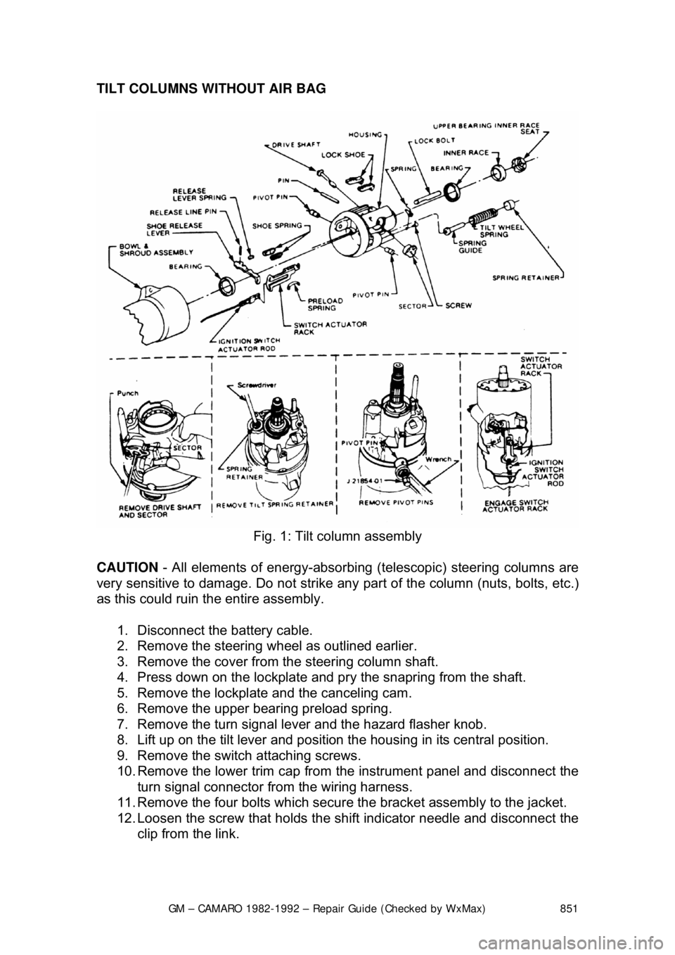
TILT COLUMNS WITHOUT AIR BAG
Fig. 1: Tilt column assembly
CAUTION - All elements of energy -absorbing (telescopic) steering columns are
very sensitive to damage. Do not strike any part of the column (nuts, bolts, etc.)
as this could ruin the entire assembly.
1. Disconnect the battery cable.
2. Remove the steering w heel as outlined earlier.
3. Remove the cover from the steering column shaft.
4. Press down on the lockplate and pr y the snapring from the shaft.
5. Remove the lockplate and the canceling cam.
6. Remove the upper bearing preload spring.
7. Remove the turn signal lever and the hazard flasher knob.
8. Lift up on the tilt lever and position the housing in its central position.
9. Remove the switch attaching screws.
10. Remove the lower trim cap from the instrument panel and disconnect the
turn signal connector from the wiring harness.
11. Remove the four bolts which secure the bracket assembly to the jacket.
12. Loosen the screw that holds the sh ift indicator needle and disconnect the
clip from the link.
Page 852 of 875

GM – CAMARO 1982-1992 – Repair Guide (Checked by WxMax) 852
13. Remove the two nuts fr
om the column support bracket while holding the
column in position. Remove the br acket assembly and wire protector
from the wiring, then l oosely install the support column bracket.
14. Tape the turn signal wires at the c onnector to keep them fit and parallel.
15. Carefully remove the turn signal switch and wiring from the column.
To install: 16. Carefully install the turn signal switch and wiring into the column.
17. Remove the tape from the turn signal wires.
18. Install the wire protecto r and, while holding the colu mn in position, install
the two nuts to the colu mn support bracket.
19. Connect the clip to the link and ti ghten the screw that holds the shift
indicator needle.
20. Install the four bolts which secure the bracket assembly to the jacket.
21. Connect the turn signal connector to the wiring harness and install the
lower trim cap to the instrument panel.
22. Install the switch attaching screws.
23. Install the turn signal lever and the hazard flasher knob.
24. Install the upper bear ing preload spring.
25. Install the lockplate and the canceling cam.
26. Press down on the lockplate and inst all the snapring to the shaft using a
new snapring.
27. Install the cover to t he steering column shaft.
28. Install the steering wheel.
29. Connect the battery cable.
Page 866 of 875

GM – CAMARO 1982-1992 – Repair Guide (Checked by WxMax) 866
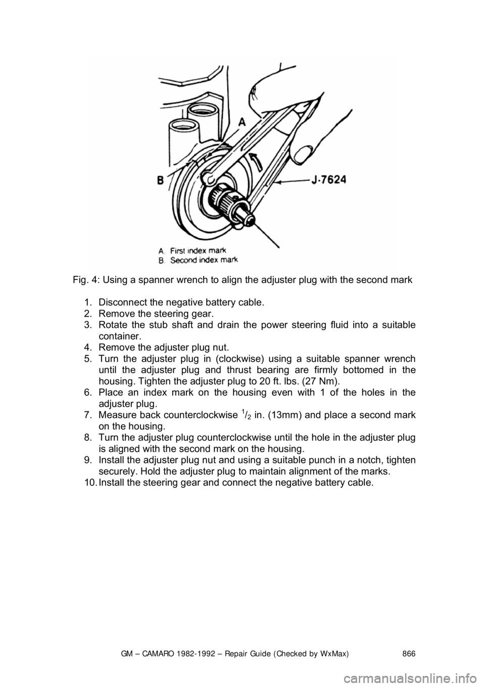
Fig. 4: Using a spanner wrench to align the adjuster plug with the second mark
1. Disconnect the negative battery cable.
2. Remove the steering gear.
3. Rotate the stub shaft and drain the power steering fluid into a suitable
container.
4. Remove the adjuster plug nut.
5. Turn the adjuster plug in (clock wise) using a suitable spanner wrench
until the adjuster plug and thrust bearing are firmly bottomed in the
housing. Tighten the adjuster plug to 20 ft. lbs. (27 Nm).
6. Place an index mark on the housi ng even with 1 of the holes in the
adjuster plug.
7. Measure back counterclockwise
1/2 in. (13mm) and place a second mark
on the housing.
8. Turn the adjuster plug counterclock wise until the hole in the adjuster plug
is aligned with the second mark on the housing.
9. Install the adjuster plug nut and using a suitable punch in a notch, tighten
securely. Hold the adjuster plug to ma intain alignment of the marks.
10. Install the steering gear and c onnect the negative battery cable.
Page 869 of 875
GM – CAMARO 1982-1992 – Repair Guide (Checked by WxMax) 869
4. Remove Pitman arm using spec
ial tool J-6632 or its equal.
5. Remove the steering box to fram e bolts. Remove the steering box.
On vehicles with power steering, remo ve the fluid hoses and cap them to
prevent foreign material from entering the system.
To install:
6. Position the steering box and secure with the steering box-to-frame bolts.
7. Install the Pitman arm to the matchmarks made earlier.
8. Install the Pitman arm nut and washer.
9. Install the retaining bolts at the st eering coupling to steering shaft flange.
10. Install the coupling shield.
11. Connect the negative battery cable.
POWER STEERING PUMP
REMOVAL & INSTALLATION
Fig. 1: Pulley removal