1982 CHEVROLET CAMARO instrument panel
[x] Cancel search: instrument panelPage 182 of 875

GM – CAMARO 1982-1992 – Repair Guide (Checked by WxMax) 182
ANTENNA
REMOVAL & INSTALLATION
Placement of tape on the right inner door edge will help prevent scratches
during the antenna removal an
d installation procedure.
1. Disconnect the negative battery terminal.
2. Remove the right side lower in strument panel sound insulator and
disconnect the antenna connection from the radio.
3. Raise and safely support the vehicle.
4. Disconnect the instrument panel harness from the radio.
5. Disconnect the power antenna lead, if equipped.
6. Disconnect the power antenna wire from the relay, if equipped.
7. Remove the right fender wheelhouse.
8. Loosen the fender-to-body attaching bolts and block the fender out.
9. Remove the antenna bezel and nut.
10. Remove the antenna assembly mounting screws.
11. Remove the grommet from the bul khead and pull the harness from the
vehicle interior.
12. Remove the antenna assembly from the vehicle.
In some cases, if the vehicle is equipped with a power antenna, it may be
repaired. Seek a profe ssional radio shop for pr oper repair of the antenna
assembly.
To install: 13. Install the antenna assembly into the vehicle.
14. Install the grommet and the harne ss into the vehicle interior.
15. Install the antenna assembly mounting screws.
16. Install the antenna bezel and nut.
17. Remove the fender block, tighten the fender-to-body attaching bolts.
Ensure any shims for the fender are reinstalled.
18. Install the right fender wheelhouse.
19. Lower the vehicle.
20. Connect the power antenna wire to the relay, if equipped.
21. Connect the power ant enna lead, if equipped.
22. Connect the instrument panel harness to the radio.
23. Connect the antenna connection to the r adio. Install the right side lower
instrument panel sound insulator
24. Connect the negative battery cable.
Page 198 of 875

GM – CAMARO 1982-1992 – Repair Guide (Checked by WxMax) 198
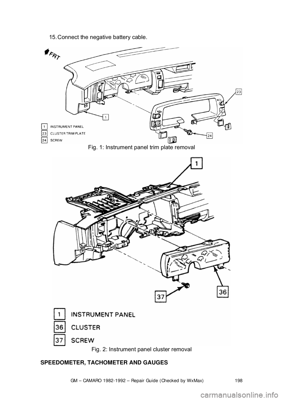
15. Connect the negative battery cable.
Fig. 1: Instrument panel trim plate removal
Fig. 2: Instrument panel cluster removal
SPEEDOMETER, TACHOMETER AND GAUGES
Page 200 of 875

GM – CAMARO 1982-1992 – Repair Guide (Checked by WxMax) 200
9. Lubricate the speedometer cable
with an appropriate lubricant, being
sure to cover the lower thirds of the cable.
10. Insert the cable into the casi ng, then connect the cable and casing
assembly to the speedometer.
11. Install the instrument cluster, then install the cluster attaching screws.
12. Install the instrument cluster trim plate.
13. On models without cruise control, connect the speedometer cable strap
at the power brake booste r. On models with cruise control, connect the
speedometer cable at the cr uise control transducer.
14. Connect the negative battery cable at the battery.
WIPER SWITCH
REMOVAL & INSTALLATION
The wiper switch is part of the multi-function lever, located on the steering
wheel column.
1. Disconnect the electrical connector of the multi-function lever, located
under the instrument panel.
2. Remove the protective cover from the wire.
3. Grasp the lever firmly, twist and pull (the tang on the lever must align
with the socket) the lever straight out.
4. Pull the wire through the steering column.
To install: 5. Slide a music wire tool through the steering column and connect the
lever wire to the tool wire; pull t he wire through the steering column.
6. Push the control lever into the sp ring loaded socket (be sure to align the
tang).
7. Install the protective cover to the wire.
8. Connect the electrical connector of the multi-function lever.
HEADLIGHT SWITCH
REMOVAL & INSTALLATION 1. Disconnect the negative batte ry cable at the battery.
2. Remove the four screws from insi de the defroster duct (instrument panel
pad securing screws).
3. Remove the screws which are under the lip of the instrument panel pad.
4. Remove the instrument panel pad.
5. On models equipped with air condition ing, remove the instrument panel
cluster bezel and the cluster.
6. Remove the radio speaker bracket.
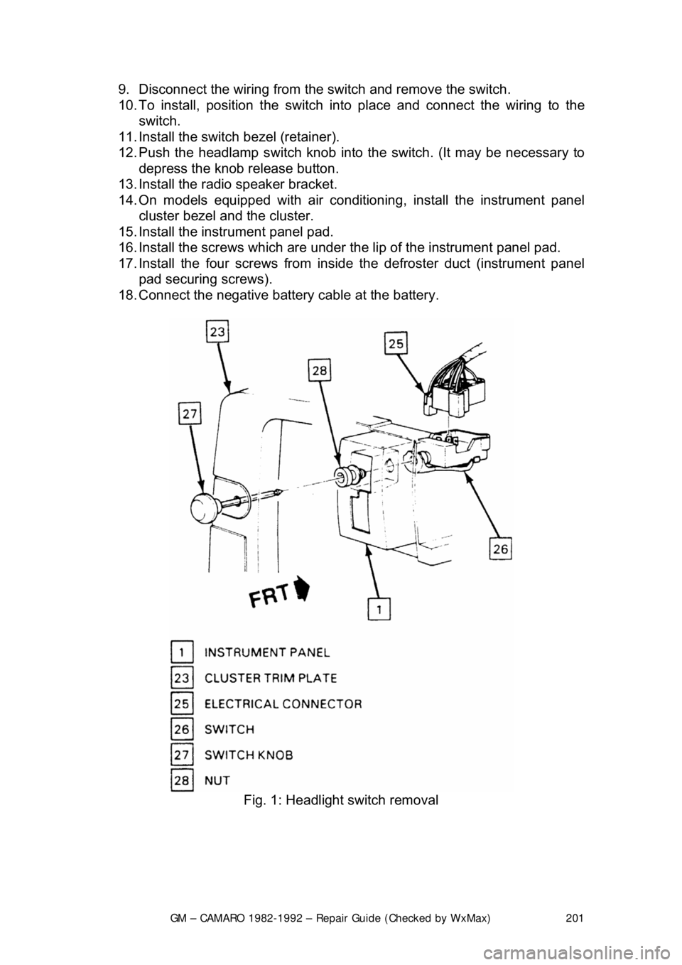
7. Pull the headlamp switch knob to the ON position, depress the locking
button for the knob and shaft (locat ed on the switch), and remove the
knob and shaft.
8. Remove the switch bezel (retainer).
Page 201 of 875

GM – CAMARO 1982-1992 – Repair Guide (Checked by WxMax) 201
9. Disconnect the wiring from the
switch and remove the switch.
10. To install, position t he switch into place and connect the wiring to the
switch.
11. Install the switch bezel (retainer).
12. Push the headlamp switch knob into the switch. (It may be necessary to
depress the knob release button.
13. Install the radio speaker bracket.
14. On models equipped with air conditioni ng, install the instrument panel
cluster bezel and the cluster.
15. Install the inst rument panel pad.
16. Install the screws which are under t he lip of the instrument panel pad.
17. Install the four screw s from inside the defroster duct (instrument panel
pad securing screws).
18. Connect the negative battery cable at the battery.
Fig. 1: Headlight switch removal
Page 219 of 875

GM – CAMARO 1982-1992 – Repair Guide (Checked by WxMax) 219
FUSE BLOCK
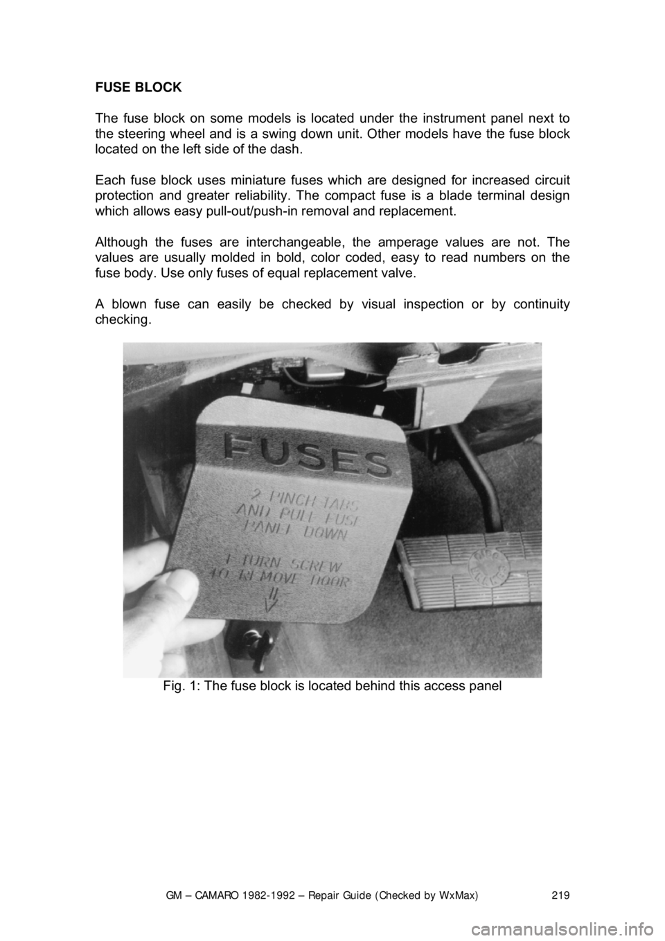
The fuse block on some models is loca
ted under the instrument panel next to
the steering wheel an d is a swing down unit. Other models have the fuse block
located on the left side of the dash.
Each fuse block uses miniature fuse s which are designed for increased circuit
protection and greater reliabi lity. The compact fuse is a blade terminal design
which allows easy pull-out/push- in removal and replacement.
Although the fuses are interchangeable , the amperage values are not. The
values are usually molded in bold, color coded, easy to read numbers on the
fuse body. Use only fuses of equal replacement valve.
A blown fuse can easily be checked by visual inspection or by continuity
checking.
Fig. 1: The fuse block is located behind this access panel
Page 223 of 875

GM – CAMARO 1982-1992 – Repair Guide (Checked by WxMax) 223
FUSIBLE LINKS
In addition to circuit breakers and fuses,
the wiring harness incorporates fusible
links to protect the wiring. Links are used rather than a fuse, in wiring circuits
that are not normally fused, such as th e ignition circuit. The fusible links are
color coded red in the charging and load circuits to match the color coding of
the circuits they protect. Each link is four gauges smaller than the cable it
protects, and is marked on the insulation with the gauge size because the
insulation makes it appear heavier than it really is. The engine compartment
wiring harness has several fusible links. The same size wire with a special
Hypalon insulation must be used w hen replacing a fusible link.
For more details, see the information on fusible links at the beginning of this
section.
The links are located in the following areas:
1. A molded splice at the starter solenoid Bat terminal, a 14 gauge red wire.
2. A 16 gauge red fusible link at the j unction block to protect the unfused
wiring of 12 gauge or larger wire. This link stops at the bulkhead
connector.
3. The alternator warning light and fiel d circuitry is protected by a 20 gauge
red wire fusible link used in the batte ry feed-to-voltage regulator number
3 terminal. The link is installed as a molded splice in the circuit at the
junction block.
4. The ammeter circuit is protected by two 20 gauge fusible links installed
as molded splices in the circuit at t he junction block and battery to starter
circuit.
REPLACEMENT 1. Determine the circuit that is damaged.
2. Disconnect the negative battery terminal.
3. Cut the damaged fuse link from the harness and discard it.
4. Identify and procure the proper fuse link and butt connectors.
5. Strip the wire about
1/2 in. (13mm) on each end.
6. Connect the fusible link and crimp the butt connectors making sure that the wires are secure.
7. Solder each connection with resin core solder, and wrap the connections
with plastic electrical tape.
8. Reinstall the wir e in the harness.
9. Connect the negative battery terminal and test the system for proper
operation.
CIRCUIT BREAKERS
Various circuit breakers are located under the instrument panel. In order to gain
access to these components, it may be ne cessary to first remove the under
dash padding. Most of the circuit breakers are located in the convenience
center or the fuse panel.
Page 317 of 875

GM – CAMARO 1982-1992 – Repair Guide (Checked by WxMax) 317
1. Place the shifter lever in the
P position. Remove the negative battery
cable.
2. Turn the key to RUN.
3. Remove the left side instrument panel sound insulator and kick panels.
4. Remove the floor console.
5. Remove the cable nut and clip. Remove the cable from the bracket, move the button to the UP position and unsnap the cable end from the
lever lock pin.
6. Lower the steering column. Remove the cable clips.
To install: 7. Place the shifter lever into the P position and the ignition key to the RUN
position.
8. After installing the cable ends, push the cable connector nose toward th\
e connector as far as possible and push down the lock button.
9. Complete the installation by reversing the removal procedure.
EXTENSION HOUSING SEAL (IN VEHICLE)
REMOVAL & INSTALLATION
This seal controls transmission oil leakage around the driveshaft. Continued
failure of this seal usually indicates a worn output shaft bushing. If so, there will
be signs of the same wear on the driveshaft where it contacts the seal and
bushing. The seal is available and is fairly simple to install, with the proper tool.
1. Raise and safely support rear of t he vehicle to minimize transmission oil
loss when the driveshaft is removed.
2. Unbolt the driveshaft fr om the differential and center support bearing, if
equipped. Wrap tape around the bearing cu ps to keep them in place on
the universal joint and slide the sh aft out of the transmission.
3. Use a small pry tool to carefully pr y out the old seal. Be careful not to
insert the tool too far into the hous ing or the bushing will be damaged.
4. Use an oil seal installation tool to evenly drive the new seal into the
housing. Make sure the tool only cont acts the outer metal portion of the
seal.
5. Install the driveshaft. Torque the uni versal bearing cup retainer bolts to
15 ft. lbs. (20 Nm). Recheck fluid level.
TRANSMISSION
REMOVAL & INSTALLATION 1. Disconnect the negative batte ry cable at the battery.
2. Remove the air cleaner assembly.
3. Disconnect the throttle valve (TV) control cable at the carburetor.
Page 594 of 875

GM – CAMARO 1982-1992 – Repair Guide (Checked by WxMax) 594
REMOVAL & INSTALLATION
1. Disconnect the negative battery cable.
2. Raise and safely support the vehicle.
3. Disconnect the VSS electrical wiring.
4. Remove the retaining bolt.
5. Have a clean container to catch the transmission fluid and remove the
VSS.
6. Remove and discard the O-ring.
To install: 7. Lubricate a new O-ring with a thin f ilm of transmission fluid. Install the O-
ring and VSS.
8. Install the retaining bolt.
9. Connect the electrical wiring.
10. Lower the vehicle.
11. Connect the negative battery cable.
12. Refill transmission to proper level.
TROUBLE CODES
SELF DIAGNOSTICS
READING CODES
The following procedure applies to mode ls with the 12 pin diagnostic connector
only.
1. Turn the ignition switch OFF. Locate the Assembly Line Diagnostic Link
(ALDL), usually under the instrument panel. It may be within a plastic
cover or housing labeled DIAGNOSTIC CONNECTOR. This link is used
to communicate with the ECM.
2. Use a small jumper wire to connect Terminal B of the ALDL to Terminal
A. As the ALDL connector is viewed from the front, Terminal A is on the
extreme right of the upper row; Terminal B is second from the right on
the upper row.
3. After the terminals are connected, turn the ignition switch to the ON
position but do not start the engine. T he dash warning lamp should begin
to flash Code 12. The code will disp lay as one flash, a pause and two
flashes. Code 12 is not a fault code. It is used as a system
acknowledgment or handshake code; its presence indicates that the
ECM can communicate as requested. Code 12 is used to begin every
diagnostic sequence.
4. After Code 12 has been transmitted 3 times, the fault codes, if any, will
each be flashed in the same manner th ree times. The codes are stored
and transmitted in numeric order from lowest to highest.
The order of codes in the memory does not indicate the order of occurrence.