1982 CHEVROLET CAMARO instrument panel
[x] Cancel search: instrument panelPage 25 of 875

GM – CAMARO 1982-1992 – Repair Guide (Checked by WxMax) 25
INTERIOR
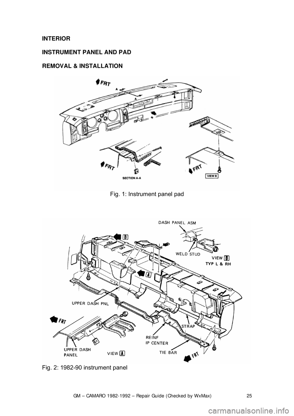
INSTRUMENT PANEL AND PAD
REMOVAL & INSTALLATION
Fig. 1: Instrument panel pad
Fig. 2: 1982-90 instrument panel
Page 26 of 875

GM – CAMARO 1982-1992 – Repair Guide (Checked by WxMax) 26
Fig. 3: 1991-92 instrument panel
CAUTION - The 1991-92 vehicles are equipped with an Air Bag system. Proper
disarming of the system is necessary before proceeding with any disassembly
or repairs to the steering column, das h or electrical system or possible
deployment of the air bag might occur. Refer to Suspension & Steering for
disarming procedure.
1. Properly disable t he SIR air bag system, if equipped. Disconnect the
negative battery cable.
2. Remove the center console.
3. Remove the screws attaching the in strument panel pad to the instrument
panel.
4. Remove the daytime running light sens or electrical connector, if equipped.
5. Remove the instrument panel pad.
6. Remove the instrument panel sound insulators.
7. Remove the knee bolster and bracket.
8. Remove the instrument panel cluster.
9. Remove the steering column retaining nuts and lower the column.
10. Remove the upper and lower instrument panel to cowl screws.
11. Disconnect and remove the electric al harness at the cowl connector and
under dash panel.
12. Remove the instrument panel assembly.
To install:
13. Install the instru ment panel assembly.
14. Install the electrical harness at the cowl connector and under dash panel.
15. Install the upper and lower inst rument panel to cowl screws.
16. Install the steering column retaining nuts.
17. Install the instru ment panel cluster.
18. Install the knee bolster and bracket.
Page 27 of 875

GM – CAMARO 1982-1992 – Repair Guide (Checked by WxMax) 27
19. Install the instrument panel sound insulators.
20. Install the inst
rument panel pad.
21. Install the daytime running light sensor electrical connector, if equipped.
22. Install the screws attaching the in strument panel pad to the instrument
panel.
23. Install the center console.
24. Properly arm the SIR air bag syste m, if equipped. Disconnect the negative
battery cable.
DOOR PANELS
REMOVAL & INSTALLATION
Fig. 1: Armrest and pull handle
Page 133 of 875

GM – CAMARO 1982-1992 – Repair Guide (Checked by WxMax) 133
WIRING & HARNESSES
The average vehicle contains meters
and meters of wiring, with hundreds of
individual connections. To protect the many wires from damage and to keep
them from becoming a confusing tangl e, they are organized into bundles,
enclosed in plastic or taped together and called wiring harnesses. Different
harnesses serve different parts of the vehi cle. Individual wires are color coded
to help trace them through a harness wher e sections are hidden from view.
Automotive wiring or circuit conductors can be either single strand wire, multi-
strand wire or printed circui try. Single strand wire has a solid metal core and is
usually used inside such components as alternators, motors, relays and other
devices. Multi-strand wire has a core made of many small strands of wire
twisted together into a single conductor. Most of the wiring in an automotive
electrical system is made up of multi-strand wire, either as a single conductor or
grouped together in a harness. All wiring is color coded on the insulator, either
as a solid color or as a colored wire wit h an identification stripe. A printed circuit
is a thin film of copper or other conducto r that is printed on an insulator backing.
Occasionally, a printed circuit is sandwic hed between two sheets of plastic for
more protection and flexibility. A comp lete printed circuit, consisting of
conductors, insulating material and connec tors for lamps or other components
is called a printed circuit board. Printed ci rcuitry is used in place of individual
wires or harnesses in places where space is limit ed, such as behind instrument
panels.
Since automotive electrical systems are very sensitive to changes in resistance,
the selection of properly sized wires is critical when systems are repaired. A
loose or corroded connection or a replacem ent wire that is too small for the
circuit will add extra resistance and an addi tional voltage drop to the circuit.
The wire gauge number is an expression of the cross-section area of the
conductor. Vehicles from countries that use the metric system will typically
describe the wire size as its cross-secti onal area in square millimeters. In this
method, the larger the wire, the gr eater the number. Another common system
for expressing wire size is the Americ an Wire Gauge (AWG) system. As gauge
number increases, area decreases and the wire becomes smaller. An 18 gauge
wire is smaller than a 4 gauge wire. A wire with a higher gauge number will
carry less current than a wire with a lower gauge number. Gauge wire size
refers to the size of the strands of the conductor, not the size of the complete
wire with insulator. It is possi ble, therefore, to have two wires of the same gauge
with different diameters because one may hav e thicker insulation than the other.
It is essential to understand how a circuit works before trying to figure out why it
doesn't. An electrical schematic shows the electrical current paths when a
circuit is operating proper ly. Schematics break the enti re electrical system down
into individual circuits. In a schematic, usually no attempt is made to represent
wiring and components as they physically appear on the vehicle; switches and
other components are shown as simply as possible. Face views of harness
connectors show the cavity or terminal lo cations in all multi-pin connectors to
help locate test points.
Page 146 of 875

GM – CAMARO 1982-1992 – Repair Guide (Checked by WxMax) 146
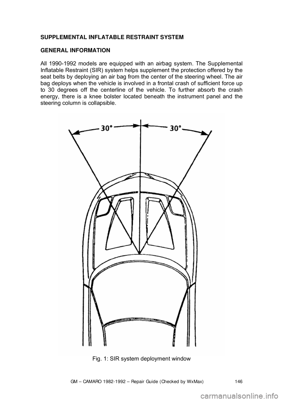
SUPPLEMENTAL INFLATABLE RESTRAINT SYSTEM
GENERAL INFORMATION
All 1990-1992 models are equi
pped with an airbag system. The Supplemental
Inflatable Restraint (SIR) syst em helps supplement the protection offered by the
seat belts by deploying an ai r bag from the center of the steering wheel. The air
bag deploys when the vehicle is involved in a frontal crash of sufficient force up
to 30 degrees off the center line of the vehicle. To further absorb the crash
energy, there is a knee bolster located beneath the instrument panel and the
steering column is collapsible.
Fig. 1: SIR system deployment window
Page 154 of 875

GM – CAMARO 1982-1992 – Repair Guide (Checked by WxMax) 154
HEATER CORE
REMOVAL & INSTALLATION
CAUTION - When draining the coolant, keep in mind that cats and dogs are
attracted by the ethylene gl ycol antifreeze, and are quite likely to drink any that
is left in an uncovered container or in puddles on the ground. This will prove
fatal in sufficient quantity. Always drai n the coolant into a sealable container.
Coolant should be reused unless it is contaminated or several years old.
1. Drain the cooling system.
2. Remove both heater hoses.
3. Remove the lower right hush panel.
4. Remove the lower right instru ment panel and the ESC module if
necessary.
5. Remove the lower right in strument panel-to-cowl screw.
6. Remove the heater case screws.
The upper left screw may be reached with a long socket extension. Carefully lift
the lower right corner of the instrument panel to align the extension.
7. Remove the case cover.
8. Remove the support plate and baffle screws.
9. Remove the heater core and ba ffle plate from the housing.
To install: 10. Position the heater core and baffle plate into the housing.
11. Install the support plate and baffle screws.
12. Install the case cover.
13. Install the heater case screws.
14. Install the lower right in strument panel-to-cowl screw.
15. Install the lower right instrument panel and the ESC module if necessary.
16. Install the lower right hush panel.
17. Install both heater hoses.
18. Fill the cooling system and check for leaks.
Fig. 1: Heater module assembly
Page 160 of 875

GM – CAMARO 1982-1992 – Repair Guide (Checked by WxMax) 160
damage, and legal considerations (such as t
he fact that it is a federal crime to
vent refrigerant into the atmosphere), dictate that the A/C components on your
vehicle should be serviced only by a Motor Vehicle Air Conditioning (MVAC)
trained, and EPA certified aut omotive technician.
If your vehicle's A/C system uses R-12 re frigerant and is in need of recharging,
the A/C system can be c onverted over to R-134a refrigerant (less
environmentally harmful and expensive). Refer to General Information &
Maintenance for additional information on R- 12 to R-134a conversions, and for
additional considerations dealing with your vehicle's A/C system.
CONTROL CABLES
REMOVAL & INSTALLATION
Some of the following cables will not be used on all models and model years.
Left and Right Air Vent Cables 1. Remove the left and right sound insulators.
2. Remove the screws attaching the cabl es to the steering column cover.
3. Disengage the cable clamps at the vent ducts.
4. Disengage the Z-shaped c able ends from the vent valve levers.
5. Remove the air vent cables notin g their positions for installation.
To install: 6. Place the cables in posi tion under the instrument panel.
7. Engage the Z-shaped cable ends to the vent valve levers.
8. Snap the cable clamps into the slot of the bracket formed on the vent
ducts.
9. Attach the air vent cables at the steering column cover.
10. Install the sound insulators and test cable operation.
Fig. 1: Cable attachment at the steering column cover
Page 181 of 875

GM – CAMARO 1982-1992 – Repair Guide (Checked by WxMax) 181
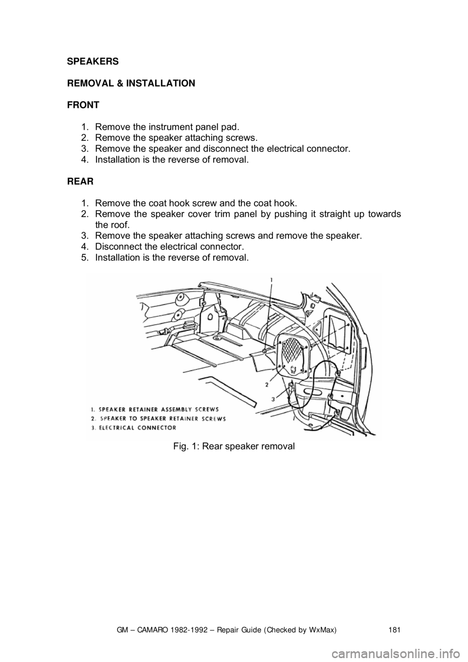
SPEAKERS
REMOVAL & INSTALLATION
FRONT
1. Remove the instrument panel pad.
2. Remove the speaker attaching screws.
3. Remove the speaker and disconnect the electrical connector.
4. Installation is the reverse of removal.
REAR 1. Remove the coat hook screw and the coat hook.
2. Remove the speaker cover trim panel by pushing it straight up towards
the roof.
3. Remove the speaker attaching screws and remove the speaker.
4. Disconnect the electrical connector.
5. Installation is the reverse of removal.
Fig. 1: Rear speaker removal