Page 797 of 875

GM – CAMARO 1982-1992 – Repair Guide (Checked by WxMax) 797
The cooling system should be drained, th
oroughly flushed and refilled at least
every 30,000 miles or 24 months. This operation should be done with the \
engine cold.
1. Drain the cooling system as de scribed earlier in this section.
2. Fill the cooling system with warm water and start the engine. Run the
engine until normal operating temperature is reached.
3. At this point, turn the engine o ff and again drain the cooling system.
4. Repeat this procedure until the flui d draining from the system is nearly
colorless.
5. Remove, empty and reinstall the coolant recovery reservoir assembly.
6. Fill the cooling system with a 50/50 mixture of ethylene glycol antifreeze,
as outlined in the prev ious procedure.
BRAKE MASTER CYLINDER
FLUID RECOMMENDATIONS
When adding or replacing the brake fluid, always use a top quality fluid, such as
Delco Supreme II or equivalent DOT-3 flui d. DO NOT allow the master cylinder
reservoir to remain open for long periods of time; brake fluid absorbs moisture
from the air, reducing it s effectiveness and causing corrosion in the lines.
Avoid spilling brake fluid on any of the vehicle's painted surfaces, wiring cables
or electrical connections. Brake fl uid will damage paint and electrical
connections. If any fluid is spilled on t he vehicle, flush with water to lessen
damage.
LEVEL CHECK
Fig. 1: Check master cylinder fluid leve l against indicator on side of reservoir.
Fluid level should not be below MIN marking on reservoir.
Page 849 of 875

GM – CAMARO 1982-1992 – Repair Guide (Checked by WxMax) 849
2. Loosen the screws and lo
cknuts from the back of the steering wheel
using a suitable Torx® driver or equi valent, until the inflator module can
be released from the steering wheel. Remove the inflator module from
the steering wheel.
CAUTION - When carrying a live inflator modul e, ensure the bag and trim cover
are pointed away from the body. In ca se of an accidental deployment, the bag
will then deploy with minima l chance of injury. When placing a live inflator
module on a bench or other surface, a lways place the bag and trim cover up,
away from the surface. This is necessa ry so a free space is provided to allow
the air bag to expand in the unlikely event of accidental deployment. Otherwise,
personal injury may result. Also, never carry the inflator module by the wires or
connector on the underside of the module.
4. Disconnect the coil assembly connec tor and CPA clip from the inflator
module terminal.
5. Remove the steering wheel locking nut.
6. Using a suitable pulle r, remove the steering wheel and disconnect the
horn contact. When attaching the steer ing wheel puller, use care to
prevent threading the side screws into the coil assembly and damaging
the coil assembly.
To install: 7. Route the coil assembly connec tor through the steering wheel.
8. Connect the horn contact and install the steering wheel. When installing
the steering wheel, ali gn the block tooth on the steering wheel with the
block tooth on the steering shaft within 1 female serration.
9. Install the steering wheel locking nu t. Tighten the nut to 31 ft. lbs. (42
Nm).
10. Connect the coil assembly connector and CPA clip to the inflator module
terminal.
11. Install the inflator module. Ensu re the wiring is not exposed or trapped
between the inflator modul e and the steering wheel. Tighten the inflator
module screws to 25 inch lbs. (2.8 Nm).
12. Connect the negative battery cable.
13. Enable the SIR system as follows: a. Connect the yellow 2-way SIR harness connector to base of the steering column and CPA.
b. Install the left sound insulator.
c. Install the SIR fuse in the fuse block.
d. Turn the ignition switch to the RUN position and verify that the
inflatable restraint indicator fl ashes 7-9 times and then turns OFF.
If the indicator does not respond as stated, a problem within the
SIR system is indicated.
Page 851 of 875

GM – CAMARO 1982-1992 – Repair Guide (Checked by WxMax) 851
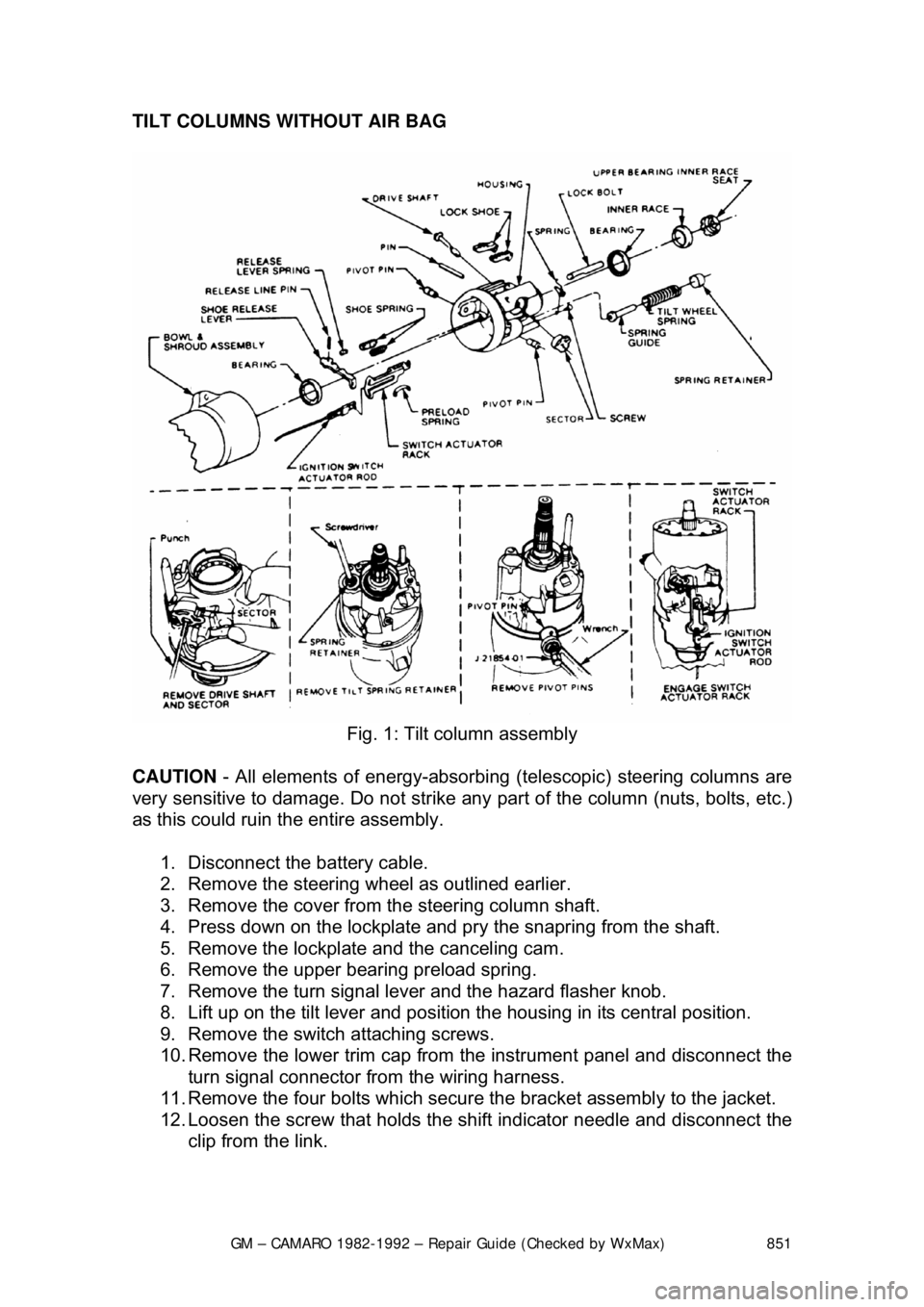
TILT COLUMNS WITHOUT AIR BAG
Fig. 1: Tilt column assembly
CAUTION - All elements of energy -absorbing (telescopic) steering columns are
very sensitive to damage. Do not strike any part of the column (nuts, bolts, etc.)
as this could ruin the entire assembly.
1. Disconnect the battery cable.
2. Remove the steering w heel as outlined earlier.
3. Remove the cover from the steering column shaft.
4. Press down on the lockplate and pr y the snapring from the shaft.
5. Remove the lockplate and the canceling cam.
6. Remove the upper bearing preload spring.
7. Remove the turn signal lever and the hazard flasher knob.
8. Lift up on the tilt lever and position the housing in its central position.
9. Remove the switch attaching screws.
10. Remove the lower trim cap from the instrument panel and disconnect the
turn signal connector from the wiring harness.
11. Remove the four bolts which secure the bracket assembly to the jacket.
12. Loosen the screw that holds the sh ift indicator needle and disconnect the
clip from the link.
Page 852 of 875

GM – CAMARO 1982-1992 – Repair Guide (Checked by WxMax) 852
13. Remove the two nuts fr
om the column support bracket while holding the
column in position. Remove the br acket assembly and wire protector
from the wiring, then l oosely install the support column bracket.
14. Tape the turn signal wires at the c onnector to keep them fit and parallel.
15. Carefully remove the turn signal switch and wiring from the column.
To install: 16. Carefully install the turn signal switch and wiring into the column.
17. Remove the tape from the turn signal wires.
18. Install the wire protecto r and, while holding the colu mn in position, install
the two nuts to the colu mn support bracket.
19. Connect the clip to the link and ti ghten the screw that holds the shift
indicator needle.
20. Install the four bolts which secure the bracket assembly to the jacket.
21. Connect the turn signal connector to the wiring harness and install the
lower trim cap to the instrument panel.
22. Install the switch attaching screws.
23. Install the turn signal lever and the hazard flasher knob.
24. Install the upper bear ing preload spring.
25. Install the lockplate and the canceling cam.
26. Press down on the lockplate and inst all the snapring to the shaft using a
new snapring.
27. Install the cover to t he steering column shaft.
28. Install the steering wheel.
29. Connect the battery cable.
Page 853 of 875

GM – CAMARO 1982-1992 – Repair Guide (Checked by WxMax) 853
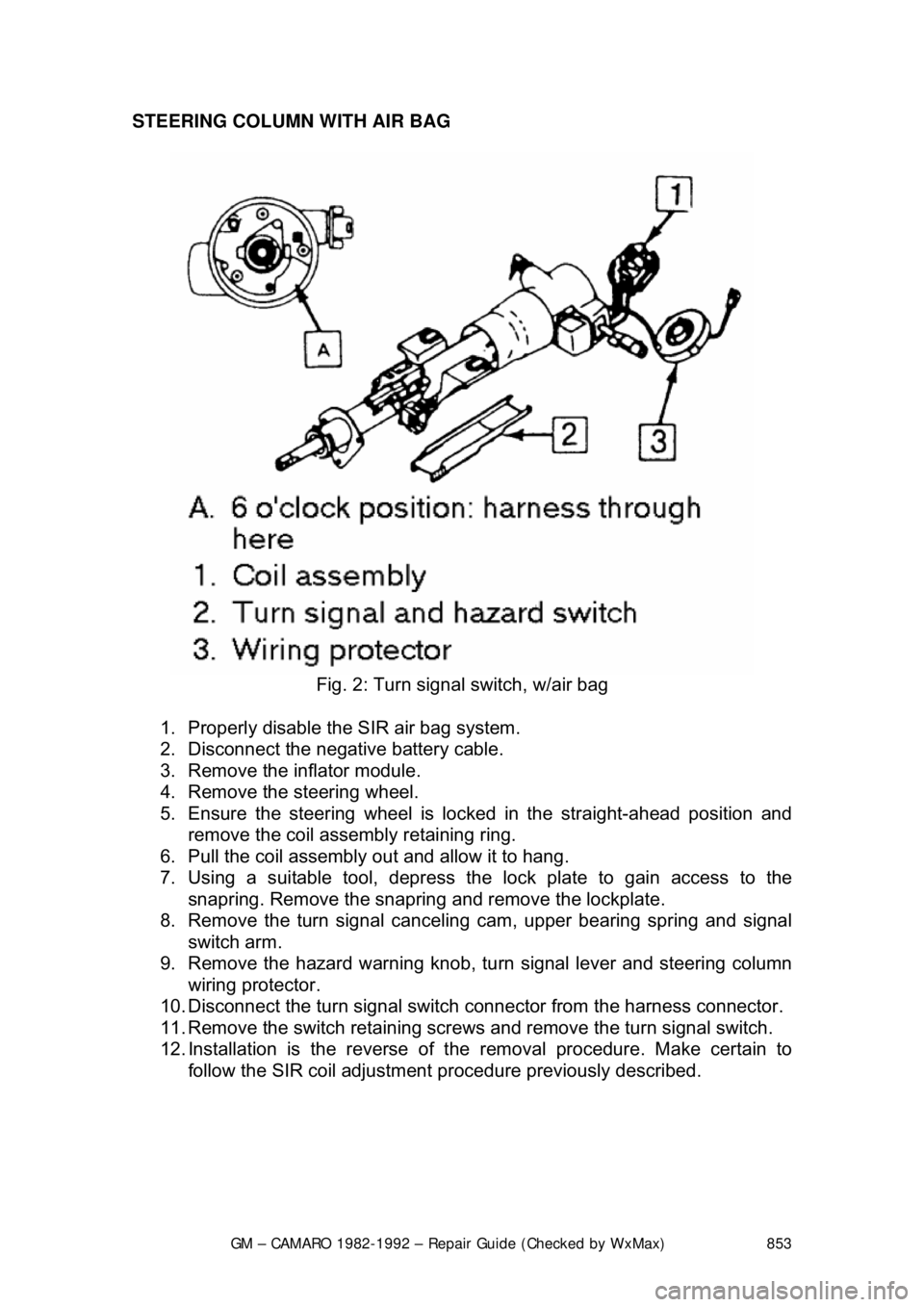
STEERING COLUMN WITH AIR BAG
Fig. 2: Turn signal switch, w/air bag
1. Properly disable the SIR air bag system.
2. Disconnect the negative battery cable.
3. Remove the inflator module.
4. Remove the steering wheel.
5. Ensure the steering wheel is locked in the straight-ahead position and
remove the coil assembly retaining ring.
6. Pull the coil assembly out and allow it to hang.
7. Using a suitable tool, depress the lock plate to gain access to the
snapring. Remove the snapring and remove the lockplate.
8. Remove the turn signal cancelin g cam, upper bearing spring and signal
switch arm.
9. Remove the hazard warning knob, tu rn signal lever and steering column
wiring protector.
10. Disconnect the turn signal switch connector from the harness connector.
11. Remove the switch retaining screws and remove the turn signal switch.
12. Installation is the reverse of t he removal procedure. Make certain to
follow the SIR coil adjustment pr ocedure previously described.