1982 CHEVROLET CAMARO wiring
[x] Cancel search: wiringPage 590 of 875

GM – CAMARO 1982-1992 – Repair Guide (Checked by WxMax) 590
REMOVAL & INSTALLATION
1. Disconnect the negative battery cable.
2. Disconnect the TPS electrical wiring.
3. Remove the mounting screws.
4. Remove the TPS and, if equipped, s ensor seal from the throttle body.
To install: 5. Place the TPS in positi on. Align the TPS lever with the sensor drive lever
on the throttle body.
6. Install the TPS mounting screws.
7. Connect the electrical wiring.
8. Connect the negative battery cable.
Fig. 1: Exploded view of a common TPS assembly
MASS AIR FLOW (MAF) SENSOR
OPERATION
The Mass Air Flow (MAF) sensor, found on some fuel injected engines,
measures the amount of air passing through it. The ECM uses this information
to determine the operating cond ition of the engine, to control fuel delivery. A
large quantity of air indicates acceleration, while a small quantity indicates
deceleration or idle.
The MAF sensor used on these vehicles is of the hot-wire type. Current is
supplied to the sensing wire to maintain a calibrated temperature, and as air
flow increases or decreases the current will vary. This varying current is directly
proportional to air mass.
Page 593 of 875

GM – CAMARO 1982-1992 – Repair Guide (Checked by WxMax) 593
REMOVAL & INSTALLATION
1. Disconnect the negative battery cable.
2. Drain the engine coolant.
3. Raise and properly support the vehicle.
4. Disconnect the knock sensor wiring harness.
5. Remove the knock sensor from the engine block.
CAUTION - The knock sensor is mounted in the engine block cooling passage.
Engine coolant in the block will dr ain when the sensor is removed.
6. Installation is the reverse of remova l. Tighten the sensor to 14 ft. lbs (19
Nm).
VEHICLE SPEED SENSOR (VSS)
OPERATION
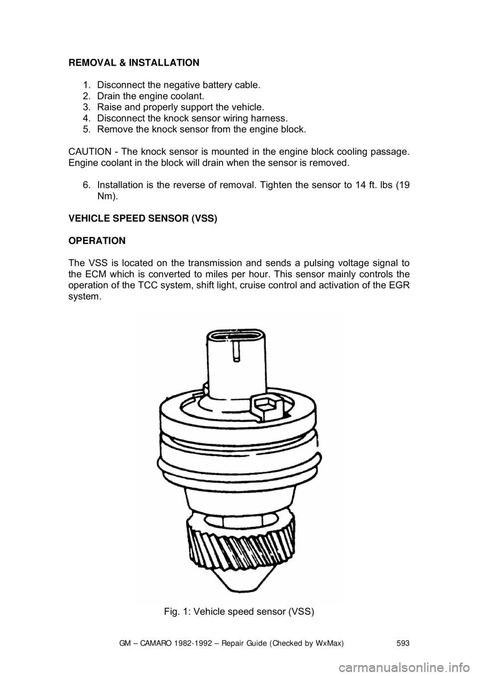
The VSS is located on the transmission and sends a pulsing voltage signal to
the ECM which is converted to miles per hour. This sensor mainly controls the
operation of the TCC system, shift light, cr uise control and activation of the EGR
system.
Fig. 1: Vehicle speed sensor (VSS)
Page 594 of 875

GM – CAMARO 1982-1992 – Repair Guide (Checked by WxMax) 594
REMOVAL & INSTALLATION
1. Disconnect the negative battery cable.
2. Raise and safely support the vehicle.
3. Disconnect the VSS electrical wiring.
4. Remove the retaining bolt.
5. Have a clean container to catch the transmission fluid and remove the
VSS.
6. Remove and discard the O-ring.
To install: 7. Lubricate a new O-ring with a thin f ilm of transmission fluid. Install the O-
ring and VSS.
8. Install the retaining bolt.
9. Connect the electrical wiring.
10. Lower the vehicle.
11. Connect the negative battery cable.
12. Refill transmission to proper level.
TROUBLE CODES
SELF DIAGNOSTICS
READING CODES
The following procedure applies to mode ls with the 12 pin diagnostic connector
only.
1. Turn the ignition switch OFF. Locate the Assembly Line Diagnostic Link
(ALDL), usually under the instrument panel. It may be within a plastic
cover or housing labeled DIAGNOSTIC CONNECTOR. This link is used
to communicate with the ECM.
2. Use a small jumper wire to connect Terminal B of the ALDL to Terminal
A. As the ALDL connector is viewed from the front, Terminal A is on the
extreme right of the upper row; Terminal B is second from the right on
the upper row.
3. After the terminals are connected, turn the ignition switch to the ON
position but do not start the engine. T he dash warning lamp should begin
to flash Code 12. The code will disp lay as one flash, a pause and two
flashes. Code 12 is not a fault code. It is used as a system
acknowledgment or handshake code; its presence indicates that the
ECM can communicate as requested. Code 12 is used to begin every
diagnostic sequence.
4. After Code 12 has been transmitted 3 times, the fault codes, if any, will
each be flashed in the same manner th ree times. The codes are stored
and transmitted in numeric order from lowest to highest.
The order of codes in the memory does not indicate the order of occurrence.
Page 595 of 875

GM – CAMARO 1982-1992 – Repair Guide (Checked by WxMax) 595
5. If one or more codes are stored,
record them. At the end of the
procedure, perform a visual and physical check of each system.
6. Switch the ignition OFF when finished with code retrieval.
Fig. 1: Diagnostic connector lo cation shown with a 12 pin connector
VISUAL AND PHYSICAL UNDERHOOD INSPECTION
A detailed examinatio n of connectors, wiring and va cuum hoses can often lead
to a repair without further diagnosis. This step relies on the skill of the
technician performing it; a careful inspec tor will check the undersides of hoses
as well as the integrity of hard-to-reac h hoses blocked by the air cleaner or
other component. Wiring should be check ed carefully for any sign of strain,
burning, crimping, or terminal pull-out from a connector. Checking connectors at
components or in harnesses is required; usually, pushing them together will
reveal a loose fit. It is important to note that the fault code indicates a fault or
loss of signal within that system, not necessarily the specific component. Due to
the intricacy of the systems and the spec ial testing equipment required, it is
Page 633 of 875

GM – CAMARO 1982-1992 – Repair Guide (Checked by WxMax) 633
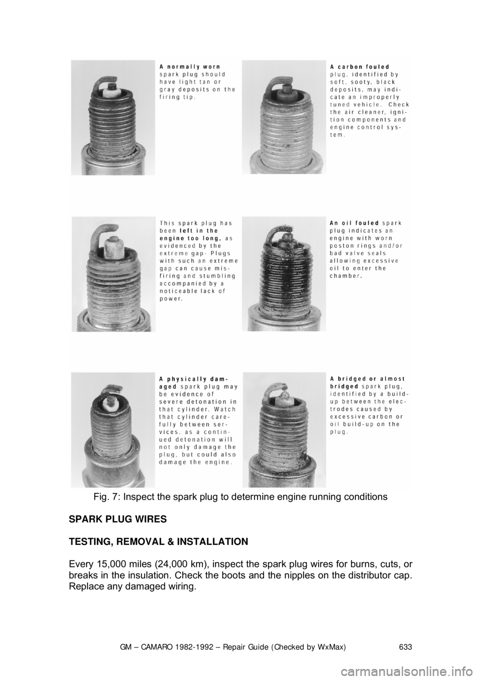
Fig. 7: Inspect the spark plug to determine engine running conditions
SPARK PLUG WIRES
TESTING, REMOVAL & INSTALLATION
Every 15,000 miles (24,000 km), inspect the spark plug wires for burns, cuts, or
breaks in the insulation. Check the boots and the nipples on the distributor cap.
Replace any damaged wiring.
Page 635 of 875

GM – CAMARO 1982-1992 – Repair Guide (Checked by WxMax) 635
FIRING ORDERS
To avoid confusion, remove and tag th
e spark plug wires one at a time, for
replacement.
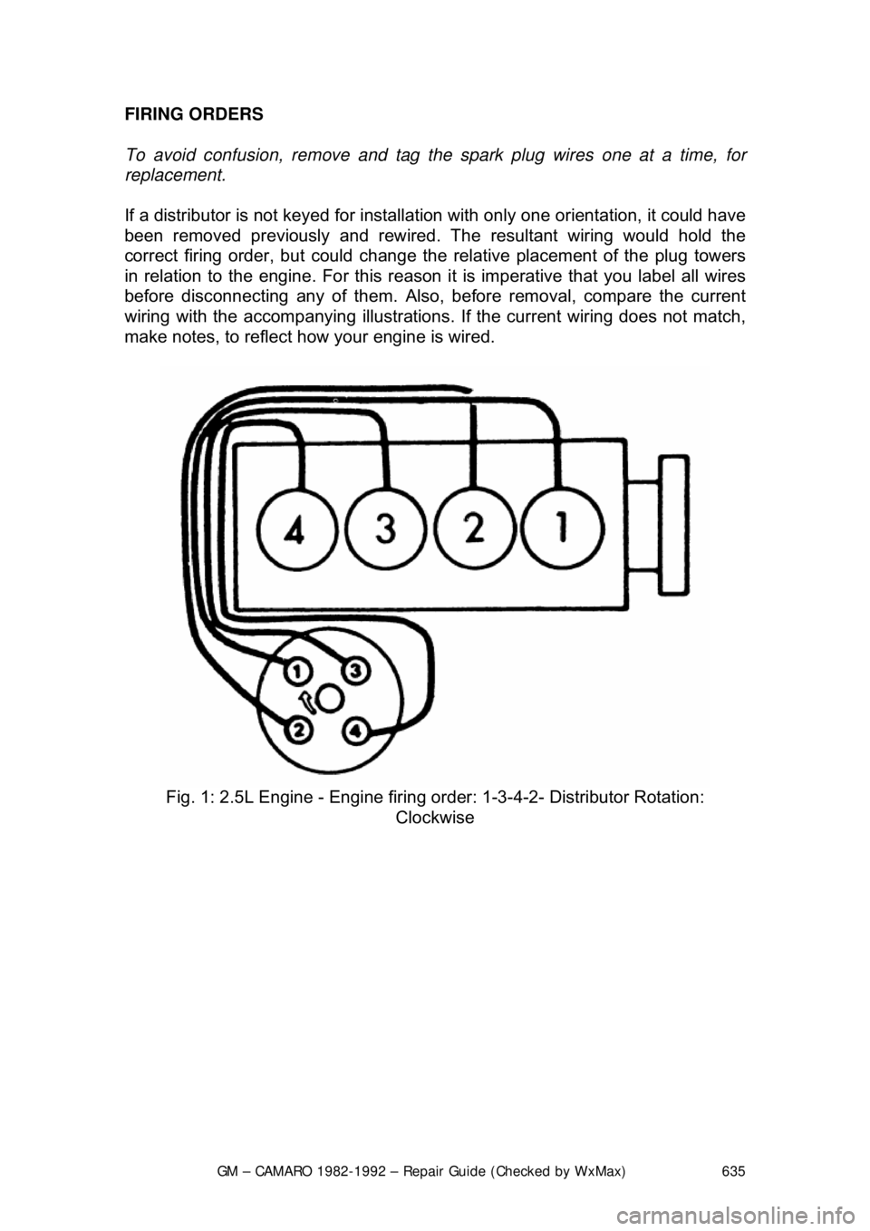
If a distributor is not keyed for installati on with only one orientation, it could have
been removed previously and rewired. Th e resultant wiring would hold the
correct firing order, but could change the relative placement of the plug towers
in relation to the engine. Fo r this reason it is imperative that you label all wires
before disconnecting any of them. Also, before removal, compare the current
wiring with the accompanying i llustrations. If the current wiring does not match,
make notes, to reflect how your engine is wired.
Fig. 1: 2.5L Engine - Engine firing or der: 1-3-4-2- Distributor Rotation:
Clockwise
Page 639 of 875

GM – CAMARO 1982-1992 – Repair Guide (Checked by WxMax) 639
In the HEI system, as in other electr
onic ignition systems, the breaker points
have been replaced wit h an electronic switch - a tr ansistor - which is located
within the ignition module. This switching transistor pe rforms the same function
the points did in a conventi onal ignition system; it simply turns the coil's primary
current on and off at the correct time. Essentially, electronic and conventional
ignition systems operate on t he same principle.
The module which houses the switching transistor is controlled (turned on and
off) by a magnetically gener ated impulse induced in the pickup coil. When the
teeth of the rotating timer align with t he teeth of the pole piece, the induced
voltage in the pickup coil signals the elec tronic module to open the coil primary
circuit. The primary current then decreases, and a high voltage is induced in the
ignition coil secondary windings, which is then directed through the rotor and
high voltage leads (spark plug wires) to fire the spark plugs.
In essence, the pickup coil module system simply replaces the conventional
breaker points and condenser. The condenser found within the distributor is for
radio suppression purposes only and has nothing to do with the ignition
process. The ignition module automatically controls the dwell period, increasing
it with increasing en gine speed. Since dwell is co ntrolled in this manner, it
cannot be adjusted. The module itse lf is non-adjustable/non-repairable and
must be replaced if found defective.
SYSTEM PRECAUTIONS
Before proceeding with troubleshooting, ta ke note of the following precautions:
TIMING LIGHT USE
Care should be exercised when connec ting a timing light or other pick-up
equipment. Do not force anything between the boots and wiring, or through the
silicone jacket. Connections should be made in parallel using an adapter.
Inductive pickup timing lights are the bes t kind to use with the ignition systems
covered by this information.
SPARK PLUG WIRES
The plug wires used with these systems are of a different construction than
conventional wires. When replacing them, make sure you get the correct wires,
since conventional wires will not carry the voltage. Also, handle the wires
carefully to avoid cracking or splitti ng them, and NEVER pierce the wires.
TACHOMETER USE
Not all tachometers will operate or indi cate correctly when used on an HEI or
C
3I system. While some tachometers ma y give a reading, this does not
necessarily mean the reading is correct. In addition, some tachometers hook up
differently from others. If you cannot fi gure out whether or not your tachometer
will work on your car, check with the tachometer manufacturer.
Page 640 of 875

GM – CAMARO 1982-1992 – Repair Guide (Checked by WxMax) 640
The tachometer terminal should never
be allowed to touch ground, as damage
to the computer control module and/or ignition coil assembly can result.
CONNECTORS
When disengaging connectors, do not use a screw driver or other tool to release
the locking tab, as this mi ght break the connector.
SYSTEM TESTERS
Instruments designed specific ally for testing HEI or C
3I systems are available
from several tool manufactur ers. Some of these will even test the module itself.
However, the tests given in the followin g section will require only an ohmmeter
and a voltmeter.
TESTING
The symptoms of a defective component within the HEI or C
3I system are
exactly the same as those you woul d encounter in a conventional system.
Some of these symptoms are:
• Hard or no starting
• Rough Idle
• Poor fuel economy
• Engine misses under load or while accelerating
PRELIMINARY CHECKS
If you suspect a problem in your igniti on system, there are certain preliminary
checks which you should carry out befor e you begin to check the electronic
portions of the system. First, it is extrem ely important to make sure the vehicle
battery is in a good state of charge. A defective or poorly charged battery will
cause the various components of the ignition system to read incorrectly when
they are being tested. Second, make su re all wiring connections are clean and
tight, not only at the battery, but also at the distributor cap (if so equipped),
ignition coil, camshaft and/or crankshaft sensors (if so equipped) and at the
control module.
Since the only difference between these ignition systems lies before the spark
plug wiring, it is important to check the secondary ig nition circuit first. If the
secondary circuit checks out properly (ther e is spark), then the engine condition
is probably not the fault of the ignition system. To check the secondary ignition
system, perform a simple spark test. Remove one of the plug wires and insert
some sort of extension in the plug socket. An old spark plug with the ground
electrode removed makes a good extension. Hold the wire and extension using
an insulated tool (NOT BY HAND) about
1/4 in. (6mm) away from the block and
crank the engine. If a normal spark occurs, then the problem is most likely not in
the ignition system. Check for fuel system problems, or fouled spark plugs.