1982 CHEVROLET CAMARO horn
[x] Cancel search: hornPage 11 of 875
GM – CAMARO 1982-1992 – Repair Guide (Checked by WxMax) 11
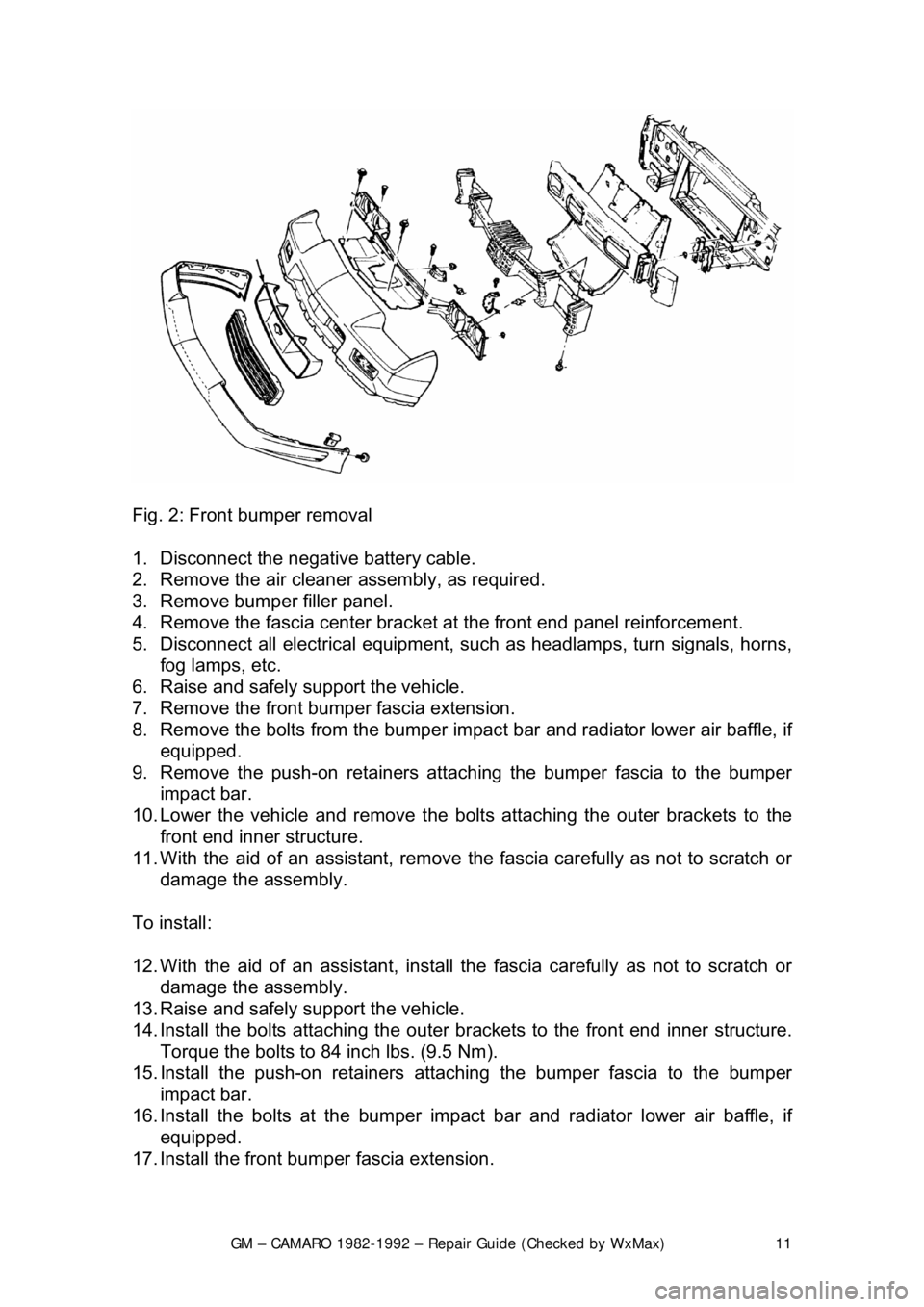
Fig. 2: Front bumper removal
1. Disconnect the negative battery cable.
2. Remove the air cleaner assembly, as required.
3. Remove bumper filler panel.
4. Remove the fascia center bracket at the front end panel reinforcement.
5. Disconnect all electrical equipment, su ch as headlamps, turn signals, horns,
fog lamps, etc.
6. Raise and safely support the vehicle.
7. Remove the front bumper fascia extension.
8. Remove the bolts from the bumper impac t bar and radiator lower air baffle, if
equipped.
9. Remove the push-on retainers attach ing the bumper fascia to the bumper
impact bar.
10. Lower the vehicle and remove the bolt s attaching the outer brackets to the
front end inner structure.
11. With the aid of an assistant, remove t he fascia carefully as not to scratch or
damage the assembly.
To install:
12. With the aid of an assistant, install t he fascia carefully as not to scratch or
damage the assembly.
13. Raise and safely support the vehicle.
14. Install the bolts attachi ng the outer brackets to the front end inner structure.
Torque the bolts to 84 inch lbs. (9.5 Nm).
15. Install the push-on retainers atta ching the bumper fascia to the bumper
impact bar.
16. Install the bolts at t he bumper impact bar and radiat or lower air baffle, if
equipped.
17. Install the front bum per fascia extension.
Page 12 of 875
GM – CAMARO 1982-1992 – Repair Guide (Checked by WxMax) 12
18. Connect all electrical equipment, such
as headlamps, turn signals, horns,
fog lamps, etc.
19. Install the fascia center bracket at the front end panel reinforcement.
20. Install bumper filler panel.
21. Install the air cleaner assembly, as required.
22. Connect the negative battery cable.
REAR
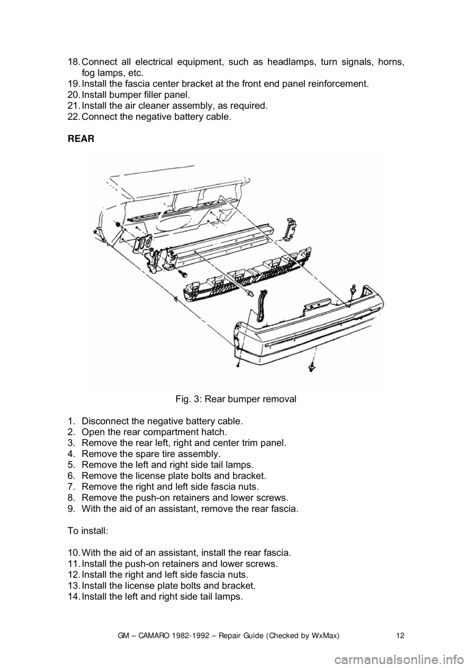
Fig. 3: Rear bumper removal
1. Disconnect the negative battery cable.
2. Open the rear compartment hatch.
3. Remove the rear left, ri ght and center trim panel.
4. Remove the spare tire assembly.
5. Remove the left and right side tail lamps.
6. Remove the license plate bolts and bracket.
7. Remove the right and left side fascia nuts.
8. Remove the push-on retainers and lower screws.
9. With the aid of an assistan t, remove the rear fascia.
To install:
10. With the aid of an assistan t, install the rear fascia.
11. Install the push-on retainers and lower screws.
12. Install the right and left side fascia nuts.
13. Install the license plate bolts and bracket.
14. Install the left and right side tail lamps.
Page 16 of 875

GM – CAMARO 1982-1992 – Repair Guide (Checked by WxMax) 16
8. Remove the front end bumper fa
scia-to-fender nuts and screws.
9. Remove the hood hinge-to-fender bolts.
10. Disconnect all electrical connections from horn, turn signal lamps, etc.
11. Remove the fender by sliding rearward and outward, at rear, with the aid of
an assistant. Place an old blanket over the fender as to avoid scratches or
dents.
To install:
12. Install the fender with the aid of an assistant. Plac e an old blanket over the
fender as to avoid scratches or dents.
13. Connect all electrical connections to the horn, turn signal lamps, etc.
14. Install the hood hinge-to-fender bolts.
15. Install the front end bumper fascia-to-fender nuts and screws.
16. Install the bolt at the support brace.
17. Install the lower front end panel deflector-to-fender bolts.
18. Install the rocker panel molding.
19. Install the lower fender bol ts and inner wheel house panel.
20. Install the hood.
21. Disconnect the negative battery cable. Align the fender and hood as
necessary, placing existing shims in original positions.
Page 132 of 875

GM – CAMARO 1982-1992 – Repair Guide (Checked by WxMax) 132
Some electrical components which require
a large amount of current to operate
use a special switch called a relay. Sinc e these circuits carry a large amount of
current, the thickness of the wire in the ci rcuit is also greater. If this large wire
were connected from the load to the c ontrol switch, the switch would have to
carry the high amperage load and the fair ing or dash would be twice as large to
accommodate the increased size of t he wiring harness. To prevent these
problems, a relay is used.
Relays are composed of a coil and a se t of contacts. When the coil has a
current passed though it, a magnetic fiel d is formed and this field causes the
contacts to move together, completing the circuit. Most relays are normally
open, preventing current from passing thr ough the circuit, but they can take any
electrical form depending on th e job they are intended to do. Relays can be
considered "remote control switches." They allow a smaller current to operate
devices that require higher amperages. W hen a small current operates the coil,
a larger current is allo wed to pass by the contacts. Some common circuits
which may use relays are the horn, headlight s, starter, electric fuel pump and
other high draw circuits.
Fig. 3: Relays are composed of a coil and a switch. These two components are
linked together so that w hen one operates, the other operat es at the same time.
The large wires in the circuit are connect ed from the battery to one side of the
relay switch (B+) and from the opposite side of the re lay switch to the load
(component). Smaller wires are connected from the relay coil to the control
switch for the circuit and from the opposite side of the relay coil to ground
LOAD
Every electrical circuit must include a "load" (something to use the electricity
coming from the source). Without this l oad, the battery would attempt to deliver
its entire power supply from one pole to another. This is called a "short circuit."
All this electricity would take a short cut to ground and cause a great amount of
damage to other components in the circui t by developing a tremendous amount
of heat. This condition could develop suffici ent heat to melt the insulation on all
the surrounding wires and reduce a multiple wire cable to a lump of plastic and
copper.
Page 670 of 875

GM – CAMARO 1982-1992 – Repair Guide (Checked by WxMax) 670
the idle speed or mixture,
adjust the idle and mixture again when you are
finished.
Before you make any carburetor adjustment s make sure that the engine is in
tune. Many problems which are thought to be carburetor related can be traced
to an engine which is simply out-of-tune. Any trouble in these areas will have
symptoms like those of carburetor problems.
ADJUSTMENTS
FAST IDLE
ROCHESTER E2SE 1. Refer to the emission label and pr epare the vehicle for adjustment.
2. Place the fast idle screw on the highest step of the fast idle cam.
3. Turn the fast idle screw to obtain the fast idle speed.
ROCHESTER E4ME AND E4MC
The fast idle adjustment must be perform ed according to the directions of the
emissions label.
FLOAT AND FUEL LEVEL
ROCHESTER E2SE
1. Remove the air horn and gasket.
2. While holding the retainer in place, push the float down lightly against the
needle.
3. Place a measuring gauge on the float at the farthest point from the float
hinge.
4. To adjust, remove the float and bend the arm up or down. Also check the
float alignment.
5. Install the air horn and gasket.
Page 672 of 875
GM – CAMARO 1982-1992 – Repair Guide (Checked by WxMax) 672
ROCHESTER E4ME AND E4MC
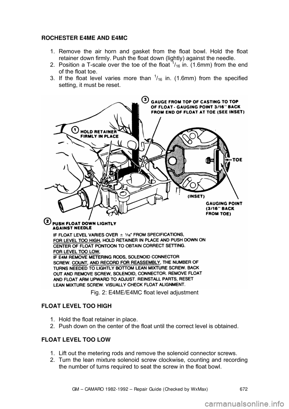
1. Remove the air horn and gasket from the float bowl. Hold the float retainer down firmly. Push the float down (lightly) against the needle.
2. Position a T-scale ov er the toe of the float
1/16 in. (1.6mm) from the end
of the float toe.
3. If the float level varies more than
1/16 in. (1.6mm) from the specified
setting, it must be reset.
Fig. 2: E4ME/E4MC float level adjustment
FLOAT LEVEL TOO HIGH 1. Hold the float retainer in place.
2. Push down on the center of the float until the correct level is obtained.
FLOAT LEVEL TOO LOW 1. Lift out the metering rods and remo ve the solenoid connector screws.
2. Turn the lean mixture solenoid screw clockwise, counting and recording
the number of turns required to seat the screw in the float bowl.
Page 687 of 875
GM – CAMARO 1982-1992 – Repair Guide (Checked by WxMax) 687
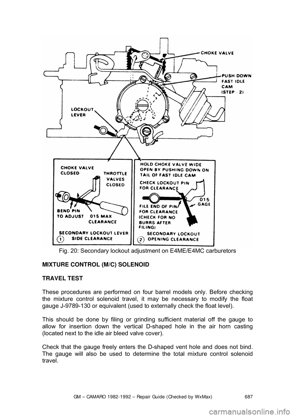
Fig. 20: Secondary lockout adjus tment on E4ME/E4MC carburetors
MIXTURE CONTROL (M/C) SOLENOID
TRAVEL TEST
These procedures are performed on four barrel models only. Before checking
the mixture control solenoid travel, it may be necessary to modify the float
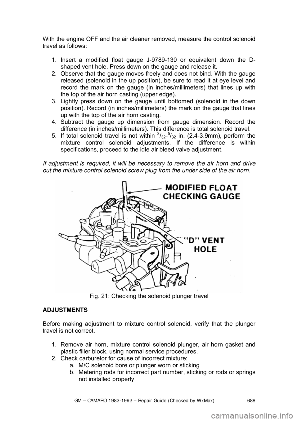
gauge J-9789-130 or equivalent (used to ex ternally check the float level).
This should be done by filing or grinding sufficient material off the gauge to
allow for insertion down the vertical D-shaped hole in the air horn casting
(located next to the idle air bleed valve cover).
Check that the gauge freely enters the D-shaped vent hole and does not bind.
The gauge will also be used to determine t he total mixture control solenoid
travel.
Page 688 of 875
GM – CAMARO 1982-1992 – Repair Guide (Checked by WxMax) 688
With the engine OFF and the air cleaner re
moved, measure the control solenoid
travel as follows:
1. Insert a modified float gauge J- 9789-130 or equivalent down the D-
shaped vent hole. Press down on the gauge and release it.
2. Observe that the gauge moves freel y and does not bind. With the gauge
released (solenoid in the up position), be sure to read it at eye level and
record the mark on the gauge (in inc hes/millimeters) that lines up with
the top of the air hor n casting (upper edge).
3. Lightly press down on the gauge until bottomed (solenoid in the down
position). Record (in inches/millimeters) the mark on the gauge that lines
up with the top of the air horn casting.
4. Subtract the gauge up dimension from gauge dimension. Record the
difference (in inches/millimet ers). This difference is total solenoid travel.
5. If total solenoid travel is not within
3/32-5/32 in. (2.4-3.9mm), perform the
mixture control solenoid adjustment s. If the difference is within
specifications, proceed to the id le air bleed valve adjustment.
If adjustment is required, it will be necessary to remove the air horn and drive
out the mixture control solenoid screw pl ug from the under side of the air horn.
Fig. 21: Checking the solenoid plunger travel
ADJUSTMENTS
Before making adjustment to mixture cont rol solenoid, verify that the plunger
travel is not correct.
1. Remove air horn, mixture control solenoid plunger, air horn gasket and
plastic filler block, using normal service procedures.
2. Check carburetor for caus e of incorrect mixture:
a. M/C solenoid bore or plunger worn or sticking
b. Metering rods for incorrect part number, sticking or rods or springs
not installed properly