1980 CHEVROLET CITATION high beam
[x] Cancel search: high beamPage 23 of 95
Downloaded from www.Manualslib.com manuals search engine • Off· You can turn off the engine without loc king the steering ,wheel and shirt control s o'n aut omatic tranSaxle models. or steering -wh eel only on
mariual transaxle models.
• Run· Normal operating position.
• Start -Cranks the engine:
If you have trouble turning the key to unlock the ignition. first be sure the key
i s pushed in all the way. Then try to turn the ste ering wheel as hard as you can
in the _di rec tion the Wheels are turned. At th e same time, turn the ignition key
with
as mu ch effort as you can apply with your ha nd. Do not try to use a tool
of any kind to
a_pply more force on 'the lock knob. as this could bre ak the kn.ob.
CAUTION: .on manual tranS8xle cars. if you need to turn off the engina while the car is moving. turn the key onlv to ".off." DO NOT press down on the key release lever while turning the ignition off. This will result in locking the steering wheel and If'S8 of steering control.
NOTICE: Do_.oot drive through . idle or park your vehicle over combustible materials. such as grass or lC!'aves. They could touch the hot exhaust system and Ignite.
Parking
When leaving your car unatte nded :
• Firml y appl y the park ing brake. Do n o t use th e tran saxle a 's a substitut e for (he parking brake.
• Mov e the automatic transaxle shift lever to "P"(Park) ("Rever se" for man ual
tran saxle ).
• 'Turn the key to "Lock ," On manualtransaxle cars, press,down the key release
lever a
nd turn the key to "Lock. "
•
Close all windows.
• Remove the key (the buzzer is designed to remind you).
• Lock ,,'n doors.
TURN SIGNAL AND MULTI-FUNCTION LEVER
The I urn signa l-lever on th e left side of the ste erin g column also co ntr ols headlight
l ow -beam
or high·beam. and the windshield wiper/washer .
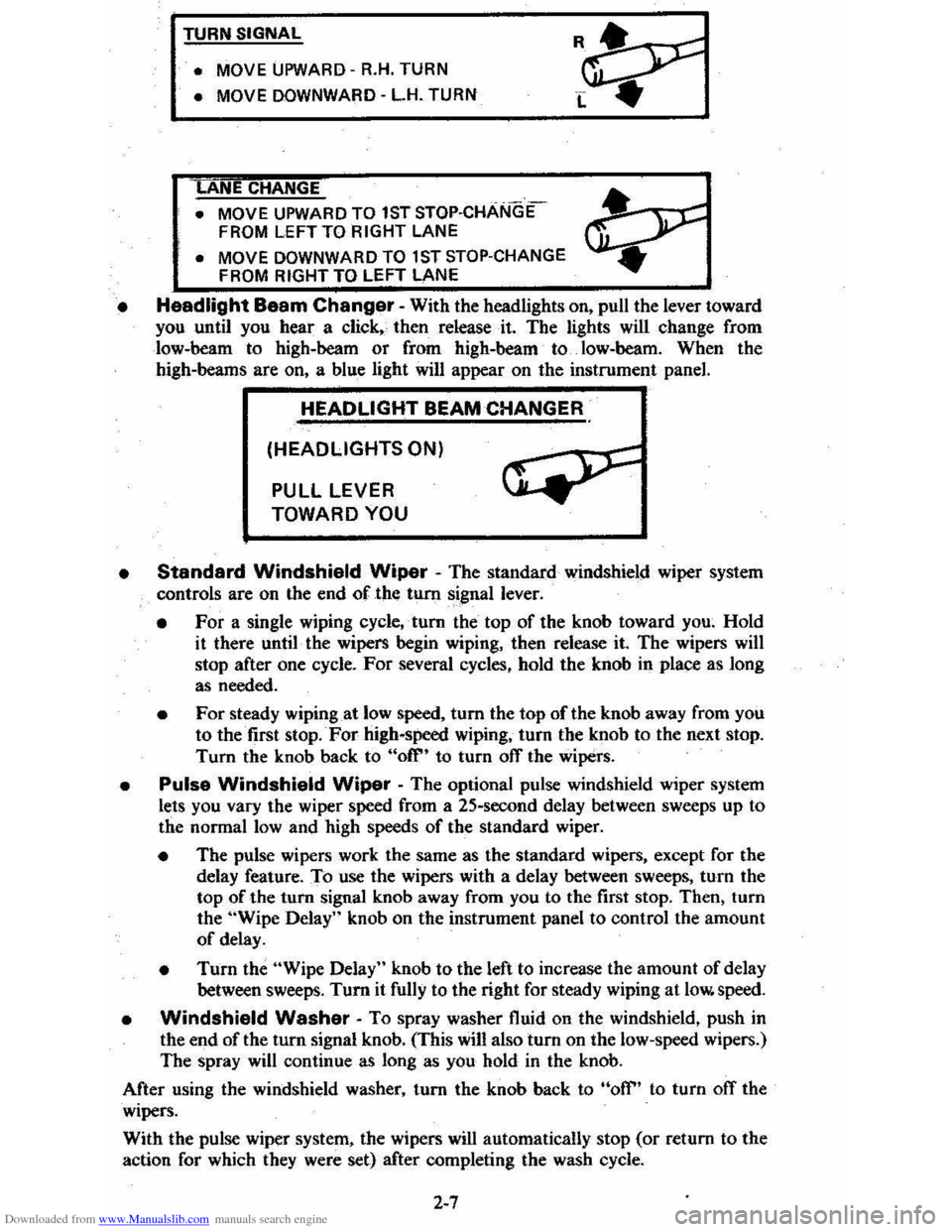
• Turn Signal -Move the lever up to t he second stop to signal a right tum.
Move it do wn 10 the seco nd stop to sig nal a left turn . When the turn is
compleled, the signal will cancel and the lever will return to' h o rizont al.
• Lane Change Signal. In some turns. such as ch an ging lanes, the steering wheel is not turned far enou gh 10 ca nce l th e turn signal. Fo r convenience.
you
can flash Ihe turn signal by moving the lever part way (to t-he first stop) and h olding it there. The lever will re turn to horizo ntal when 'You release it.
Tw o green lights_ o n the instrum ent panel are des igned to nas h 10 tell you that
th e front and rear turn
sign al light s are working. If the light stays on, but does
not flash, check for bur ned- out turn signal bulbs. If Ihe green light does not com e
all when yo u m ove the leve r. c _h ec k the fuse and indicator . bulb. However, iryou
ordered a ,tra iler towing optio n in which extra wiring waS added to attach the
trailer lighting, a different type
of flasher was installed . In this case , the gree n light will co ntinu e 10 flas h even if a turn sig nal bulb burns out. Therefore, you must
regularly look at the front and
rear turn signal light s 10 be sure they are working.
2-6
Page 24 of 95
Downloaded from www.Manualslib.com manuals search engine TURN SIGNAL
• MOVE
UPWARD -R.H. TURN
• MOVE DOWNWARD -L.H. TURN
ANE CHANGE
• MOVE UPWARD TO 1ST STOP·CHANGE
FROM LEFT TO RIGHT LANE
• MOVE DOWNWARD TO 1 ST STOP-CHANGE
FROM RIGHT TO LEFT LANE
• Headlight Baam Changer -With the headlights on, pull the lever toward you until you hear a click" then release· it. The lights will change from
low-beam to high-beam
or from high-beam to. low-heam. When the high-beams are on, a blue light will appear on the instrument panel.
HEADLIGHT BEAM CHANGER
(HEADLIGHTS ON)
PULL LEVER
TOWARD YOU
•
Standard Windshield Wiper - The standard windshield wiper system
controls are on the end of the tum signal lever.
• For a single wiping cycle,' tum the top of the knob toward you~ Hold
it there until· the wipers begin wiping, then release it. The wipers will stop after one cycle. For several cycles, hold the knob in place as long
as needed.
• For steady wiping at low speed, tum the top of the knob away from you to the first stop. For high-speed wiping, turn the knob to the next stop.
Turn the knob back to "ofr' to turn off the wipers.
• Pulse Windshield Wiper -The optional pulse windshield wiper system
lets you vary the wiper speed from a 25-second delay between sweeps up to
the normal
low and high speeds of the standard wiper.
• The pulse wipers work the same as the standard wipers, except for the
delay feature. To use the wipers with a delay between sweeps, turn the
top of the turn signal knob away from you to the first stop. Then, turn
the "Wipe Delay" knob on the instrument panel to control the amount
of delay.
• Turn the "Wipe Delay" knob to the left to increase the amount of delay
between sweeps. Tum it fully to the right for steady wiping at low. speed.
• Windshield Washer -To spray washer fluid on the windshield, push in the end of the tum signal knob. (This will also turn on the low-speed wipers.)
The spray will continue as long as you hold
in the knob.
After using the windshield washer, turn the knob back to
"off" to turn ofT the
wipers.
With the pulse wiper system, the wipers
will automatically stop (or return to the
action for which they were set) after completing the wash cycle.
2-7
Page 31 of 95
Downloaded from www.Manualslib.com manuals search engine CAUTION: Driving thr~gh water deep enough to wet the brakes may cause the brakes not to work as well. As 8 result the vehicle will not slow down at the usual
rate ; and it may pull to the right or left. After checking to the rear for other vehicle., apply the brakes lightly to check whether this has happened. To dry them quickly, lightly apply the brakes. At the-same time, k .. p a safe forward speed, with plenty of clear space ahead, to the rear, and to the side •. 00 this until the brakes return to normal.
The brake system warning light is covered in the "Instrument Panel" section.
Power Brakes
• If optional power assis t is lost because of a stalled engine or other reasons .
the brakes can normally still be applied with power assist at leas t two times
u sing reserv e power.
• Th e system is designed to bring the vehicle to a full stop on reserve power if the brake pedal is applied once and held down . However . the reserve power
is partly used up each time the brake pedal is applied and rele ased. Do not
pump the brakes when ,brake power assist has been lost, except when needed
to maintain steering control on slippery surfaces.
• Without power assist, the vehicle can still be stopped by pushing much harder
o n the brake pedal. However, the stopping distance may be longer. even
though the brakes themselves remain fully operational.
Self-Adjusting Brakes
• The brakes on this vehicle (exc,ept for the parking brake) are self-adjusting.
They have been design ed so
that periodic brake adjustment is not required.
• The drum brakes adjust themselves when the brakes are firml y applied while
the vehicle is moving backwards.
• The disc brakes adjust themselve s each time the brakes are used.
• If the brak e pedal goes down farther than nonnal. it may be due to a lack
of adjustment. To find out if this is the case, drive backward and forward
a few times , applying the brakes firmly when going each way.
• See yo ur dealer if pedal height does not return to normal, or if there is a rapid
increase in pedal travel, which could be a sign of other brake trouble .
• Also see your dealer if the parking brake needs adjustment' .
NOTICE: "Riding the brake" by resting your foot on the brake pedal when not intending to brake can cause overheated brakes. This can waar out the brake linings faster and damage the brakas thamselvas, 85 well 8S waste fuel.
DIMMER SWITCH
The dimmer switch that controls the headlight high/lo w beam is built into the
turn signal control. See the "Steering Column Controls" Section 2 of this manual.
PARKING BRAKE
• To set the parking brake, fully depress the foot pedal at the far left side.
• For better holding power, first press down the regular brake pedal with your
right foot. Then hold it while setting the parking brake with your lefl foo[.
•
To release the parking brake, pull the "Brake Release" handle located at the
lower left of the instrument panel.
• To help remind you. the brake system warning light is designed to come on if the parking brake control is not fully released and the ignition key is on.
2-14
Page 36 of 95
Downloaded from www.Manualslib.com manuals search engine Engine Temperature Gage
This gage indicat~cCX?lant temperature which will vary with air temperature and
operating condition~, The ignition must be on for accurate readings. Hard driving
or prolonged idling In very hot weather will cause the pointer to move beyond the center of the band; Should pointer move to the Red Zone, see "Engine Cooling
System" on page 3-3.
Oil Pressure Gage
The oil pressure gage indicates the pn;ssure at which oil is being delivered 10 the various parts of the engine requiring lubrication. Pressures registered by the gage
I11.!lY vary according to outside air temperatures or weight of oil being used. Oil
pressure of a cold engine ~ing operated at a given speed will be somewhat higher
than when the engine is at normal operating temperature at the same speed .
. Prolonged high speed operation on a hot day at the given speed will result in somewhat lower oil pressure readings. Readings of 30 to 40 psi (205 to 275 kPa)
mny
be considered normal during moderate road speeds of 35 to 40 mph (55 to
60 km/h) \\lith the engine at proper operating temperature. Gage readings which
are
consistently high or Im\l under these conditions may indicate lubrication system
When the engine is operating, the voltmeter indicates the electrical system voltage.
During minimum electrical load, the pointer will read to the right of the center.
As the electrical load is increased,
or in stop-and-go driving, the pointer will rotate
to the left. A meter reading continuously in
the left or right red zone indicates
an electrical system
failure .. Cause of the failure should be determined and corrected~
Light Switch
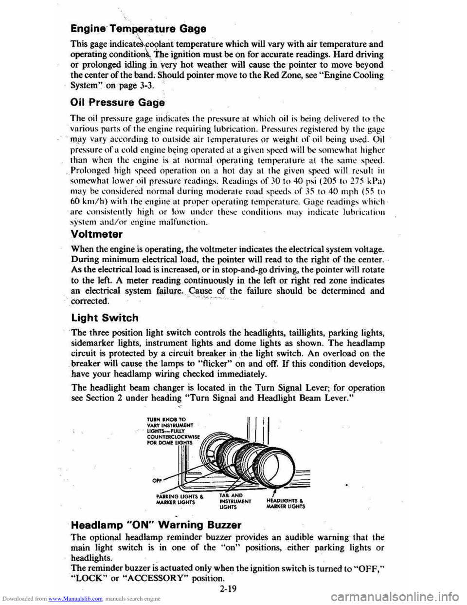
The three position light switch controls the headlights, taillights, parking lights,
sidemarker lights, instrument lights and dome lights as shown. The headlamp
circuit is protected by a circuit breaker in
the light switch. An overload on the
breaker will cause the lamps to "flicker" on and off. If this condition develops,
have your headlamp wiring checked immediately.
The headlight beam changer is located. in the
Turn Signal Lever; for operation
see Section 2 under heading "Tum Signal and Headlight Beam Lever."
TUIN KNOt TO VAr:t'INSTRUMENT lIGHTS_'UtLy COUNTERClOCKWISE RlR DOME
0"
MAltlCfIt LIGHTS , INSTRUMENT LIGHTS
Headlamp "ON" Warning Buzzer
The optional headlamp reminder buzzer provides an audible warning that the
main light switch is in one
of the "on" positions, either parking lights or
headlights.
The reminder buzzer
is actuated only when the ignition switch is turned to "OFF," "LOCK" or "ACCESSORY" position.
2-19
Page 85 of 95
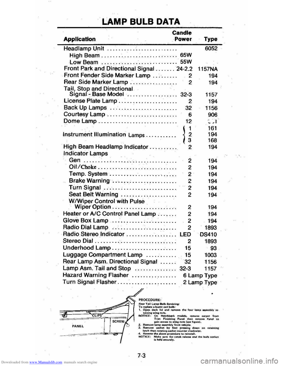
Downloaded from www.Manualslib.com manuals search engine LAMP BULB DATA
Application
Candle
Power
Headlamp Unit
.................. .
High Beam
........................... 65W
Low Beam ........................... 55W
Front park and Directional Signal ....... 24·2.2
Front Fender Side Marker Lamp .. , .. . .. . 2
Rear
Side Marker Lamp. . . . . . . . . . . . . . . . . 2
Tail, Stop and Directional Signal -Base Model , .........•....... 32-3
License
Plate Lamp ........• '" .. . . . . . . . . 2
Back Up Lamps
........................ 32
Courtesy
Lamp. . . . . . . . . . .. .. . .. . .. . .. . . 6
Dome
Lamp............................ 12
Instrument
Illumination Lamps .......... .
High Beam Headlamp
Indicator ......... .
Indicator Lamps
Gen
......... , ...................... .
Oil/Choke ......................••....
Temp. System .................. , .•...
Brake Warning ....•........•.....••..
Turn Signal ......................... .
Seat Belt Warning .................••.
WIWiper Control with Pulse
n 2
2
2
2
2
2
2
Type 6052
1157NA
194
194
1157 194
1156
906
~ ,I
161 194 168
194
194
194
194
194
194
194
Wiper
Option ....................•.. 2 194
Heater or AIC Control Panel Lamp .....• .
Glove Box Lamp ...................... .
Radio Dial Lamp
, ..................... .
Radio
Stereo Indicator ............. , ... .
Stereo Dial ............................ .
Underhood Lamp
...................... .
Luggage Compartment Lamp
.......... .
Rear Lamp Asm. Directional
Signal ..... .
Lamp Asm. Tail and
Stop .............. .
Hazard Warning Flasher
.......•........
Turn Signal Flasher .................... .
PROCEDURE: Roar T.~ L.mp Bulb SenM:ing: T., ",pI_. burnt out bulb:
2 194
2 194
2 1893
LED
DS41 0
2 1893
15 93
15 1003
32 1156
32-3 1157
6 Lamp Type
2 Lamp Type
1. Open d""k Hd and r."' ...... the f"", lamp ossembly 'etaining wing nuts. NOTICE: On lialcllbaO"k modeb. remove eo'pe t from Trim Finist.;n9 Pan.! then "'m ..... Panel to pn..,.,_.o win. nuts IsH I;Iu •• I. 2. Remo.e lemp .....,lIly from _iel". 3. RBrI.,.. _kit! by fiM p.essing dawn on 'IIt.IIining I .. ch 'h
Page 89 of 95
Downloaded from www.Manualslib.com manuals search engine Catalytic Converter ..................................... . 5·2 C.4S~m . CHECK ENGINE Light.. .... : ..... . 2·18,5-2 2-18,5·2 Eldla~t Gas Csution ._ .... _ ...... . Fuel Requirements IGu, ._ .... ..
SENSOR Indie.tOt' .............. . Engin.
2· 2·2 2.18 •. 5.2
e.lts .... , ........ . (See M.int.n.nce SChedule) Br •• k·ln .... . ................................. 2-2 Cod ........... . Cooling .............................. .................... . Exh.ust Ges C.ution .................... .. Flil. to St.rt ........
,.,
5·5 2· 2·0 Flooct.d ,St.rting........... 2·g Fu.1 Recommend.tion (See "Fu.1'1 I~ntification ...... _........................................ 7-5 Jump St.rting ........................... 3·1 OiL.......... ....................... (5 .. "Oil, Engine'" Overh •• ting.. ....................... . 3.3 Speclflc.tions.. ............................................ 7·1 St.rtlng. Cold Weather ........................... ".. 2·9 St.rtlng (GI,oline). 2-8 T.mp.r.ture G.g..................... ................ 2-19 T.mp.ratur. Light ..................................... 2 ·17 Th.rmostlt. ............ ..................................... 5·7 Enolne Olt.. (S .. "Oil. Enginlt '')
Ethylane Gly<:ot AntifrNZe ......... 5·6 exhauSt Gn C.U1iOfI.._ .... Exhlu.t Sy.tem Inspection .. Exterior Fini.h C.ra .............. ............... .. F.bric Care ............................................ .. F.n, Halter" Air Cond ............................ .. FASTEN SEAT BELTS Light .......... ............. . FI.tener., Repllcemant Filte~ Air CI •• n.r ... .. Fini.h C.r ... . Finilh Olm.g • .. flammable Cle.ners ................................. . FI •• ,,-,.
HI,Zlrd Wlmi"il .. Turn Signll .............................. .......... .. Flood.d Engine, St.rting .. Floor Control ....
Fluid C.p.cili ................................. ............. .. FM Radio'
2· 2· 4·4 ' ·2 2·21 \·8 5·
5 ·8 4·4
4" 4·
3 · 2-0 2·. 2·13 ,. 2·24 Folding Se.ts ........ For.lgn Countries , Operation in .. 1·5 , 2·25 2·3 Four ·W.y Hazard FI.sher ..... .. FrHdom Bett.ry ......... .......... .. FrHing C.r Wh.n Stuck. ..................... . Fue' C.p... .. ............................ ............ .. Economy Tips .. Glge .................................... .. G, •• oUne Oct.ne R.ting ................................. ........ . Ov.~e •• Oper.tion ... Tlnk C.pecity .. Fu •• Ch.ft. ......
3· 5 ·. 3·'
, . 2·' 2 ·15 2·2 2 ·2 2·3 7·
7·4 Circuit Bre ... ers ....... _................. 7-" G.ga. Engin. Temper.ture 2 ·18 Fuel ..... ...... ............ ......... 2·15 Oil Pr •• sur ... T.chometer (Engin. Sp.ed) 2·17 2·19
7·7
Volt!"etftr .............. ................................. ....... 2·19 G.soIina ......... . .......... ....... _._... (Sa. "Fu.I") GEN (G.nerator) Livht 2:17 GI ... CI •• ning ................... _ .... .... _............. '·3
Glove 8011. ............................ _....................... 2 .1 6 Gu.rd Ao-irtSt T".ft ... ~...... 2-2 Hu.rd W.rning FI.sher.. 3·1 H.adlights Circuit are.ker.. 7_. Dimm.r Switch.. 2 ·1' Instrument P.n.1 Switch.. 2 ·15 lights ON Reminder 2 -19 He.ted R .. r Window......... ................ ........ 2·2,. H.ater/Alr CondltiOfler2·20, 2·21
High·e •• m H •• dlivhts........................ 2·7
Hitches , Tr.iI.r ............................. _......... 1.12 Hood L.tcha. Iln.ide B.ck Co~r) Hood R.l"H... (Inside B.ck Cowr) Horn ............................ ......... 2.13 HOT light ........ 2 ·17
Identificltion Numbers ........................... ....... 7·5
Ignition
K.V· .... · .. · ................ . Lock In Case of Emar;ency ... Indicator L~ht •.. Infenl Se'1I " Renr.in\.. Infl.tion Pres.ure. Tires Inl.ts, Air .............................. _ .... .. Inside R •• rviaw Mirror .. Instrum.nt P.n.1 &. Controls ...
\.
2·' 3 · (SH " lightS'') 1·10 5 ·11 2·20 '·3 2·15 Int.rior ApP41.r'nce C.re . ..................... ...... ,., Interior" Instrum.nt lights.. (See "lights'" J.ck Operation&. Stowlge.. 3·5. 3.8 Jump Stlrting .......... 3~" Keys ..... 1-1 Lan. Change 8t Turn Signals 2-6 L.p-Shoulde, Baits.. {See "Seat Belts ",
Latches
Folding S •• t~c"" .. 1·5 .2 ·25 Hood ....................... .. S •• tb.c", Front.. Leather Trim Cer ...
(Ins ide Back Cover) \·5
light.r, Clgar.ne ... lights BRAKE ......... .. Brights On ..... . Bulb Ch.rt.. CHECK ENGINE ... Dimmer SwitCh , Hndlight...
Electricel Svst.m (GEN) ENGINE ( O il & /or CI\o"e) Engin. TemP41f.ture (HOT) .. FASTEN SEAT BELTS .. GEN (EI.ctric.I System) ... Hazard W.rning FI.sher ... H •• dlight Circuit br.aker H •• dlight SwitCh ... H •• dlights On Reminder HEAT (Cat.lytic Convert.r) .. High·Beam Indicator HOT: .......................................... .. Instrum.nt P.n.1 Interior .......... . OIL (Pr.ssur.) .. Parking .... Se.t B.lt Remind.r ...
4 ·3
2 -20
2·17 2· 7 '·3 2 ·18. 5·2 2·' 2 ·17 2 ·11 2 ·17 \·8
2 ·17
3 · , .. 2 ·7,2·19 2-1Q 2·18, '5-2 2·7 . 2·19 2 ·17
2 -1E1 2·19 2·17 2·" ,1 ·8