1980 CHEVROLET CITATION battery
[x] Cancel search: batteryPage 48 of 95
Downloaded from www.Manualslib.com manuals search engine /
SECTION 3
IN CASE OF EMERGENCY
See also ",Engine Exhaust Gas Caution (Carbon Monoxide),' at the beginning of
"Starting and Operating," Section 2 of this manual.
FOUR·WAY HAZARD WARNING FLASHER
•. Use the warning flasher to warn other drivers any lime your vehicle -becomes
a traffic hazard, day or nighc.
• Avoid 'stopping on the roadway ,if possible.
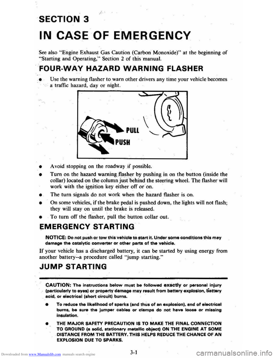
• Turn on the hazard waming"nas~,er by pushing in on the button (inside the collar) located on the column just 'behind the steering wheel. The flasher will work with the ig1J.ition key either ofT or -on.
• The turn signals do not work when the hazard flasher is on.
• On some vehicles. if the brake pedal is pushed down, the light s will not flash ;
they will stay on until the brake is released .
• To turn ofT the flasher, pull the button collar out ..
EMERGENCY STARTING
NOTICE: Do not push or tow this vehiele to start it. Under some eonditions this may damage the catalytic converter or other parts of the vehicl ••
If your vehicle has a discharged battery. it can be started by using energy from
another bauery .. a procedure called "jump starting."
JUMP STARTING
CAUTION: The instructions below mllst be followed ..,x8ctly or personal Injury (particularly to eyas) or property damege may result from banery explosion, ';-attery acid. or "ectrical 'short Circuit, burns.
• To reduce the likelihood of sparks 'and thus of an exp&oslon) , and of electrical
burns. be sure the jumper cab," or ciampa do not hev. 100 .. Of m;uing insulation.
•
THE MAJOR SAFETY PRECAUTlON IS TO MAKE THE FINAL CONNECTION
TO GROUND (a solid, stationary metallic object) ON THE ENGINE AT SOME DISTANCE FROI'II THE BATTERY .. THIS HELPS REDUCE THE CHANCE OF AN EXPLOSION DUE TO SPARKS.
3-1
Page 49 of 95
Downloaded from www.Manualslib.com manuals search engine • To lessen the chance of an explosion, never expose a battery to open flames
or electric sparks. Also do not smoke near a ,battery. Batteries give off a gas which is flammable and explosive.
• To lessen the risk of injury incase an explosion does occur, wear eye protection or shield your eyes when working near any battery. Do not lean over a battery.
• Do not allow battery fluid to contact eyes, skin, fabrics, or painted surfaces
because battery fluid is a corrOsiVe acid. Flush any contacted area with water immediately a,nd thoroughly. Also get medical help if eyes are affected.
• To lessen the riskofa short circuit. remove rings, metal watch bands and otl:ler metal jewelry. Also do not allow metal tools to contact at the same time the positive battery terminal (or any metal connected to this terminal) and any other metal em either "ehicle. Make certain when attaching the jumper cable clamps rothe positive terminals of the batteries that neither clamp contacts any other metal.
• This
vehicle has a 12 volt battery and a negative ground electrical system. Make sure that the other vehicle als~ has a 12 volt battery and that the negative terminal, is .'grounc::ted(attached to a metal, part of the vehicle). Its owner's manual may give you that information, If unsure of the other vehicle's voltage (or if the voltage and/or ground on the other vehicle are different from your vehicle). do not try to jump startas personal injury or severe damage to electrical and electronic parts may result.
• If the discharged battery has filler caps. check the fluid level. ( 00 not check with an Op~tn flame and db not smoke .) Add clear drinking water to the proper level if low, and replace the caps before jump starting.
I. Position, the vehicle with'the good (charged)ba,.ttery so that the jump starting
cables will reach.
Do not let the vehicles t"ouch.
2. Turn off all electric motors and accessories in both vehicles. Turn off all lights
except those needed to protect the vehicles or light up the work area. Turn
off the ignition, apply the parking brake firmly, and shift the automatic transaxleto "p"o.?ark) (manual transaxle to "N"(Neutral) in both vE-hicles.
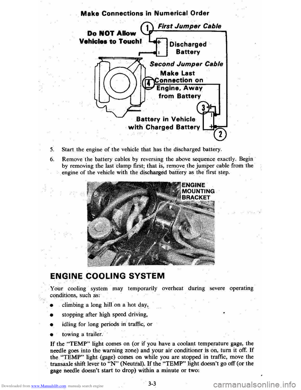
3. Jumper Cable Connection Instructions (See illustration) .
• Connect the first jumper cable from the positive" +" (red) terininal on
one battery to the positive "+" (red) terminal on the other battery.
Never, connect "+" (red) to "~" (black), or '\" to "+".
• Next, connect one end of the second cable to the grounded negative "."
(black) tenninal of the good (charged) battery.
• Lastly, connect the othetend of the second jumper cable to a solid,
stationary, metallic point on the engine of the vehicle with the discharged
battery but at a
point away from the battery --450 millimeters (18 '1
inches) or more from the battery if possible. Do not connect it to or attach it near pulleys, fans, or other parts that will move wHen the engine
is started. Don't touctt hot manifolds as they _can cause severe burns. If hot or moving parts can be avoided, the MOUNTING BRACKETS for
the Delcotron generator,
or the air conditioner compressor, ,generally
make a good point for-this final ground attachment. Take care that the
jtimper cable does
hot contact moving parts on or near the generator
or compressor.)
4. Start the engine of the vehicle with the good (charged) battery and run the
engine at a moderate speed.
3-2
Page 50 of 95
Downloaded from www.Manualslib.com manuals search engine Make Connections In Numerical Order
First Jumper Cable
Discharged
Battery
Make Last
onnectlon on
Engine. Away
from Battery
Battery in Vehicle
with Charged Battery LC"""=-
5. Start the engine of the vehicle that has the discharged battery.
6. Remove the battery cables by reversing the above sequence exactly. Begin
by removing the last clamp first; that is, remove the jumper cable· from the engine of the vehicle with the' discha:r,g:edbatTery as the' first step.
ENGINE COOLING SYSTEM
Your cooling system may temporarily overheat during severe operating
conditions, such as:
• climbing a long hilLon a hot qay,
•
stopping after high speed driving,
• idling for long periods' in' traffic, or
• towing a trailer.
If theUTEMP" light comes on (or if you have a coolant temperature gage, the
needle goes
into the warning zone) and your air conditioner is on, tum it off. If
the. 'ITEMP" light (gage) comes on while you are stopped in traffic, move the
transaxle shift lever to UN" (Neutral). If the "TBMP" light doesn't go off (or the
gage
needle doesn't start to drop) within a minute or two:
3-3
Page 70 of 95
Downloaded from www.Manualslib.com manuals search engine CAUTION: If the air cleaner is removed during repair or maintenance, be sure to . put It back on correctly. If the air cleaner is not correctly installed, there could be II fire In the engine compartment (if there should happen to be a backfire), or other engine malfunction.
Power Steering System
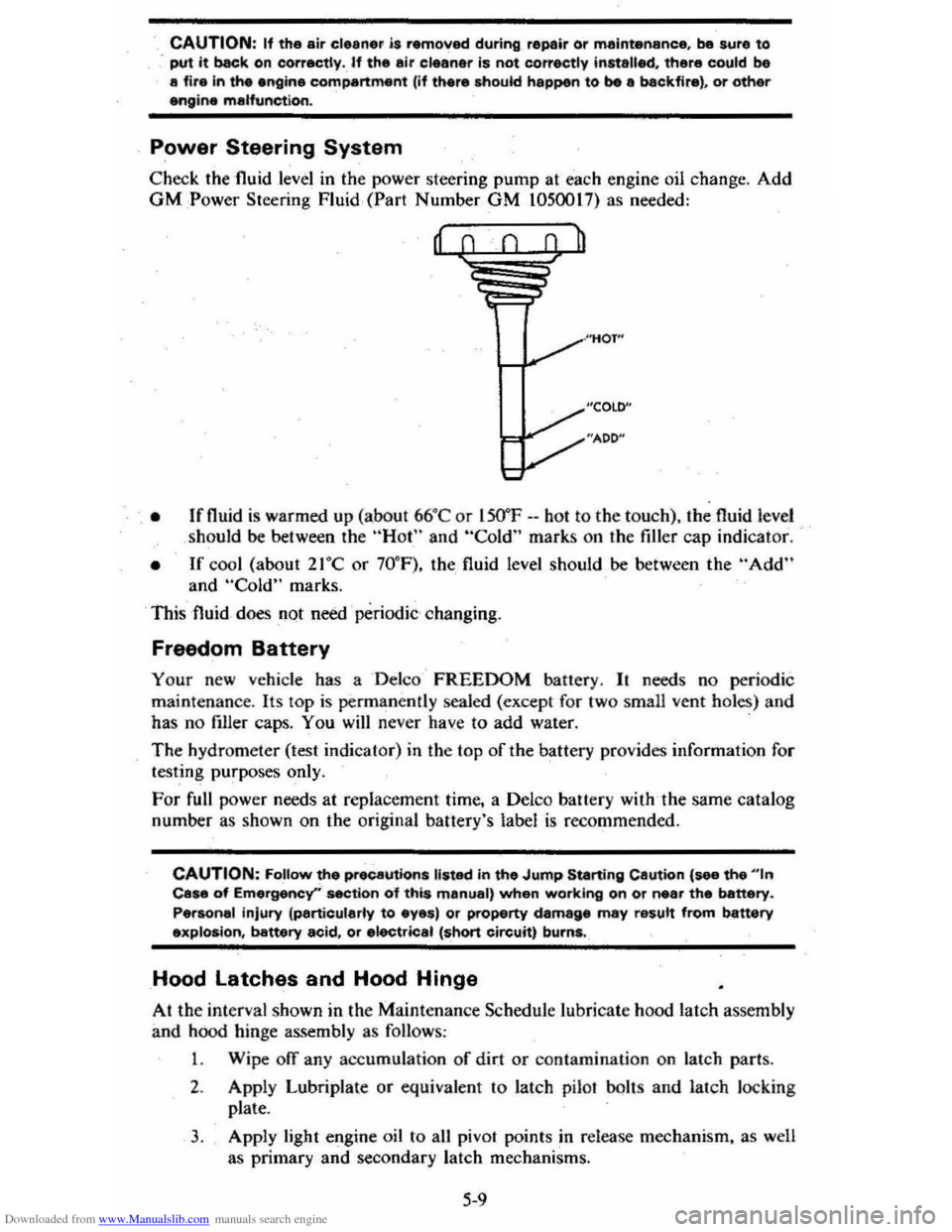
Check the 'fluid level in the power steering pump at each engine oil change. Add GM :Power Steering Fluid, (Part Number GM 1050017) as needed:
, • Ifnuid is warmed up (abo ut 66°C or lSO"F --hot to the to uch), the fluid level
should be between the "Hot" and "Cold" marks on the filler cap indicat or.
• If cool (about 21°C or 70° F), the fluid level should be between the "Add" and "Cold" marks.
This fluid
does not need ' periodic changing.
Freedom Battery
Your new vehicle has a Delco FREEDOM battery. It needs no periodic
maint enance . Its
lOp is permanently sealed (except for two small vent holes) and
has no filler caps. You will never have to add water. .
The hydrometer (test indicat or) in the top of the battery provides information for
testing purposes only.
For full power needs at repla cement time, a Delco battery with ,the same catalog
number as shown on the original banery's label
is recommended.
CAUTION: FoUow the precautions listed in the Jump Starting Cautton {see the "'n Case of Emergency''' section o"f this manual, when working on or near the battery.
Personal injury (particularly to eyes) or property damage may result from battery explosion, battery acid, or electric.1 (short circuit) burns.
Hood latches and Hood Hinge
At the interval shown in the Maintenance Schedule lubricate hood latch assembly
and hood hinge assembly as follows :
1 . Wipe off any accumulation
of dir.t or contamination on latch parts.
2. Apply Lubriplate or equivalent to latch pilaf bolts and latch loc king
plate .
3. Apply light engine oil to all pivot points in release mechanism, as well
as primary
and secondary latch mechanisms.
5-9
Page 83 of 95
Downloaded from www.Manualslib.com manuals search engine . SECTION 7
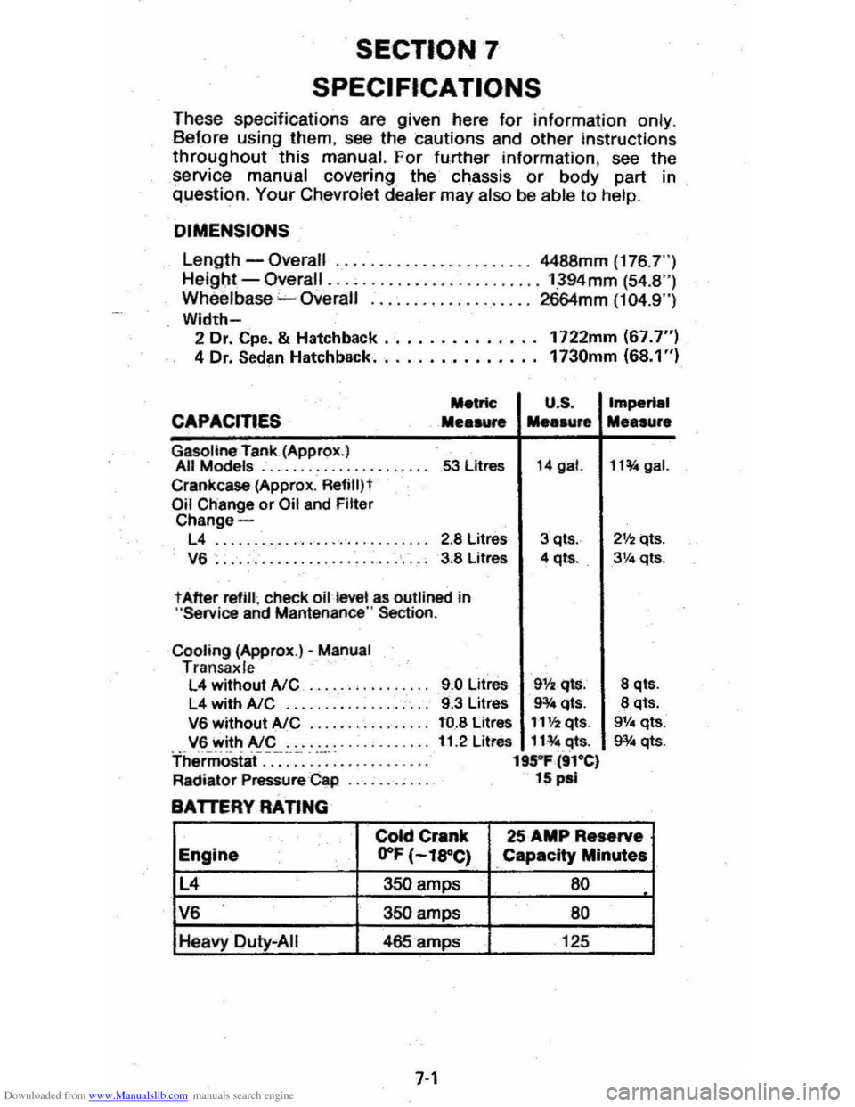
SPECIFICATIONS
T hese specifications are given here for information on ly . B efore using them, see the cautions and other instructions
throughout this manual. For fu.rther information , see the
service manual covering the chassis or body part in question. Your Chevrol et dealer may also be abl e to help.
DIMENSIONS
Length -Overall ......... , •.... , •...... 4488mm (176 .7")
He igl;lt -Overall ......................... ':394mm (54.8 ") Wh eelbase "-Overall ................... 2664mm (104.9")
Width-2 Dr. Cpe. & Hatchback .· ............. 1722mm (67.7") 4 Dr. Sedan Hatchback.. . . . . . . . . . . . .. 1730mm (68.1 ")
Metric U .S .
CAPACITIES Mea .... .... .ur.
Gasoline rank (Approx.) All Models .................... 53 litres 14 gal.
Crankcase (Approx . Refililt Oil Change or Oil and Filter Change-
L4 ........ ........... '. ' .. ... 2.8 Litres 3 qts .
V6 . . . . . , . . . . . . . . . . . . . . . . . . . . . . 3 :8 Litres 4 qt • . .
t After refill ; check oil kwel as outlined in "Service and Mantenance " Section .
Cooling (Approx.)· Manual Tran sa x le L4 without AlC ..... . , .. .
L4 withA/C .... ... ........... .
V6 without AlC ...... ...•...... V6 with AlC ....... . Thermostaf.-.-:~-~-. -....... : ....... .
Radiator Pressure Cap
BATTERY RATING
9.0 Litre. 911 •. qls. 9.3 Litres 9¥4 qts.
to.8 Litres 1'1'12 qts.
11.2 Litres 11¥ " .c:Jts. 195"1' (91·e) 15 pal
Imperial
Me.sure
11~gal.
21f2qts .
3Ve qts.
8 qt •.
8 qts. 9V .. qts.
g¥ .. qts.
colci Crank 25 AMP Reserve
Engine .. O"F (-l8"C) Capacity Minutes
L4 350 amps 60
V6 350 amps 80
Heavy Duty "AIi 465 amps 125
7-1
Page 95 of 95
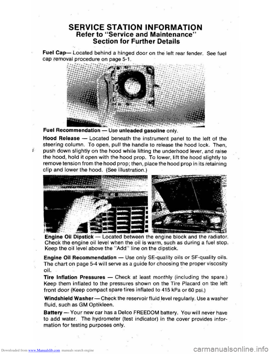
Downloaded from www.Manualslib.com manuals search engine SERVICE STATION INFORMATION
Refer to "Service and Maintenance"
Section for Further Details
Fuel Cap-Located behind a hinged door on the lett rear fender. See fuel cap removal procedure on page 5-1.
Fuel Recommendation -Use unle~ded gasoline only .
Hood Release -Located beneath the instrument panel to the left of the
steering column. To open, pull the handle to re lease the hood lock . Then ,
j" push down slightly o "n the hood whil e lifting the underhood lever, and raise
the hood, hold it open with the hood prop. To lower, lift the hood slightly to
remove tension from the hood
prop; then , place the hood prop in its retainin g
clip and lower the hood. (See illustration.)
Engine Oil -located between the engine block and the radiator. Check the engine oil level when the oil is warm, such as during a fuel stop. Keep the oil level above the "Add" line on the .dipstick.
Engine Oil Re "commendatlon -Use only SE-q ualit y oils or SF-quality oils .
The chart o n page 5-4 will serve as a gu ide tor choosing the proper viscosity oil. .
Tire Inflation Pressures -Check at least monthly (including the spare .)
Keep them
inflated to the pressures shown on the Tire Placard on the left
front door (Keep compact spare tires inflated to 4t5 kPa or 60 psi.)
Windshield Washer-Check the reservoir fluid level regularly . Use a wa sher
fluid, such as GM Optikleen.
Battery -Your new car has a Delco FREEDOM battery. You will never have
to add water. The hydrometer (test indicator) in the cover provides infor
mation for testing purposes only.