1980 CHEVROLET CITATION air condition
[x] Cancel search: air conditionPage 15 of 95
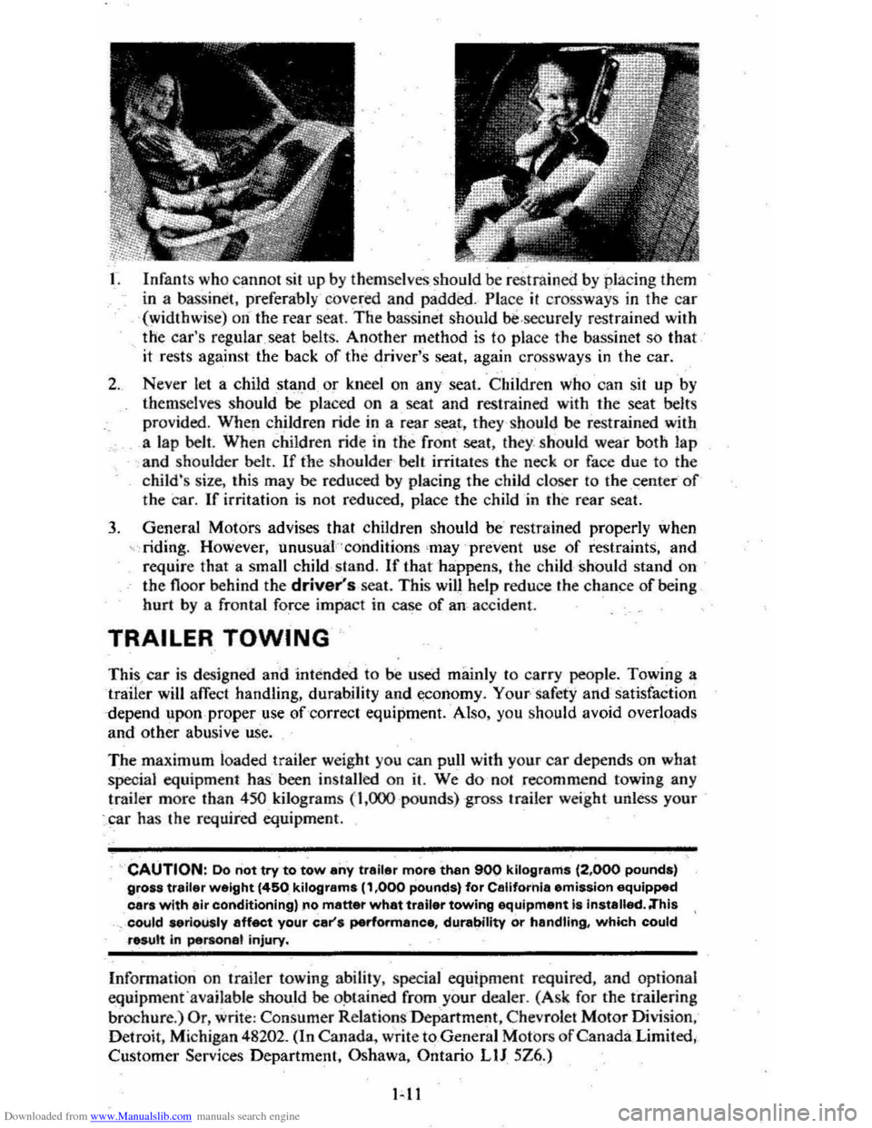
Downloaded from www.Manualslib.com manuals search engine L Infants who cannot sit up by themselves should be restr~ined b y placing them
in a bassinet, preferably cove~ed and padded .- Pl ace il crossways in the car
(widthwise) on-the rear seat.
The bassi net should bi!.secure ly restrained with
the car's reg ular seat belt
s. Another method is to pla ce the bassinet so that
it rests aga,inst the back of the driver's seat, again crossways in the car.
2. Never let a child sta~d or kneel on any seat. Children who can sit up by
them selves should be placed on a seat and restrained with the seat belts
provided. When children ride in a rear se:at, they should be restrained with
a lap
belt. When children ride in the fronf seat, they . ,should wear both lap
and
shou'lder belt. If the shoulder bell irritates the neck or face due to th e
child's size, this may be reduced by placing the child closer to the center of the car. If irritation is not red uced, place the child in the rear seat.
3. General Motors advises that children should be restr ained properly when
riding . However, unusual'~conditions 'may prevent use of restraints, and
requir e that a small child,
sland. If that happens, the c hild should stand on
the floo r behind the driver's seat. This will help reduce the chance of being
hurt
by a frontal force impact in case of an accident.
TRAILER TOWING
This car is designed and intended to be used mainly to car ry people. Towing a
trailer will affect handling, durability and economy_ Your'"safcty and satisfaction
depend upon,proper use
of correct equipment. Also. you should avoid overloads
and other abusive use.
The maximum loaded trailer weight you can pull with your car depends
on what special equipment has-been inst alled o n it. We do-n o t recommend towing any
trailer more than 450
kilograms (1,000 pounds) -gross trailer weight unless your
'car ha s .he required equipment.
CAUTION: Do not try to tow any trailer more than 900 kilograms (2.000 pounds)
gross trailer weight (450 kilograms (' .000 pounds) for California emission equipped
cars with air conditioning) no matter what trailer towing equipment is installed. ;This ,could .eriously affect your car'S performance. durability or handling. which could
result in personel injury.
Infonnati on on trailer towing ability, special equipment requir ed, and optional
equipm e
nfavailable should be o~lained from your dea ler . (Ask for the trailering
brochur e.)
Or, write: Consumer Relat ions Department , Chevrolet Motor Division ,
Detroit , Mi chigan
48202. (In Canada, write to General Motors of Canada Limited .
Custom
er Services Department, Oshawa. Ontario LlJ 5Z6.)
Page 17 of 95
Downloaded from www.Manualslib.com manuals search engine NOTICE: Use only trailer hitches which permit normal operation of the Energy Absorbing Bumper System. if so equipped. For example. a rigid fore and .iUt connection between the bumper and any other part.of. the car may increase .damage in the event of II collision.
TRAILER TOWING TIPS
Getting Started
Before entering traffic with a frailer that has electric brakes, start the car and
trailer moving and apply the trailer brakes
by hand to be sure the trailer brakes
are working and the trailer electrical system
is connected .
. Engine Cooling
:
When going up long grades, you, can reduce the chance 'of engine overheating by
turning
off the air conditioner, if so equipped.
Transaxle
,See the method for checking the transaxle fluid le ve l. in "Service and
,.;.Maintenance," Section 5 of this manual .
Parking
You should not park cars with trailers on a grade (hill). However, if you must
park on a grade, these steps must be followed:
1. Apply the regular brakes.
2. Have someone place wheel' chocks under the trailer wheels.
3. When the wheel chocks are in place, release the regular brakes until the
chocks absorb the load .
4; Apply Ihe parking brake.
S. Shift Ihe transaxle 10 ··P"(Park).
If the car is parked on a grade. don't shift the transaxle 10 "P"(Park) until the
trailer wheels
are chocked and the parkinghrake, is set~ If you do, the weight of . the car and trailer may put so much force on the parking pawl in the transaxle
.
that it may be hard to shift oul of "P"(Park).
When starting , after being parked ' on a grade:
(; Apply the regular brakes and hold.
2 .
Stan th e engine in ··P"(Park) .
-3. Shift into gear and release the parking brake.
4. Release the regular brakes and drive until the chock s are free.
5. Apply the regular brakes and have your helper remove the chocks.
J.]3
Page 18 of 95
Downloaded from www.Manualslib.com manuals search engine SECTION 2
STARTING AND OPERATING
ENGINE EXHAUST GAS CAUTION
(CARBON MONOXIDE)
Do not breathe exhaust gas becau~ it contains carbon monoxide, which by itself
- has no color or odor. Carbon monoxide is a dangerous gas . .It can cause
un consc iousness and can
be lethal.
If at any time you think that exhaust fumes are entering the vehicle. have the cause determined and corrected as soon· as possible. If you must drive under these
conditi<:ms, drive only with ALL windows fully OPEN.
Prptect
against carbon monoxide entry ihtp the vehicle body. The best way is to
keep the engine -exhaust system, vehicle
body. and body ventilation system
properly maintained. We recommend that the exhau st system and body be "inspected by a competent mechanic: '
• each time the vehicle is raised for an oil change;
• whenever a change is noticed in the',sound ofthe~exhaust system;
• wh enever the exhaust sys.tem. underbody . or rear of the vehicle is damaged.
See your Maintenan ce Schedule fo.~4er for parts requiring inspection .
To allow proper operation of the vehicle's ventilation system, keep the air inlet
grill e
in front of the win(fshield clear of snow, leaves or other obstru ctions at all
times.
SITTING IN A PARKED VEI:iICLE WITH THE ENGINE RUNNING FOR A LONG TIME IS NOT RECOMMENDED.
Do n ot fun , the engine in co nfined areas (such as garages or next to a building)
any more than needed to move the vehicle. When the, vehicle is stopped in an
UNCONFINED area with the engine running for any, more than a sho rt time, tak e the following steps:
A. Adju st the heating or cooling system to force outside air into the vehicle as
follows:
1. On cars not equipped with air co nditioning . se t the fan to medium or
high speed.
2. On cars equipped with air conditioning, serthe fan to medium or high
spe ed
a!1;d right hand control lever' to any position except "orr' or ·'Max."
-B. Keep the exhau st tailpipe -area clear of snow and other material to help"reduce
the buildup of exhaust gases' under the vehicle .
The ,trunk lid or hatchba ck should be closed while driving to help prevent drawing
exhaust gas into
the car. If the trunk lid or hatchback mu st' remain open for some
rea son while moving , or
if electrical wiring or other cable conn_ection s to a trai ler
_mu st pass through the sea l between the trunk lid or hatchba ck and -the body . follow
thes e precautions:
• Close all wind ows.
2-1
Page 22 of 95
Downloaded from www.Manualslib.com manuals search engine Air Conditioner
If your vehicle has an optional air cOnditioner , use the "Economy;' (" Vent" or
"Heater") position s whenever possible, The air conditioner compr essor is not on in these positions and the reduced engine load can improve fuel eco nomy.
Engine Maintenance
An engine that is properly maintained wjJl provide better fuel economy than .one
thai is not . One misfirin g spa rk plu g will cut fuel economy quite a bit , and will
make a difference in the amount of pollution _emitted fro m your vehicle .
Excess Weight
Fuel economy is related to the work the engine must do. The heavier the load,
the more fuel
it takes to run your vehicle. Keep weight to a minimum by taking o~t any luggage or cargo when it is not needed. .
Tire Inflation
Underinflation not only causes needLess wear of the tires, but can also waste fuel. It's a good idea to check tire pressures often and, for the best fuel econ omy, keep
your tires inflated to the highest
pr~suresshown on the Tire Placard on'the left
front doo r of your car.
Wheel Alignment
Improper toe alignment will cause the tires to roll at an angle, which will result
in faster tire wear.
It takes power to ove rcome this improper alignment which,
in tum, wastes fuel.
STEERING COLUMN CONTROLS
ANTI-THEFT STEERING COLUMN LOCK
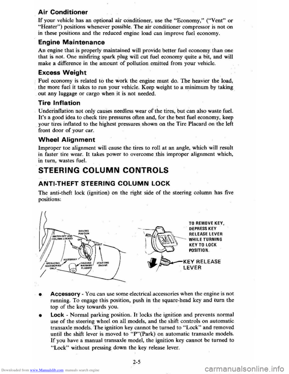
The anti-theft lock (ignition) on the right side of the steering column has five
positi on
s:
TO REMOVE KEY, DEPRESS KEY \&!;;>. RELEASE LEVER
-~ I
~~~ --WHILE TURNING KEY TO LOCK POSITION
.. ~'-KEY RELEASE "..~ LEVER
• Accessory -You ca n use some elec trical a ccessories when the e ngin e is not
running.
To engage this position, push in the square-head key and tum the
top of the key towards you.
• Lock -Norm al parking position. It 'locks the ignition and prev en ts normal
use
of the steering wheel on all models, and the shift controls on automatic
transaxl e model
s. The ignition key canno t be turned to "Lock" and removed
until the shift lever is mo ved to "P "( Park) on automatic transaxle mode1s .
If you have a manual transaxle model, the ignition key cannot be turned to
"Lock" without pressing down the key release leve r.
2-5
Page 34 of 95
Downloaded from www.Manualslib.com manuals search engine Oil/Choke Indicator Light
This light will c0!TIe on to provide a "bulb check", w hen the igni tion is turned on, but sh Qu19 go out after the _ engine is started. If tight fails to
come on wit h ignitio~ turned on, it could indicate a burned out bulb , a
defective electric choke hea ter circuit (on L4 and V6 engines), or a blown
instrument lamp fuse. Have system repaired if light does not come on d min g ch eck .
Occa sionally. this light may flicker momentarily while the engine is running. Should this occur, CHECK EN GINE OIL LEVEL as outlined in Section 5,
"Checking Oil Level." If the light comes on continuously, pull over toa safe place and STOP THE ENGINE until the source of trouble can be loca ted and corrected.
The source of tro uble could be any of the following:
• Loss of engine oil press ure (cbec k eng ine oil level).
• Blown choke heater fuse.
• Loss. of electric choke heate r voltage.
Continuing to run the engine with an illuminated oil pressure light can cause
serious engine damage or unusu ally high exhaust system temperature which can
r esult in serio us damage to the
vehicle. Pull over to a safe place and STOP THE
VEHICLE IMMEDIATELY AND SHUT OFF ENGINE. If the light flashe s
momentarily , ch
eck engine oil leve l as outlined in Sectio n 5 of thi s manu al
Choke Warning Indicator Light
On some vehicles equipped with the optiona l oil pressure gage, an amber choke
warning indicator light replaces the red oil pressure indicator light in the
instrument cluste
r. If this light comes on, indicating loss of electric choke heater
volta
ge, have your authoriz ed Dea ler .locate and correct th e tro uble as soon as
p ossib l
e.
Generator Indicator Light The red ligh t GEN will go on when the ignition key is in the "run" _posit ion, but
before the engi ne
is started. After the engine s tarts, the light should 'go out and
r e m ain out .
If th e light remains on when en gine is running , have your Authorized
D eale r loca te and correct the troubl e as soo n as possibl
e.
Engine Temperature .Indicator Light This indicator light is provided in th e instrument cluster to quickly warn of an
overh eated en gi ne. With the igniti on switch in the START position, the red
TEMP indicator (hot light) will light to let you know that it is operati ng prope rly.
When the engi ne is started ;-th e re d light will go out imm ediate ly. It wilUight up
a t n o other time unleSS for some reason the engine reaches a dangerously high ope ra tin g temperature . 1f the light comes on during extreme driving condition s,
such as an exte nded idle, see "E ngine Cooling
System" on page 3-3. Glance at
th e instrument cluster frequently as you drive to see if this
ligh t is on.
Brake System Warning Light
The regular braking system is a dual system designed so that one part will provide
some braking action if there is a loss of hydraulic pressure in the other part of
the system. The system has a "Brake" warning light loca ted in the instrum ent
pane\.
• To serve as a reminder , the "Bra ke" lig ht is designed to come on while the
park ing brake is se t and the ignition key
is on.
• The light is also designed to come on briefly during engine starting so you
can chec k that the bulb is okay.
• Have the system repaired if the light does not come on during engine starting
o r when the parking brake
is set. 2-17
Page 36 of 95
Downloaded from www.Manualslib.com manuals search engine Engine Temperature Gage
This gage indicat~cCX?lant temperature which will vary with air temperature and
operating condition~, The ignition must be on for accurate readings. Hard driving
or prolonged idling In very hot weather will cause the pointer to move beyond the center of the band; Should pointer move to the Red Zone, see "Engine Cooling
System" on page 3-3.
Oil Pressure Gage
The oil pressure gage indicates the pn;ssure at which oil is being delivered 10 the various parts of the engine requiring lubrication. Pressures registered by the gage
I11.!lY vary according to outside air temperatures or weight of oil being used. Oil
pressure of a cold engine ~ing operated at a given speed will be somewhat higher
than when the engine is at normal operating temperature at the same speed .
. Prolonged high speed operation on a hot day at the given speed will result in somewhat lower oil pressure readings. Readings of 30 to 40 psi (205 to 275 kPa)
mny
be considered normal during moderate road speeds of 35 to 40 mph (55 to
60 km/h) \\lith the engine at proper operating temperature. Gage readings which
are
consistently high or Im\l under these conditions may indicate lubrication system
When the engine is operating, the voltmeter indicates the electrical system voltage.
During minimum electrical load, the pointer will read to the right of the center.
As the electrical load is increased,
or in stop-and-go driving, the pointer will rotate
to the left. A meter reading continuously in
the left or right red zone indicates
an electrical system
failure .. Cause of the failure should be determined and corrected~
Light Switch
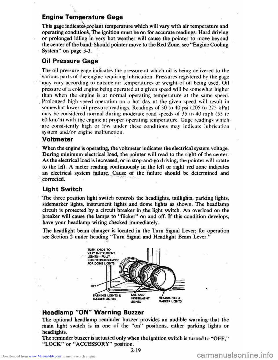
The three position light switch controls the headlights, taillights, parking lights,
sidemarker lights, instrument lights and dome lights as shown. The headlamp
circuit is protected by a circuit breaker in
the light switch. An overload on the
breaker will cause the lamps to "flicker" on and off. If this condition develops,
have your headlamp wiring checked immediately.
The headlight beam changer is located. in the
Turn Signal Lever; for operation
see Section 2 under heading "Tum Signal and Headlight Beam Lever."
TUIN KNOt TO VAr:t'INSTRUMENT lIGHTS_'UtLy COUNTERClOCKWISE RlR DOME
0"
MAltlCfIt LIGHTS , INSTRUMENT LIGHTS
Headlamp "ON" Warning Buzzer
The optional headlamp reminder buzzer provides an audible warning that the
main light switch is in one
of the "on" positions, either parking lights or
headlights.
The reminder buzzer
is actuated only when the ignition switch is turned to "OFF," "LOCK" or "ACCESSORY" position.
2-19
Page 37 of 95
Downloaded from www.Manualslib.com manuals search engine When the parking lamps or headlamps are to be operated with the key in the OFF position. the reminder buzzer can be shut off by turning the light switch knob
until the instrument cluster lights are not on.
Electric Clock
Reset the clock, . if your vehicle is so equipjled. by pulling out the knob and turning the hands clockwise if slow, counterclockwise if fast. This win, if the clock error
is five minutes or more, automatically compensate for time' gain or lag. Several
reseuings, several days apart. may be needed to properly adjust the c10ck
mechanism.
Cigarette Lighter
The optional cigarette lighter is located "in-the ash tray. To operate,- -push it in.
When it becomes heated, it automatically pops out ready for use. ,
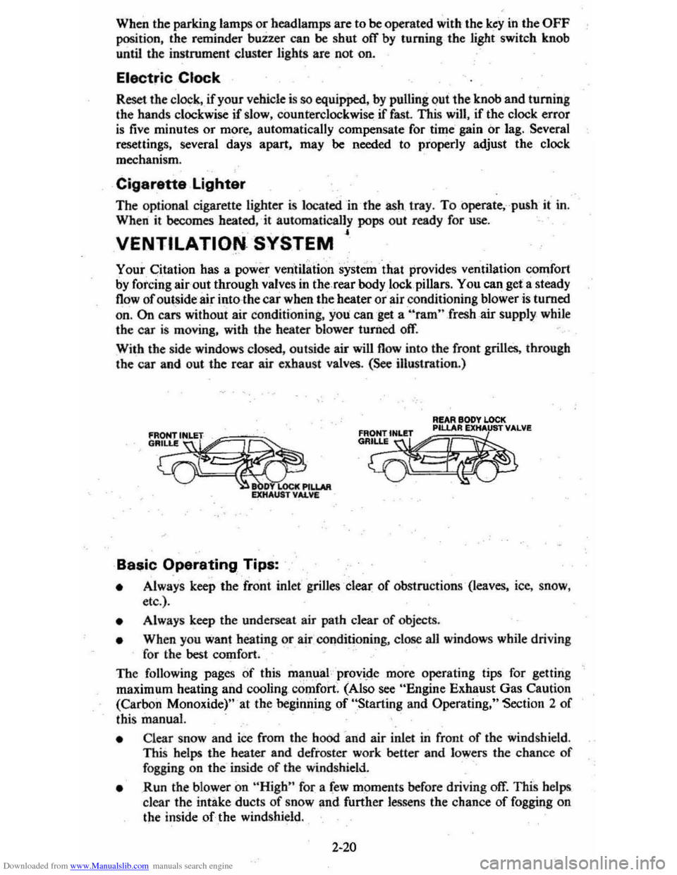
VENTILATION. SYSTEM
Your Citation has a power verttiI3:tion system' that provides ventilation comfort by forcing air out through valves in the rear body lock. pillars. You can get a steady
flow of outside air into the car when the heater ot air conditioning blower is turned
on, On cars without air conditioning, you can get a "'ram" fresh .air supply while
the car is moving, with the heater blower· turiled off.
With the side windows closed, outside air will flow into the front grilles. through the car and out the rear air exhaust valves. (See illustration.)
fRONrlNLET
G~.
LOCt
R!AR BODY LOCK
~~~m
• Always keep the fro'nt inlet' grilles clear of obstructions ' (leaves, ice, snow,
etc .).
• Alw.ays keep the underseat ai r path clear of objects.
• When you want heating or air COllditioning, close aU windows while driving
for
the best comfort.
The following pages of this mlin,ual provi.de more operating tips for gettina
maximum heating and cooling , comfort. (Also see "Engine Exhaust Gas Caution
(Carbon Monoxide)" 'at the begiiuling of "Starting and Operating," Section 2 of
this manual.
• Clear snow and ice from the hood 'and air inlet in front of the windshield . This helps the heater and defroster work better and lowers the chance of fogging on the' inside of the windshield.
• Run the blower on "High" for a few moments before driving off. This helps
clear the intake ducts of snow and further lessen s the chance of fogging on
the inside of the windshield.
2-20
Page 38 of 95
Downloaded from www.Manualslib.com manuals search engine lower Air Vents
Two control handles lOCated beneath the steering column open and close the tower
air vents. To compliment this system there is a power upper vent in the instrument
panel which is operated from the heater
control. The amount of air coming from the lower cutlets ~epends -on vehicle speed and the upper outJet~ depend on fan
'poed.
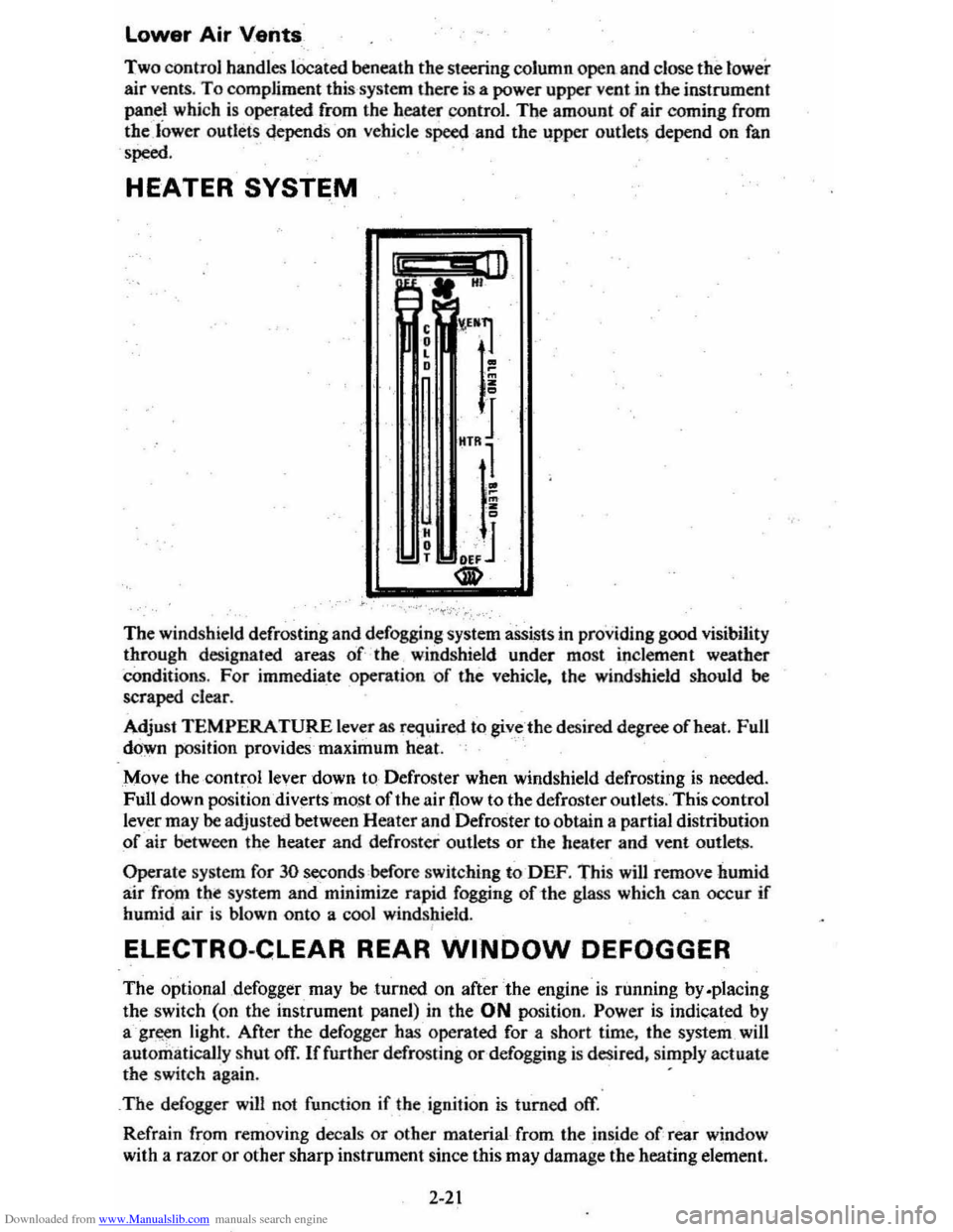
HEATER SYSTEM
I" .. ill A. HI
The windshield defrosting and defogging system assists in providing good visibility through designated areas of the windshield under most inclement weather
Conditions. For immedia_te operation of the vehicle. the windshield should be scraped clear.
Adjust
TEMPERATURE lever as required to giv_c -the desired degree afheat. Full
down position provides'maximum heat.
Move the ·
controllever down to-Defroster when windshield defrosting is needed.
Full down position diverts most of the air (low to the defroster outlets. This control
lever may
be adjusted between Heater and Defroster to obtain a partial distribution
of air between the heater and defroster outlets or the heater and vent outlets.
Operate system for 30 seconds before switching to-DEF. This will remove humid
air from tht system and minimize rapid fogging of-the glass which can occur if humid air is blown onto a cool windshield.
ELECTRO-CLEAR REAR WINDOW DEFOGGER
The optional ,defogger may be turned on after the engine is running by.placing
the switch (on the instrument panel) in the ON position. Power is indicated by
agr~n light. After the defogger has operated for a short time. the system _will
automatically
shut ofT. If further defrosting or defogging is desired. simply actuate the switch again. .
_
The defogger will not function if the ignition is turned off.
Refrain from removing decals
or other material from the inside of rear window
with a
razor or other sharp instrument since this may damage the heating element.
2-21