1980 CHEVROLET CITATION air condition
[x] Cancel search: air conditionPage 39 of 95
Downloaded from www.Manualslib.com manuals search engine Clear snow and ice from the rear window to improve the efficiency of the reaT
window defogger.
Air Outlets
The twin barrel vertical type center outlets maybe rotated or vanes turned to direct
air flow in direction desired. The outlets at each end of the instrument panel-may
be rotated or vanes adjusted as desired.
AIR CONDITIONING SYSTEM
This system combines heating and cooling capabilities for comfort in all weather
conditions.
During some air conditioning operation conditions, slight increases and decreases
of engine speed/power may be noticed. This should be considered normal, as the
system
is designed to cycle the compressor -ON and OFF to maintain desired
cooling. The reduced compressor operation should benefit fuel economy.
III
~" HI
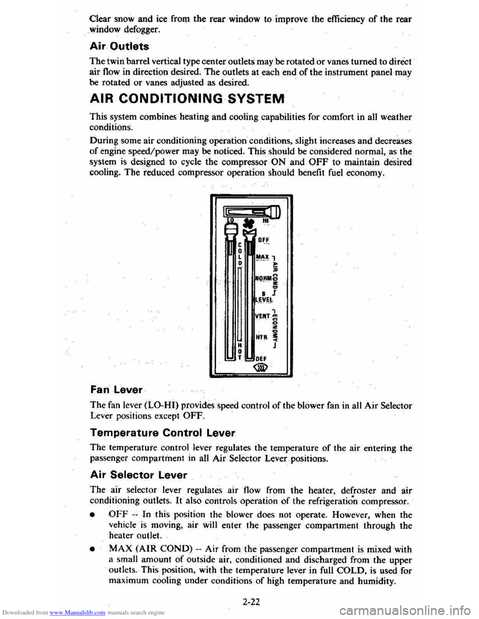
Fan Lever
,
• L •
H • T
O,!
!1~)t 1 ~ ~ ORMS . 2
• I _~v~
VEN.T_~ o ;; HTR ! J
." ®
The fan lever (LO-HI) provides speed control of the blower fan in all Air Selector Lever positions except OFF.
Temperature Control Lever
The temperature control lever regulates the temperature of the air entering the
passenger compartment in an Air Selector Lever _ positions.
Air Selector Lever
The air selector lever regulates air flow from the heater, defroster and air
conditioning outlets.
It also controls operation of the refrigeration compressor.
• OFF --In this position the blower does not operate. However, when the
vehicle is moving, air will enter the passenger compartment through the
heater outlet.
• MAX (AIR COND) --Air from the passenger compartment is mixed with
a small amount
of outside air, conditioned and discharged from the upper
outlets. This position, with the temperature lever in full
COLD, is used for
maximum cooling under conditions
of high temperature and humidity.
2-22
Page 40 of 95
Downloaded from www.Manualslib.com manuals search engine • NORM (AIR COND) --Outside aids conditioned as it passes through the
system and is discharged from the upper outlets. This position is used for most
air conditioning situations.
• BI-LEVEL (AIR COND) --Outside air is conditioned and directed out the
upper outlets PLUS the heater outlet. A small amount of air also flows from
the defroster outlets. This position provides comfort
and keeps the windshield
clear under low fogging conditions.
• VENT (ECONOMY)-- Outside air is discharged from the upper outlets. This
position is used in cool to moderate weather when refrigeration is not
required. The refrigeration compressor
is turned off.
• HEATER (ECONOMY) --Outside air is delivered from the heater outlet
with a small amount from the defroster outlets. This position is used for most
winter driving. The compressor
is turned off.
• DEF --Outside air is conditioned and delivered from the defroster outlets
with a small amount from the heater outlet. This position is recommended
for conditions of severe fogging and icing only.
Operating Tip
For satisfactory operation of the air conditioning system, windows should always
be closed, except for the
first few minutes to remove hot air if the car has been
sitting.
Air Outlets
Thetwin barrel vertical type center outlets may be rotated or vanes turned to direct
airflow in direction desired. The outlets at each end of the instrument panel may
be rotated or vanes adjusted as desired.
RADIOS
Your vehicle may have one of several optional GM Delco Sound Systems.
GENERAL INFORMATION
Basic Controls-Although a wide variety of features is offered, the following
basic controls are common to all systems.
• Upper Knob -This knob tutns the set on or otT, and controls the volume.
(To use the radio; the ignition mustbe in "Run" or "Accessory;" ) Behind
the volume knob-is a tone control. When turned to the right, it increases treble
and voice clarity; when turned to the left, it increases bass.
• Lower Knob -This knob is a manual tuning control for choosing radio
stations. For radios with rear speakers, a fader control is behind it. This
control adjusts the sound between the front and rear speakers.
• Push Buttons -Each radio has five push buttons you can use to select your
favorite stations. After using a push button, you may have to "fine-tune" the
radio by hand for the best reception.
To
"set up" the push buttons:
L Manually tune to the desired station.
2. Choose the button you wish to use. Pull it straight out, then push it back
in firmly until it stops.
3. Do this for each of the buttons.
On Delco AM-FM radios, the "AM" button simultaneously chooses the AM band
and · an
AM station. The FM button simultaneously chooses the FM band and
an FM station. The remaining three buttons may be used to select either an AM
or an FM station.
2-23
Page 41 of 95
Downloaded from www.Manualslib.com manuals search engine Speakers:
NOTICE: All Oelco Sound Systems have ungrounded Sp8li!kers. Installing add-on tape players. CBs or other units that use the vehicle speakers may damage your Delco Sound System and impair operation of the added unit. Please consult your dealer in advance -i f you are conSidering additions.
FM Reception - Although FM is normally static free, reception can be limited by terrain, atmospheric conditions, station strength and distance from the
transmitter. Buildings or other obstructions can cause momentary static, nutter or station swapping. If you cannot keep good reception, tuning to a stronger
station
will bring improvement.
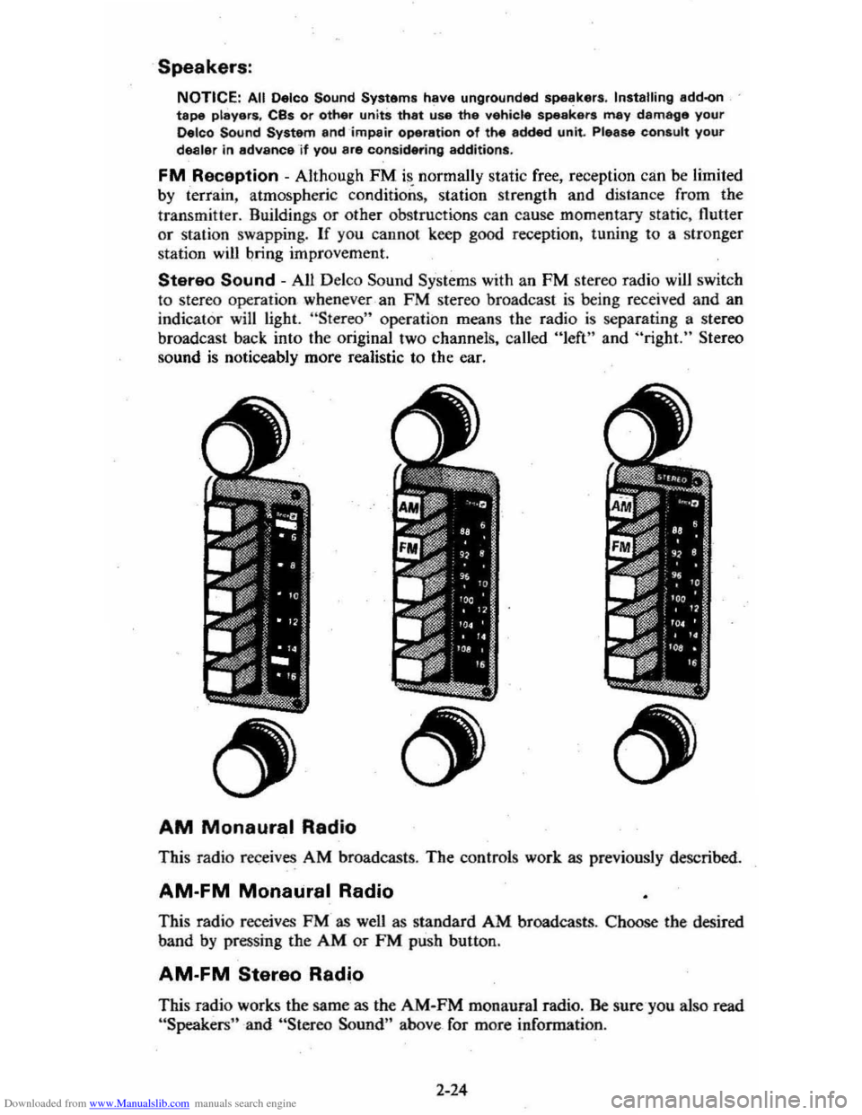
Stereo Sound - All Delco Sound Systems with an FM stereo radio will switch
to stereo operation whenever -an FM stereo broa dcast is being received and an
indicator will light. "Stereo" operation means the radio is separating a stereo
broadcast back into the original two channels, called "left" and "right." Stereo
sound is noticeably more realistic to the ear.
AM Monaural Radio
This radio receives AM broadcasts . The controls work as previously described.
AM-FM Monaural Radio
This radio receives FM as wen as standard AM broadcasts . Choose the desired
band
by pressing the AM or FM push button .
AM-FM Stereo Radio
This radio works the same as the AM-FM monaural radio. Be sure-you also read "Speakers" and "Stereo Sound" above_ for more information .
2-24
Page 49 of 95
Downloaded from www.Manualslib.com manuals search engine • To lessen the chance of an explosion, never expose a battery to open flames
or electric sparks. Also do not smoke near a ,battery. Batteries give off a gas which is flammable and explosive.
• To lessen the risk of injury incase an explosion does occur, wear eye protection or shield your eyes when working near any battery. Do not lean over a battery.
• Do not allow battery fluid to contact eyes, skin, fabrics, or painted surfaces
because battery fluid is a corrOsiVe acid. Flush any contacted area with water immediately a,nd thoroughly. Also get medical help if eyes are affected.
• To lessen the riskofa short circuit. remove rings, metal watch bands and otl:ler metal jewelry. Also do not allow metal tools to contact at the same time the positive battery terminal (or any metal connected to this terminal) and any other metal em either "ehicle. Make certain when attaching the jumper cable clamps rothe positive terminals of the batteries that neither clamp contacts any other metal.
• This
vehicle has a 12 volt battery and a negative ground electrical system. Make sure that the other vehicle als~ has a 12 volt battery and that the negative terminal, is .'grounc::ted(attached to a metal, part of the vehicle). Its owner's manual may give you that information, If unsure of the other vehicle's voltage (or if the voltage and/or ground on the other vehicle are different from your vehicle). do not try to jump startas personal injury or severe damage to electrical and electronic parts may result.
• If the discharged battery has filler caps. check the fluid level. ( 00 not check with an Op~tn flame and db not smoke .) Add clear drinking water to the proper level if low, and replace the caps before jump starting.
I. Position, the vehicle with'the good (charged)ba,.ttery so that the jump starting
cables will reach.
Do not let the vehicles t"ouch.
2. Turn off all electric motors and accessories in both vehicles. Turn off all lights
except those needed to protect the vehicles or light up the work area. Turn
off the ignition, apply the parking brake firmly, and shift the automatic transaxleto "p"o.?ark) (manual transaxle to "N"(Neutral) in both vE-hicles.
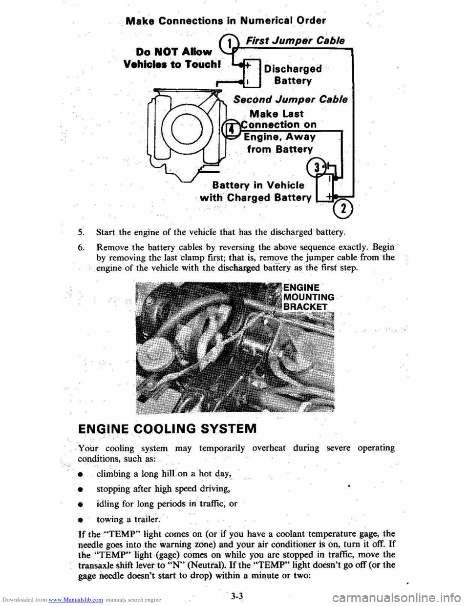
3. Jumper Cable Connection Instructions (See illustration) .
• Connect the first jumper cable from the positive" +" (red) terininal on
one battery to the positive "+" (red) terminal on the other battery.
Never, connect "+" (red) to "~" (black), or '\" to "+".
• Next, connect one end of the second cable to the grounded negative "."
(black) tenninal of the good (charged) battery.
• Lastly, connect the othetend of the second jumper cable to a solid,
stationary, metallic point on the engine of the vehicle with the discharged
battery but at a
point away from the battery --450 millimeters (18 '1
inches) or more from the battery if possible. Do not connect it to or attach it near pulleys, fans, or other parts that will move wHen the engine
is started. Don't touctt hot manifolds as they _can cause severe burns. If hot or moving parts can be avoided, the MOUNTING BRACKETS for
the Delcotron generator,
or the air conditioner compressor, ,generally
make a good point for-this final ground attachment. Take care that the
jtimper cable does
hot contact moving parts on or near the generator
or compressor.)
4. Start the engine of the vehicle with the good (charged) battery and run the
engine at a moderate speed.
3-2
Page 50 of 95
Downloaded from www.Manualslib.com manuals search engine Make Connections In Numerical Order
First Jumper Cable
Discharged
Battery
Make Last
onnectlon on
Engine. Away
from Battery
Battery in Vehicle
with Charged Battery LC"""=-
5. Start the engine of the vehicle that has the discharged battery.
6. Remove the battery cables by reversing the above sequence exactly. Begin
by removing the last clamp first; that is, remove the jumper cable· from the engine of the vehicle with the' discha:r,g:edbatTery as the' first step.
ENGINE COOLING SYSTEM
Your cooling system may temporarily overheat during severe operating
conditions, such as:
• climbing a long hilLon a hot qay,
•
stopping after high speed driving,
• idling for long periods' in' traffic, or
• towing a trailer.
If theUTEMP" light comes on (or if you have a coolant temperature gage, the
needle goes
into the warning zone) and your air conditioner is on, tum it off. If
the. 'ITEMP" light (gage) comes on while you are stopped in traffic, move the
transaxle shift lever to UN" (Neutral). If the "TBMP" light doesn't go off (or the
gage
needle doesn't start to drop) within a minute or two:
3-3
Page 61 of 95

Downloaded from www.Manualslib.com manuals search engine ·.
.
NonCE
TO
NEW CHEVROLET OWNERS
REGARDING
CHEMICAL
PAINT SPOTTING
ChevTOlet believes that certain we_ather and atmospheric condi
tions may create a chemica l fallout whereby certain airborne
pollutants
fall upon and attack vehicle paints. Occurren ces have
taken place primarily in the northeast ern-seaboard area. The paint _damage -takes two forms: -Blotchy . ringl et shaped discolora
tions , and small irregula r dark spots etched into the paint surface.
Paint
spotting as a result of the fallout is not re lated to a defect
in paint material s or workmanship. For this reason, claims arising
from this condition are not co nsidered to be 'warranty related.
Nevertheless, because Chevrolet shares the pride which our owners take in preserving and maintaining the appearance of their vehicles, Chevrol et has authorized its dealers to repair, at no charge [Q the owner, the surfaces of new ve hicl es damaged
by this · faDout condition within 12 . months or 12 ,000 miles of purchase, whichever comes first .
4-7
Page 63 of 95
Downloaded from www.Manualslib.com manuals search engine CATALYTIC CONVERTER
. The catalytic converter is an emission control device added to the
exhaust system to reduce exhaust gas pollutants. The converter
contains a ceramic material coated with noble metal catalysts. To prevent
contamination of the cata lysts,
unle~ded gasoline must be used. Unleaded gasoline
also reduc es combustion chamber deposits and exhaust system corrosion.
The catalytic converter requires the use of unleaded gasoline. Use
of leaded gasoline will cause the converter to lose its effectiveness for emission control. On some engines, the catalyst must be changed at cer tain inter vals in orde r for
the emissio n control system to continue to operat e properly. The change intervals
are speci fied in Section C of the Maintenance Schedule folder.
On cars that require this catalyst change, the word "EMISSION" will
appear on an indicator in the speedometer face at the specified change
in terval
s. This is a reminder that the cata lyst must be changed. (If the indicator does not appear, your car does not need this catalyst change).
Your Chevrolet deale r will perform the lirst cataly st cha nge at no charge, whether yO'u are the first owner or a subsequent owner. As part of this service, the indicator
should be reset to appear
at the next specified chang e interval. To help prevent
damage:
1. Keep your engine properly maintained. Engine malfunctions involving th e electrical, carburetion or ignition systems may result in unusually high
conve rter and exhaust system temperatures .
Do not keep driving your vehicle if you detect engine misfire. noticeable loss of
perform,8nce. or other unusual operating conditions. Instead, have it serviced promptly. A properly ···maintained engine will he lp avoid
malfunction s that could damage the converter.
It will also help provide good
emissio.n cq!).,trol and gasoline economy. See the Maintenance Schedule folder
for inform ation on inspecting a
nd maintaining the engi ne. exhaust system.
and other compone nts.
2 .
Do not drive through, idle, or park your vehicle over combustibl e materials,
s u ch as grass
or leaves. They could 'touch the hot exhaust system and ignite.
3. Do n o t push or tow this vehicle 10 stan it. This cou ld damage (he converter.
Disregarding this information could damage the catalytic converter, the vehicle,
or nearby property.
C-4 (COMPUTER CONTROLLED CATALYTIC CONVERTER)
SYSTEM If your new car was purchased in California, it has a special emission control
system, called
the C-4 (Computer Co ntrolled Catalytic Converter) System. The C4 System monitors the exhaust stream with an oxygen sensor. Based 4
on senso r signals, the electr onic control module adjusts the carburetor
air~fuel ratio as needed. It is very important to use only unleaded gasoline
in cars with
the C-4 System. Leaded gasoline will damage the oxygen
sensor. which may affect emission
control, fuel economy and drivability.
Some cars equipped with the C-4 System need an oxygen sensOr change
at the intervals specified in Section C of the Maintenance Schedule folder.
On these cars, an oxyge n sensor maintenance reminder is included in the
instrument paneL The word "EMISSIONS" is designed to appear in a
window in the speedometer face at the intervals outlined in the Maintenance
Schedule folder. The "EMISSIONS " indicator is a reminder that the oxygen
sensor must be repl aced with a new sensor.
Such replacement is necessary
in order to maintain the correct operation of the emiss ion control system.
The indicator must be reset as part of this service.
5-2
Page 71 of 95
Downloaded from www.Manualslib.com manuals search engine 4. Lubricate hood hin 'ges.
5. Make hood -hinge and la tc h mechanism functiona l ch eck. to assure the
asse mbly
is working correctly.
Air Conditioning
Periodi cally have your Dealer check your Air Conditi oning system to be sure there
ha s been no loss in cooling output. See your Dealer immediat~ly if you suspect
the system
is not performing as it should.
Your car's air con dition ing'syste m will not operate below ambient temperatures of ~I"C (3(JF) regardless of co ntrol position.
TIRES
The tites ins tall ed on-your. vehicle are engineered to provide a proper balance of
these performa nce characteristics ~nder normal driving conditions.
• Endura nce
• Handlin g
• Noise
• Ride
• Road Hazard Resista nce
• Rolling Resistance
• Tractio n
• Tread Mileage
Thi s section contains some tips on how you can get the most benefit
from these
tire
s.
Vehicle Loading
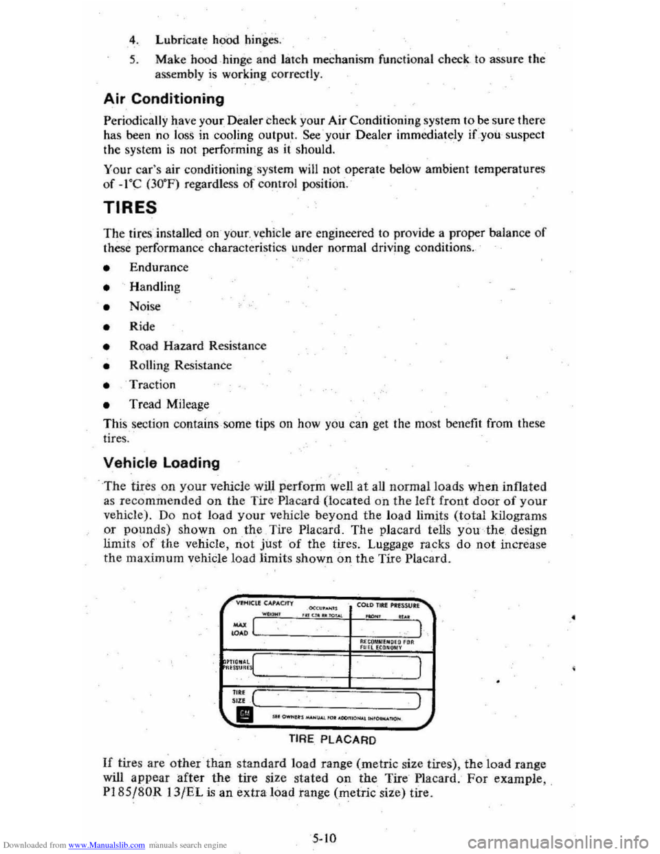
-The tires on yo ur vehicl e -wil) perform well at aU normal loads w hen inflated
as recommended on the Tire Placa rd (located on the left front d -odr of your
vehicle) . Do not load your vehicle beyond the load limit s (total kilograms
or pounds) shown on the Tire Plac ard. The pla card tells you the design
limit s 'of' the vehicle, not just 'of the tires. Luggage tacks do not increase the maxim um vehicle load limits shown on the Tire Placard.
COI.DJIU ... nWb. .n, ... ~ ... .""". .. ..
~LC-----------·--t,M.~ro""'''~,."."''~. 1 F"HEca.~Y
I
::;: ( ) "" II''--.-,----.. -,--"-~--_-_--.-_-, .-,-_--_--'...J.J
TIRE PLACARD
If tire s are other -than standard load range (metric size tires), the load range
will
appear after the tire size stated on the Tire Placard . For example , , PI8S j80R 13/EL is an extra load tange (metric size) tire.
5-10
.'