1980 CHEVROLET CITATION length
[x] Cancel search: lengthPage 13 of 95

Downloaded from www.Manualslib.com manuals search engine • In a single motion, pull the rear seat outboard lap belt across your lap far
enough to-push the latch plate into the buckle. un Iii it clicks._ If the belt is
not pulled out far enough to rcadi the-buckle, let the lap bell rewind fully
into its retractor. This unlocks
it so the belt can be puBed .out to the proper length .
• These belts should be positioned, worn, and released as described above under "Front Seat Lap~ShouJder Belt." After fastening, check that the belt is SNUG by pulling the belt firmly across', your lap toward the Jap belt retractor. This
will allow the retractor to take up slack.
• The lap belt at the center seat also should be positioned, worn, and relea sed
as described above-however , it does not have a retractor. It should be
adju sted 10 a SNUG FIT by pulling on the end of the belt coming from the
adju stable latch plate .
• To lengthen the center seat lap belt. place the latch plate at a right angle to
the belt webbing and pull on the latch plate. The belt should then slide easily.
Additional Rear Seat Shoulder Belts-Offerad as an
Accessory by Your Dealer
• When properly worn with a lap beh,--a -shoulder belt can give riders added
protection . II can prevent or reduce impact with the insides of the vehicle
'by restraining the upper body in a collision. This is especially true in a frontal
impact.
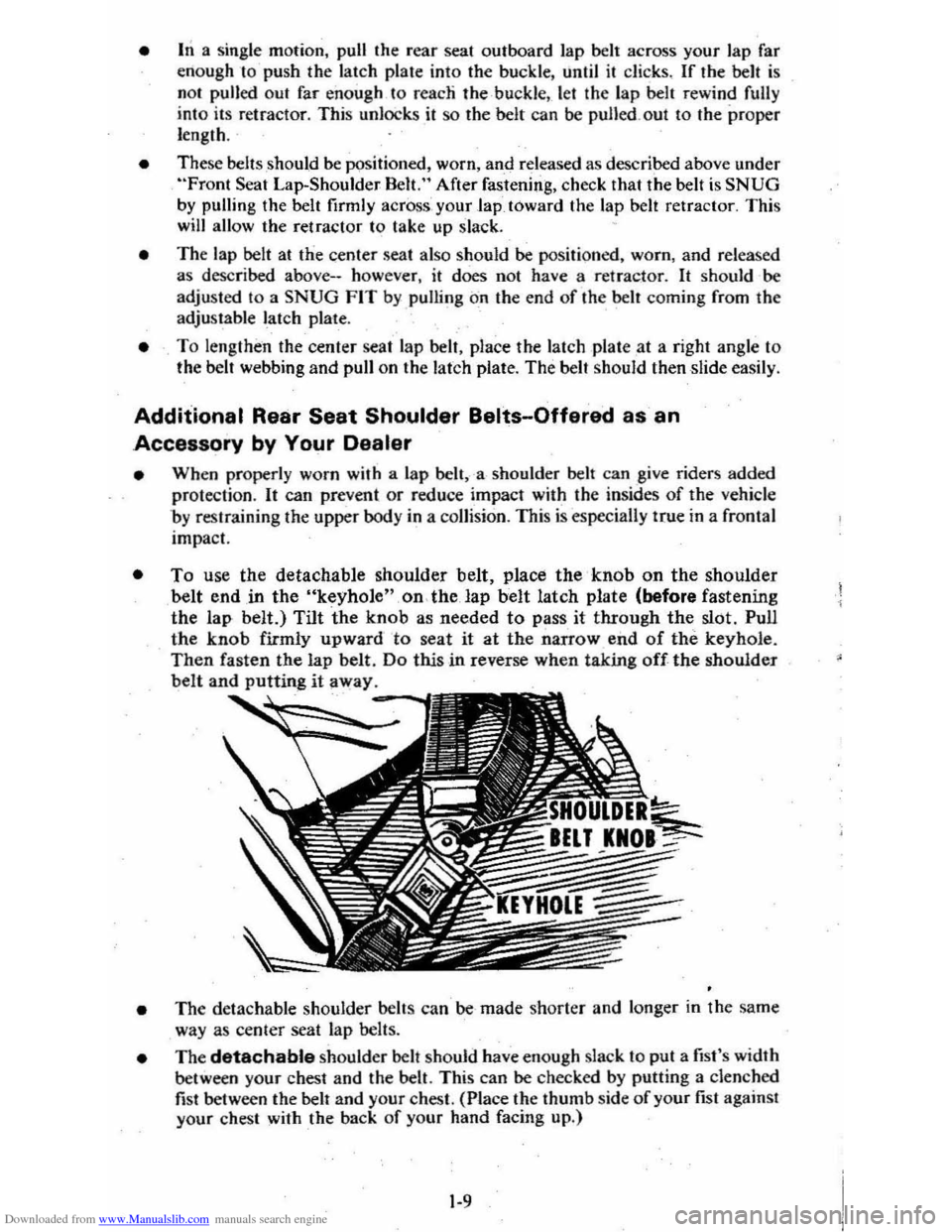
• To use the detachable shoulder belt. place the' knob on the shoulder belt end.in the "keyhole"on.the lap belt latch plate (before fastening
the lap belt.) Tilt the knob as needed
to pass it through the slot. Pull
the knob firmly upward to seat it at the narrow end of the keyhole. Then fasten the lap belt. Do this in reverse when taking off-the shoulder
belt and putting it away.
• The detachable shoulder belts can be made shorter and longer in the same
way as center seat lap belts .
• The detachable shoulder belt should have enough slack to put a fist's width
between your chest and the belt. This can be checked by putting a clenched
fist between the belt and your chest. (Place the thumb side of your fist against
your chest with the back of your hand facing up.)
1-9
Page 46 of 95

Downloaded from www.Manualslib.com manuals search engine Insta"ation
To install the cargo cover:
1. Insert the left hinge pin in the bracket attached to the body of the car.
2. Slide the release lever to the right to engage hinge pin in the 'bracket. See figure
B.
3. Move the lever up to lock the cover in place.
4. Reconnect the rubber 'lifting cords.
STOWING THINGS IN (OR ON) THE CAR
CAUTION: luggage or other cergo should not be piled higher than the seatbacks, When at all possible, luggage or cargo should be C8rrifHj in the trunk area. The filler panel or cargo cover, between the rear 88atback and the rear window should not be used to carry objects-even those that are small and light. All nems should be secured in place. This will help keep such things from being thrown about and Injurying people in the car during an accident. Cargo weight whether inside or on the roof, should be positioned as evenly as possible from front to rear.
ROOF LUGGAGE CARRIER
The optional roof luggage carrier is designed to allow loading of items onto the
roof
of your car. The roof luggage carrier does not increase the total load carrying
capacity of th e car , as shown opposite "Max Load" on the Tire Placard located
on the left front door. Be sure the total weight of the cargo on the roof, plus the
weight
of the cargo and passe ngers inside the car, plus the tongue load of any
trailer you are towing does
,1;10t exc_eed this "Max Load" vehicle capacity weight. See Section 5, page "5-11 for more information on Vehicle Loading . Also see the
infonnation on Trailer Towing
in Section 1 of this manual . if needed .
NOTICE:To helpayoid pOSSible damage, do not exceed 70 kilograms (1 50 pounds), cargo weight on the roof. Position the cargo in the luggage carrier as evenly as: pOssible. If carrying long items, never exceed car length and fasten such loads securely at the front and rear of the car, as well as to the luggage rack.
The roof luggage carrier consists of: five roof slats bolted to the top of the car,
two crossrails with knobs at each end th~t allow the crossrails to be adjusted or removed, and six' adjustable tie-downs.
The operation
of each item is as follows: the crossrails are easily adjusted forward
or rearward in order to help position your load. To move the crossrails , rotate
the large adjustable knob, ··No. 3" in the figure above. counterclockwise to loosen
(or remove) the crossrails and 'clockwise to tighten down the cros srails. Attached
to the top
of the crossrails are two adjustable tie-downs, "No.4" in the figure.
Ther e is also one adjustable lie-down located in the center of each outer roof slat
assembly (also called
"No.4" in the figure) . The tie-downs may be easily moved
forward and rearward within the outer slat assembly and across the top
of the
crossrails to the desired position.
To move the tie-down . rotate it countetclockwise
to loosen and clockwise to tighten down. If needed to sec ure a certain type of lead,
the tie-downs on the
crossratls may be removed and repos itioned on the outer roof
slat assemblies. While underway, periodically check to make sure that
the crossrails and the tie-downs are securely fastened to help
prevent loss of cargo, or the roof rack equipment itself.
The crossrails may be removed when not in use and stowed in the trunk or behind
the second seat on the rear load floor (with the carg o cover installed) in hatchback
style
s. When stowing the cressrails, al5..1 attach the tie-downs from the outer roof
2-29
Page 83 of 95

Downloaded from www.Manualslib.com manuals search engine . SECTION 7
SPECIFICATIONS
T hese specifications are given here for information on ly . B efore using them, see the cautions and other instructions
throughout this manual. For fu.rther information , see the
service manual covering the chassis or body part in question. Your Chevrol et dealer may also be abl e to help.
DIMENSIONS
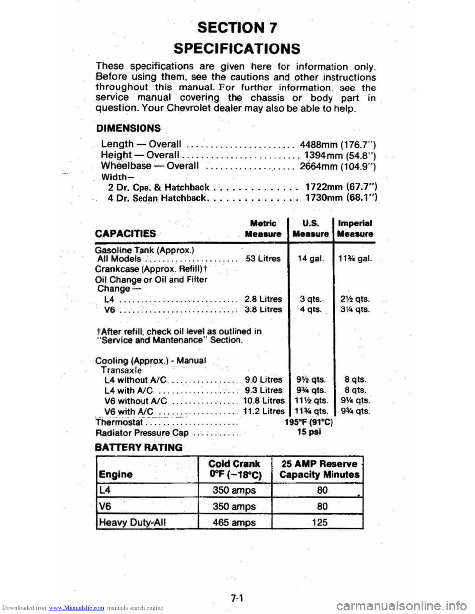
Length -Overall ......... , •.... , •...... 4488mm (176 .7")
He igl;lt -Overall ......................... ':394mm (54.8 ") Wh eelbase "-Overall ................... 2664mm (104.9")
Width-2 Dr. Cpe. & Hatchback .· ............. 1722mm (67.7") 4 Dr. Sedan Hatchback.. . . . . . . . . . . . .. 1730mm (68.1 ")
Metric U .S .
CAPACITIES Mea .... .... .ur.
Gasoline rank (Approx.) All Models .................... 53 litres 14 gal.
Crankcase (Approx . Refililt Oil Change or Oil and Filter Change-
L4 ........ ........... '. ' .. ... 2.8 Litres 3 qts .
V6 . . . . . , . . . . . . . . . . . . . . . . . . . . . . 3 :8 Litres 4 qt • . .
t After refill ; check oil kwel as outlined in "Service and Mantenance " Section .
Cooling (Approx.)· Manual Tran sa x le L4 without AlC ..... . , .. .
L4 withA/C .... ... ........... .
V6 without AlC ...... ...•...... V6 with AlC ....... . Thermostaf.-.-:~-~-. -....... : ....... .
Radiator Pressure Cap
BATTERY RATING
9.0 Litre. 911 •. qls. 9.3 Litres 9¥4 qts.
to.8 Litres 1'1'12 qts.
11.2 Litres 11¥ " .c:Jts. 195"1' (91·e) 15 pal
Imperial
Me.sure
11~gal.
21f2qts .
3Ve qts.
8 qt •.
8 qts. 9V .. qts.
g¥ .. qts.
colci Crank 25 AMP Reserve
Engine .. O"F (-l8"C) Capacity Minutes
L4 350 amps 60
V6 350 amps 80
Heavy Duty "AIi 465 amps 125
7-1