Page 529 of 548

rt
ASSEMBLY
1
Press
bearings
into
V
pulley
with
Bearing
Installer
5T0237
1000
51
02371000
AC503
Fig
AC
47
In
talling
Bearing
2
Install
outer
snap
ring
in
groove
of
V
pulley
3
Using
Installer
KV99l
0061
0
and
Stopper
ST33061000
press
clutch
wheel
into
V
pulley
4
Install
inner
snap
ring
in
groove
of
clutch
wheel
u
Installer
KV99100610
2
Stopper
ST33061000
AC504
Fig
AC
48
Installing
Clutch
Wheel
INSPECTION
I
Check
friction
surface
of
clutch
for
damage
due
to
excessive
heat
or
excessive
grooving
due
to
slippage
If
neceSS3I
replace
clutch
wheel
and
V
pulley
as
a
set
Air
Conditioning
2
The
clearance
between
V
pulley
and
clutch
wheel
should
be
0
4
to
0
6
mm
0
016
to
0
024
in
If
not
replace
clutch
wheel
assem
bly
3
Oil
or
dirt
on
friction
surfaces
of
clutch
wheel
and
V
pulley
should
be
cleaned
with
a
clean
Iint
free
clot
or
suitable
solvent
4
Check
coil
for
shorted
or
opened
lead
wire
Pay
particular
attention
to
grounding
part
of
coil
If
there
is
no
continuity
replace
electromagnetic
coil
Fig
AC
49
Grounding
Point
01
Coil
S
If
clutch
assembly
must
be
re
placed
remember
that
break
in
opera
tion
is
neceSS3I
The
break
in
opera
tion
consists
of
engaging
and
disen
gagingthe
clutch
some
tirty
tlines
SHAFT
SEAL
The
shaft
seal
assembly
of
this
compressor
is
of
a
simplified
design
yet
tight
sealing
and
long
lasting
REMOVAL
It
is
recommended
that
the
com
pressor
be
removed
from
the
car
for
shaft
seal
replacement
I
Remove
oil
filler
plug
with
O
ring
and
drain
the
compressor
oil
AC
28
AC393
Fig
AC
50
Removing
Filler
Plug
2
Remove
clutch
Refer
to
Com
pressor
Clutch
for
removal
3
Remove
shaft
key
from
crank
shaft
L
IJ
C
I
0
ACS07
Fig
AC
51
Removing
Shott
Key
4
Remove
seal
plate
J
e
I
@
IR
n
1
j
AC866
Fig
AC
52
Removing
Seal
Plote
5
With
Compressor
Seal
Puller
pull
out
seal
gland
and
discard
CAUTION
a
iscard
all
parts
of
he
seal
in
cluding
tha
O
ring
b
00
not
use
a
screwdrivel
to
pry
shaft
seal
from
shaft
as
damage
to
shaft
may
result
Page 530 of 548

AC867
Fig
AC
53
Removing
Shaft
Seal
INSTALLATION
1
Clean
shaft
and
seal
cavity
with
clean
lint
free
cloth
2
Dip
seal
gland
in
clean
refrigerant
oil
3
Push
seal
assembly
except
carbon
ring
over
end
of
shaft
with
carbon
ring
retainer
facing
out
4
Move
seal
assembly
into
position
on
shaft
ACB68
Fig
AC
54
1merting
Shaft
Seal
Assembly
5
Place
carbon
ring
in
ring
reta
iner
so
lapped
surface
is
facing
outward
Note
The
indentions
in
outside
edge
of
carbon
ring
must
engage
driving
lugs
and
be
rmnly
seated
in
re
tainer
6
Install
new
Q
ring
in
groove
of
seal
plate
Note
Use
refrigeration
oil
to
make
it
adhere
to
surface
Air
Conditioning
7
Space
seal
plate
with
equal
clear
ance
around
shaft
and
insert
cap
screws
Tighten
these
screws
evenly
IiJ
Tightening
torque
Seal
plate
securing
cap
screws
0
7
to
1
0
kg
m
5
1
to
7
2
ft
Ibl
AC869
Fig
AC
55
Spacing
Seal
Plate
and
Tightening
Cap
Screws
8
Install
clutch
Refer
to
Compres
sor
Clutch
for
installation
9
Charge
lubricant
To
Low
pressure
service
valve
10
Install
oil
filler
plug
together
with
O
ring
CAUTION
Use
new
O
ring
when
installing
oil
filler
plug
INSPECTION
Check
for
gas
leakage
as
follows
I
Plug
high
and
low
pressure
joints
on
compressor
with
blind
caps
2
Connect
charging
hoses
in
lines
between
manifold
gauge
and
high
and
low
pressure
service
valves
Connect
refrigerant
can
to
middle
hose
of
manifold
gauge
3
Open
valve
of
can
tap
and
charge
refrigerant
Loosen
oil
filler
plug
at
side
of
compressor
to
purge
air
out
of
compressor
4
Turn
shaft
5
or
6
turns
Then
confIrm
that
pressure
does
not
decrease
on
low
pressure
gauge
If
gauge
indicates
a
pressure
decrease
there
is
a
leak
Conduct
a
leak
test
Under
such
a
condition
remove
and
then
install
parts
again
To
High
pressure
service
valve
Low
r
fi
IZl
AC
29
High
AC183A
Fig
AC
56
Checking
for
Gas
Leakage
Page 531 of 548

r
CYLINDER
HEAD
AND
VALVE
PLATE
Insufficient
refrigerant
v
p
sion
is
likely
to
be
caused
by
damaged
head
gasket
or
damaged
valves
Prior
to
servicing
the
head
and
valve
plate
both
service
valves
should
be
opened
to
free
any
gas
pressure
which
may
be
in
the
compressor
REMOVAL
I
Remove
cylinder
head
securing
bolts
Fig
AC
57
Removing
Cylinder
Head
2
Remove
valve
plate
and
head
from
cylinder
by
prying
or
tapping
under
the
ears
which
extend
from
valve
plate
If
head
and
valve
plate
adhere
hold
head
and
tap
valve
plate
ears
away
from
head
with
a
soft
hammer
CAUTION
00
not
hit
or
llIp
head
to
separate
head
and
valve
plate
because
damage
to
head
may
result
AC871
Fig
AC
58
Removing
Volve
Plate
and
Head
3
When
removing
the
gaskets
use
a
sharp
edged
knife
Air
Conditioning
CAUTION
a
In
removing
head
gasket
be
very
careful
not
to
damage
machined
sealing
surface
b
00
not
reuse
gaskets
AC815
Fig
AC
59
Removing
Gasket
INSTALLATION
Valves
and
valve
plates
are
furnish
ed
only
as
a
complete
assembly
8
AC872
Fig
AC
60
Valve
Plate
Assembly
I
Apply
a
thin
mm
of
clean
refri
geration
oil
on
area
of
crankcase
to
be
covered
by
cylinder
gasket
Fig
AC
61
Applying
Clean
Refrigeration
Oil
AC
30
2
Place
cylinder
gasket
in
position
on
cylinder
so
dowel
pins
in
crankcase
go
through
dowel
pin
holes
in
cylinder
gasket
3
Apply
a
thin
flim
of
clean
refri
geralion
oil
to
top
and
bottom
valve
plate
areas
to
be
covered
by
gaskets
4
Place
valve
plate
in
position
on
cylinder
gasket
so
discharge
valve
as
semblies
I
e
smaller
diameter
assem
blies
with
restrainer
over
valve
reed
are
facing
up
and
locating
dowel
pins
go
through
dowel
pin
holes
in
valve
plate
AC817
Fig
AC
62
Placing
Valve
Plate
5
Place
head
gasket
in
position
on
valve
plate
so
dowel
pins
go
through
dowel
pin
holes
in
gasket
6
Apply
a
thin
mm
of
clean
refri
geration
oil
on
the
machined
surface
of
cylinder
head
which
matches
head
gasket
7
Place
head
on
cylinder
head
gas
ket
so
dowel
pins
go
into
dowel
pin
holes
in
head
8
Tighten
screws
to
specified
limit
iil
Tightening
torque
Cvlinder
head
screws
2
1
to
3
2
kg
m
15
to
23
ft
Ibl
DISCHARGE
AND
SUCTION
CONNECTORS
Discharge
and
suction
connectors
are
located
on
rear
side
of
compressor
Page 532 of 548
REMOVAL
1
Remove
each
screw
securing
dis
charge
and
suction
connectors
using
TOD
Driver
Bit
2
Pull
out
each
discharge
and
suc
tion
connector
Note
Memorize
mounted
direction
of
discharge
and
suction
connectors
to
ensure
correct
reassembling
a@
AC873
Fig
AC
63
Removing
Discharge
and
Suction
Connectors
Air
Conditioning
INSTALLATION
I
Attach
new
O
ring
to
each
cy
lindrical
portion
of
discharge
and
suc
tion
valves
Note
Apply
clean
lubricant
to
O
ring
so
that
it
can
be
fitted
tightly
to
cylindrical
portion
and
crankcase
hole
AC
31
2
Insert
each
discharge
and
suction
valves
into
correct
valve
port
in
crank
case
by
matching
it
with
mark
on
cylinder
head
3
Set
each
valve
in
the
same
posi
tion
as
it
was
before
removal
and
tighten
screws
with
specified
torque
cD
Tightening
torque
Discharge
and
suction
connectors
2
1
to
3
2
kg
m
15
to
23
ft
b
Page 533 of 548

Com
pressor
OFF
I
I
Blower
makes
noise
Repair
or
re
place
blower
Bearings
of
com
pressor
clutch
or
idler
pulley
make
noise
Replace
C
l
W
Noisy
Compressor
itself
makes
noise
Repair
or
replace
com
pressor
Belt
is
loose
Adjust
belt
Suction
pressure
is
low
Strainer
in
pipe
Line
Is
restricted
Replace
strainer
Pipe
at
receiver
drier
outlet
has
low
temperature
Receiver
drier
is
restricted
Replace
receiver
drier
I
Fin
and
tube
of
evaporator
or
laminated
evapo
rator
have
some
dents
Replace
or
repair
evaporator
Expansion
valve
is
close
excessively
or
gas
leakage
from
thermo
bulb
Replace
expansion
valve
Compressor
ON
J
I
When
engine
rpm
is
changed
there
are
reso
nant
sounds
Retighten
com
pre
ssor
bracket
bolts
Piping
is
reso
nating
Add
clamp
Insufficient
cooling
Bubbles
in
sight
glaS
Check
refrigeration
line
for
gas
leaks
and
repair
leaks
if
any
Charge
re
frigerant
to
correct
level
In
case
of
too
many
leaks
stop
com
pressor
discharge
the
system
evaCUate
and
recharge
the
system
As
necessary
replace
receiver
drier
Air
in
system
may
cause
bubbles
in
sight
glass
System
pressure
and
temperature
of
discharge
air
llre
abnormal
Refer
to
Performance
Test
Diagnoses
for
detail
Suction
pres
sure
is
high
Expansion
valve
is
open
excessively
Replace
ex
pansion
valve
Discharge
pressure
is
high
Overcharge
of
refrigerant
Discharge
some
of
refrig
erani
to
correct
level
Air
is
mixed
in
Discharge
system
and
replace
drier
Evacuate
and
recharge
system
Condenser
s
fin
is
dented
or
clogged
with
dust
Clean
exterior
surface
with
water
No
bubbles
in
sight
glass
With
manifold
gauge
check
system
pres
sures
Measure
tem
perature
of
discharge
air
Refer
to
Perform
ance
Test
Blower
does
not
rotate
Refei
to
Blower
Motor
Diagnoses
Temperature
of
discharge
air
is
abnormal
but
system
pres5ure
is
normal
Suction
pressure
iJ
high
while
dis
charge
pressure
is
low
Valve
or
gasket
of
compressor
is
damaged
Repair
or
replace
compreuor
Check
air
flow
system
Refer
to
Air
Conditioner
Operation
Chart
Compressor
does
not
run
Refer
to
Com
pressor
Diagnoses
Check
grommets
on
car
s
dash
panel
for
air
leaks
check
other
seal
of
car
Page 534 of 548
Air
Conditioning
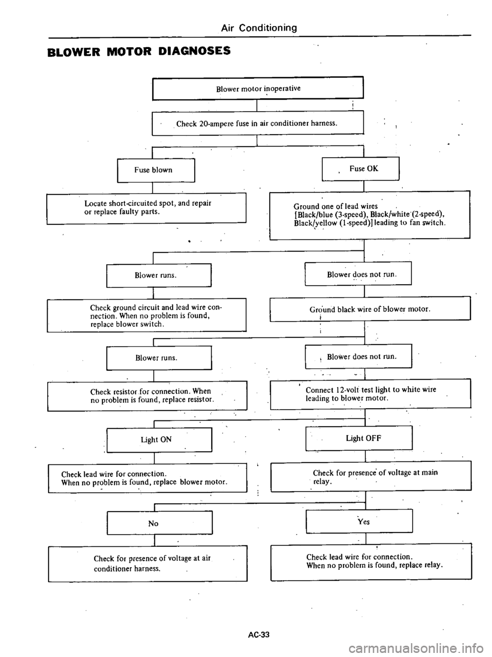
BLOWER
MOTOR
DIAGNOSES
I
Blower
motor
inoperative
I
Check
20
ampere
fuse
in
air
conditioner
harness
Fuse
blown
Fuse
OK
Locate
short
circuited
spot
and
repair
or
replace
faulty
parts
Ground
one
of
lead
wires
Black
blue
3
speed
Black
white
2
speed
Black
yellow
l
speed
1eading
to
fan
switch
Blower
runs
Blower
does
not
run
Check
ground
circuit
and
lead
wire
con
oeetion
When
no
problem
is
found
replace
blower
switch
Ground
black
wire
of
blower
motor
i
Blower
runs
Blower
does
not
run
Check
resistor
for
connection
When
no
problem
is
found
replace
resistor
Connect
12
volt
test
light
to
white
wire
leading
to
blower
motor
Light
ON
Light
OFF
Check
lead
wire
for
connection
When
no
problem
is
found
replace
blower
motor
Check
for
presence
of
voltage
at
main
relay
No
Yes
Check
for
presence
of
voltage
at
air
conditioner
harness
Check
lead
wire
for
connection
When
no
problem
is
found
replace
relay
AC
33
Page 535 of 548

J
COnlp
reSSOI
clutch
is
not
J
engaged
c
00
ha
voltage
decreased
to
es
thall
lO
5V
Lead
wire
or
com
pressor
clutch
is
dead
I
Ground
terminal
of
coil
is
poor
a
t
connection
Repair
connection
Refer
to
CompreSior
Clutch
Diagnoses
J
J
r
In
c
e
Clutch
is
not
en
gaged
yet
replace
compressor
dutch
lr1
vetChatgO
of
Ief
ge1ant
I
I
e
refrigotant
gas
10
n
o
t
cnt
j
that
sight
gla
ss
of
receiver
drier
has
onlY
a
few
bubble
Engine5peed
l
OOrpm
i
l
r
Check
for
dis
charge
pressure
OK
if
dbcnarge
pres
ure
is
reduced
Discharge
pres
sure
is
not
reduced
l
Compressor
clutch
is
engaged
but
compre
sor
doe
not
IUn
Cbeck
and
re
adjust
gap
of
clutch
Clea
Il
oil
OJ
dust
on
contact
sur
face
of
clutch
if
slipping
con
ti
n
ues
rCPlaO
J
compressor
clutch
Check
belt
teMion
and
adjust
it
lfbelt
bwor
l
out
or
damaged
ie
pl
ce
iI
Air
in
refrigeration
System
J
Discharge
system
ftom
service
valve
on
discharge
side
Evacuate
a
nd
rech
arge
the
Lystem
J
When
torque
is
stm
grellt
repair
or
rtV1ace
compressor
j
T
son
rod
l
mp
teSSOI
j
Internal
problem
in
cornpre
sor
cyl
inder
Check
y
tem
Repau
or
replace
nece
tY
J
r
Compte
r
oille
ing
J
Air
blOW
on
spot
whcre
oil
leak
e
vidence
is
round
Then
check
for
refrigerant
leakS
us
n
leak
detectof
Refrigerant
leaking
Repau
01
replace
compttUOr
I
NO
teftig
lea
ing
Wipe
clean
oil
wi
h
Jag
L
Noisy
onlY
when
clutch
is
engaged
Check
for
oo
c
comprenor
mount
ing
Dolts
Retighten
bolts
Compressor
drive
belt
islOosc
Adjust
belt
ttM1on
If
cotTlpre
sor
is
noisY
yet
repair
or
replace
compres
sor
Noisy
when
clutch
is
not
engaged
Remove
cQm1JressOt
belL
Turn
pulley
of
compressot
clutch
by
hand
and
check
for
noise
If
noisC
is
MaId
repair
com
preM
or
clutCh
01
o
B
0
a
Ut
Ut
o
a
a
i
o
Ut
A
o
l
Cl
o
l
l
tC
Page 536 of 548

Air
Conditioning
COMPRESSOR
CLUTCH
DIAGNOSES
Compressor
clutch
is
not
engaged
Check
20
arnpere
fuse
in
air
conditioner
harness
Fuse
blown
Fuse
OK
Locate
short
circuited
spot
and
repair
or
replace
damaged
parts
Connect
12
volt
test
light
to
compressor
clutch
lead
wire
Ground
the
other
end
of
test
light
Set
air
control
lever
to
A
C
posi
tion
Light
ON
Light
OFF
I
Check
low
pressure
switch
for
continuity
L
H
drive
only
Check
lead
wire
and
ground
wire
of
compres
sor
clutch
for
connection
When
there
is
nothing
wrong
with
them
replace
compressor
clutch
No
I
Yes
Measure
pressure
in
system
If
there
is
a
leak
service
system
If
pressure
is
normal
check
low
pressure
switch
as
a
part
reo
place
if
necessary
Connect
12
volt
test
light
to
terminal
of
blue
green
wire
leading
to
thermostat
Ground
the
other
end
of
test
light
Light
ON
Light
OFF
Check
ground
circuit
and
make
sure
of
proper
connection
Further
check
lead
wire
connection
and
when
no
problem
is
found
replace
air
conditioner
harness
or
main
harness
Connect
12
volt
test
light
to
blue
white
wire
of
microswitch
Ground
the
other
end
of
test
light
I
Light
ON
I
Light
OFF
I
Check
lead
wire
connection
When
no
problem
is
found
replace
thermostat
Check
for
current
flow
in
lead
wire
to
main
relay
Yes
I
I
No
Check
lead
wire
for
connection
When
no
problem
is
found
replace
microswitch
or
main
relay
Check
power
supply
AC
35