Page 466 of 513
ENGINE
REMOVAL
INSTAllATION
Fig
ER
5
Rear
mounting
4
Remove
four
bolts
and
separate
the
insulator
from
the
engine
mount
member
Reinstallation
Reinstall
the
rear
engine
mounting
in
reverse
sequence
of
removal
noting
the
following
matters
I
Tighten
the
nuts
and
bolts
correctly
and
securely
Lp
FRONT
FOR
MANUAL
TRANSMISSION
Nut
@
mount
member
insulator
Nut
@@
transmission
insulator
Bolt
CD@
mount
member
body
Tightening
torque
kg
m
ft
Ib
0
6
to
0
8
4
3
to
5
8
1
9
to
2
6
l3
to
18
8
3
2
to
4
0
23
1
to
28
9
Fig
ER
6
Rear
mounting
installation
2
Carefully
arrange
the
front
and
rear
directions
of
the
rear
engine
mounting
when
installing
tp
FRONT
FOR
AUTOMATIC
TRANSMISSION
Fig
ER
7
R
ar
mounting
specifications
ER
3
Page 468 of 513
ENGINE
REMOVAL
INSTAllATION
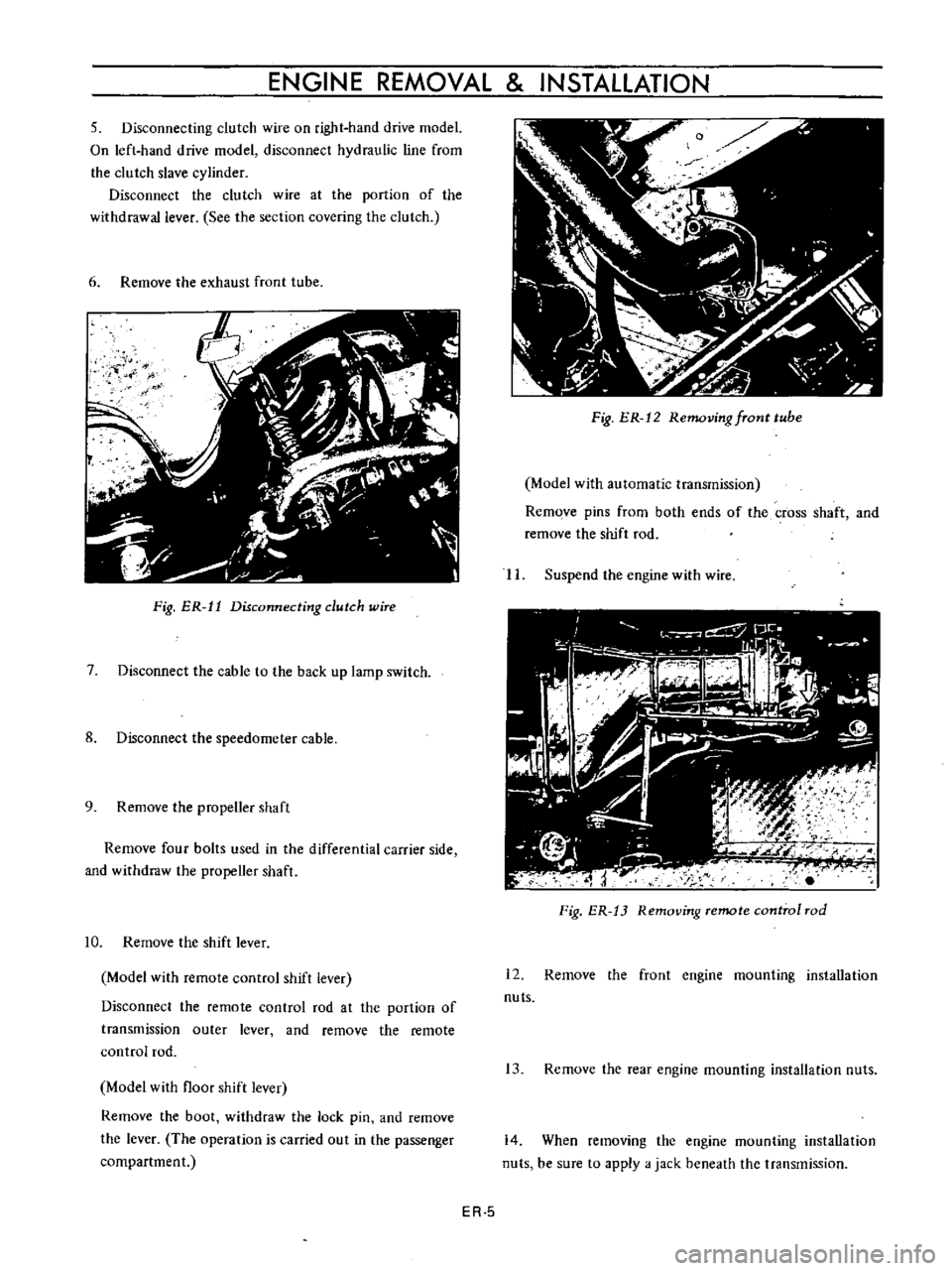
5
Disconnecting
clutch
wire
on
right
hand
drive
model
On
left
hand
drive
model
disconnect
hydraulic
line
from
the
clutch
slave
cylinder
Disconnect
the
clutch
wire
at
the
portion
of
the
withdrawal
lever
See
the
section
covering
the
clutch
6
Remove
the
exhaust
front
tube
ij
f
I
Fig
ER
11
Disconnecting
dutch
wire
7
Disconnect
the
cable
to
the
back
up
lamp
switch
8
Disconnect
the
speedometer
cable
9
Remove
the
propeller
shaft
Remove
four
bolts
used
in
the
differential
carrier
side
and
withdraw
the
propeller
shaft
10
Remove
the
shift
lever
Model
with
remote
control
shift
lever
Disconnect
the
remote
control
rod
at
the
portion
of
transmission
outer
lever
and
remove
the
remote
control
rod
Model
with
floor
shift
lever
Remove
the
boot
withdraw
the
lock
pin
and
remove
the
lever
The
operation
is
carried
out
in
the
passenger
compartment
Fig
ER
12
Removing
fTont
tube
Model
with
automatic
transmission
Remove
pins
from
both
ends
of
the
cross
shaft
and
remove
the
shift
rod
II
Suspend
the
engine
with
wire
Fig
ER
13
Removing
remote
control
rod
12
Remove
the
front
engine
mounting
installation
nuts
13
Remove
the
rear
engine
mounting
installation
nuts
14
When
removing
the
engine
mounting
installation
nuts
be
sure
to
apply
a
jack
beneath
the
transmission
ER
5
Page 503 of 513
CHASSIS
REINSTALLATION
Remount
the
transmission
in
reverse
sequence
of
dismounting
TRANSMISSION
GEAR
CONTROL
CONTENTS
DESCRIPTION
COLUMN
SHIFT
CONTROL
SYSTEM
Removal
TM
16
TM
17
TM
17
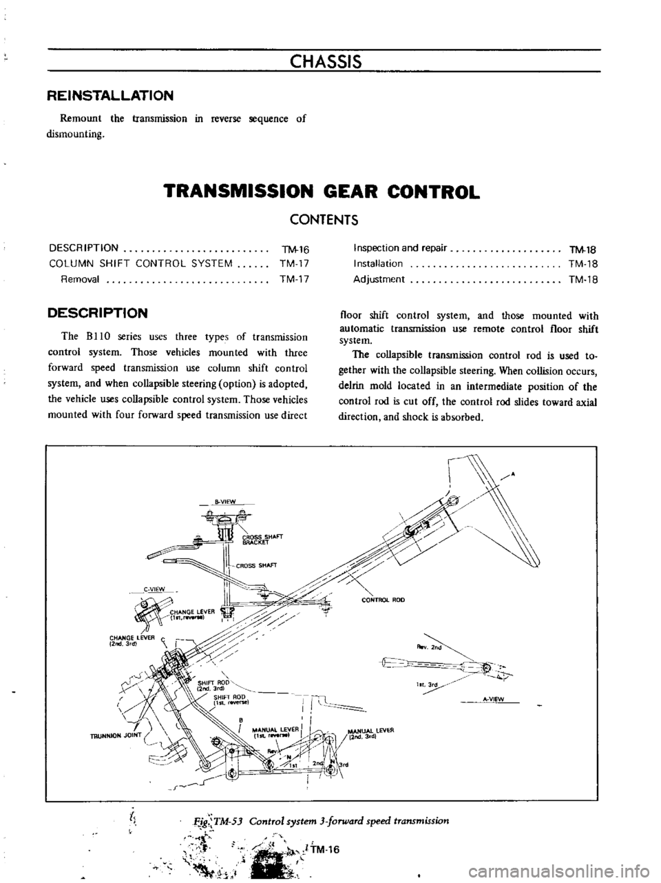
DESCRIPTION
The
B
10
series
uses
three
types
of
transmission
control
system
Those
vehicles
mounted
with
three
forward
speed
transmission
use
column
shift
control
system
and
when
collapsible
steering
option
is
adopted
the
vehicle
uses
collapsible
control
system
Those
vehicles
mounted
with
four
forward
speed
transmission
use
direct
B
VIEW
CROSS
SHAFT
BRACKET
CROSS
SHAfT
C
VIEW
HANGE
LEVER
l
rwIl
CHANGE
LEVER
C
2
3rdl
r
X
h
Inspection
and
repair
Installation
Adjustment
TM
18
TM
18
TM
18
floor
shift
control
system
and
those
mounted
with
automatic
transmission
use
remote
control
floor
shift
system
The
collapsible
transmission
control
rod
is
used
to
gether
with
the
collapsible
steering
When
collision
occurs
delrin
mold
located
in
an
intermediate
position
of
the
control
rod
is
cut
off
the
control
rod
slides
toward
axial
direction
and
shock
is
absorbed
c
0
CONTROL
ROD
r
A
v
t
c
t
IT
Ii
A
VIEW
MANUAL
LEVER
II
l
MANUAl
lEVER
11st
r
lW1
11nd3rd
IIooV
j
II
1
0SI
2nd
Jrd
I
I
j
tl
Control
system
3
forward
speed
transmission
Ffg
TM
53
t
f
Voo
1
ITM
16
