Page 200 of 513
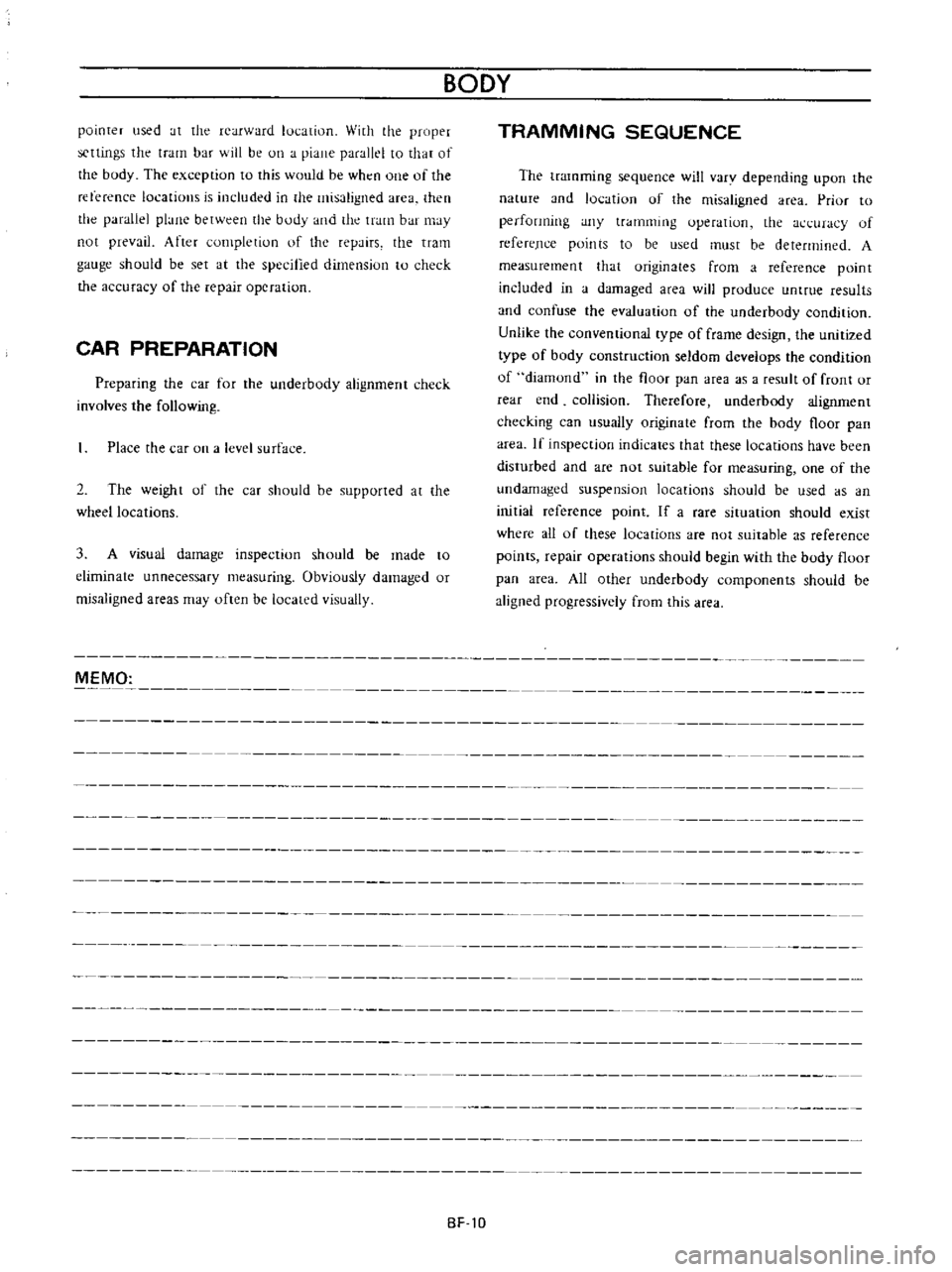
pointer
used
at
the
rearward
lut
atiol1
With
the
proper
scttings
the
tram
bar
will
be
on
a
piane
parallel
to
that
of
the
body
The
exception
to
this
would
be
wht
n
one
of
the
reterence
locations
is
induded
in
the
misaligned
area
then
the
parallel
plane
between
the
body
and
the
tram
bar
may
not
prevail
After
completiun
of
the
repairs
the
tram
gauge
should
be
set
at
the
specitled
dimension
to
check
the
accuracy
of
the
repair
operation
CAR
PREPARATION
Preparing
the
car
for
the
underbody
alignment
check
involves
the
following
Place
the
car
on
a
level
surface
2
The
weight
of
the
car
should
be
supported
at
the
wheel
locations
3
A
visual
damage
inspection
should
be
made
to
eliminate
unnecessary
measuring
Obviously
damaged
or
misaligned
areas
may
often
be
located
visually
BODY
TRAMMING
SEQUENCE
The
tramming
sequence
will
varv
depending
upon
the
nature
and
IOl
atiun
uf
the
misaligned
area
Priur
to
performing
any
tramming
uperation
the
h
uracy
of
refereJlce
points
to
be
used
must
be
determined
A
measurement
that
originates
from
a
reference
point
included
in
a
damaged
area
will
produce
untrue
results
and
confuse
the
evaluation
of
the
underbody
condition
Unlike
the
conventional
type
of
frame
design
the
unitized
type
of
body
construction
seldom
develops
the
condition
of
diamond
in
the
floor
pan
area
as
a
result
of
front
or
rear
end
collision
Therefore
underbody
alignment
checking
can
usually
originate
from
the
body
floor
pan
area
If
inspection
indicates
that
these
locations
have
been
disturbed
and
are
not
suitable
for
measuring
one
of
the
undamaged
suspension
locations
should
be
used
as
an
initial
reference
point
If
a
rare
situation
should
exist
where
all
of
these
lucalions
are
not
suitable
as
reference
points
repair
operations
should
begin
with
the
body
floor
pan
area
All
other
underbody
components
should
be
aligned
progressively
from
this
area
MEMO
BF
10
Page 483 of 513
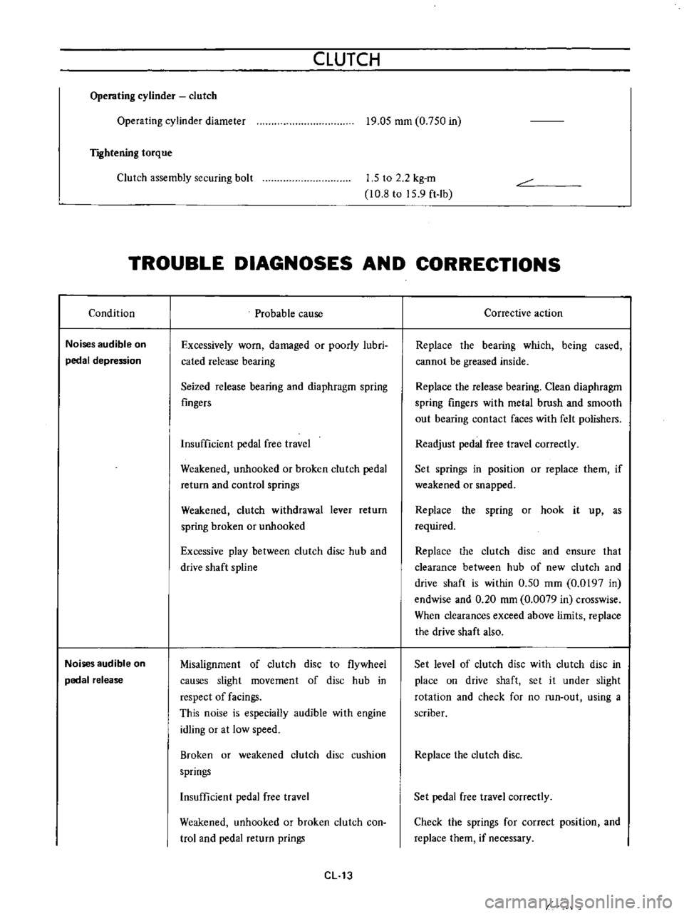
CLUTCH
Operating
cylinder
clutch
Operating
cylinder
diameter
T
Ilhtening
torque
19
05
mm
0
750
in
Clutch
assembly
securing
bolt
1
5
to
2
2
kg
m
10
8
to
15
9
ft
Ib
TROUBLE
DIAGNOSES
AND
CORRECTIONS
Condition
Noises
audible
on
pedal
depression
Noises
audible
on
pedal
release
Probable
cause
Excessively
worn
damaged
or
poorly
lubri
cated
release
bearing
Seized
release
bearing
and
diaphragm
spring
fingers
Insufficient
pedal
free
travel
Weakened
unhooked
or
broken
clutch
pedal
return
and
control
springs
Weakened
clutch
withdrawal
lever
return
spring
broken
or
unhooked
Excessive
play
between
clutch
disc
hub
and
drive
shaft
spline
Misalignment
of
clutch
disc
to
flywheel
causes
slight
movement
of
disc
hub
in
respect
of
facings
This
noise
is
especially
audible
with
engine
idling
or
at
low
speed
Broken
or
weakened
clutch
disc
cushion
springs
Insufficient
pedal
free
travel
Weakened
unhooked
or
broken
clutch
con
trol
and
pedal
return
prings
CL
13
Corrective
action
Replace
the
bearing
which
being
cased
cannot
be
greased
inside
Replace
the
release
bearing
Clean
diaphragm
spring
fingers
with
metal
brush
and
smooth
out
bearing
contact
faces
with
felt
polishers
Readjust
pedal
free
travel
correctly
Set
springs
in
position
or
replace
them
if
weakened
or
snapped
Replace
the
spring
or
hook
it
up
as
required
Replace
the
clutch
disc
and
ensure
that
clearance
between
hub
of
new
clutch
and
drive
shaft
is
within
0
50
mm
0
0197
in
endwise
and
0
20
mm
0
0079
in
crosswise
When
clearances
exceed
above
limits
replace
the
drive
shaft
also
Set
level
of
clutch
disc
with
clutch
disc
in
place
on
drive
shaft
set
it
under
slight
rotation
and
check
for
no
run
out
using
a
scriber
Replace
the
clutch
disc
Set
pedal
free
travel
correctly
Check
the
springs
for
correct
position
and
replace
them
if
necessary
Page 485 of 513
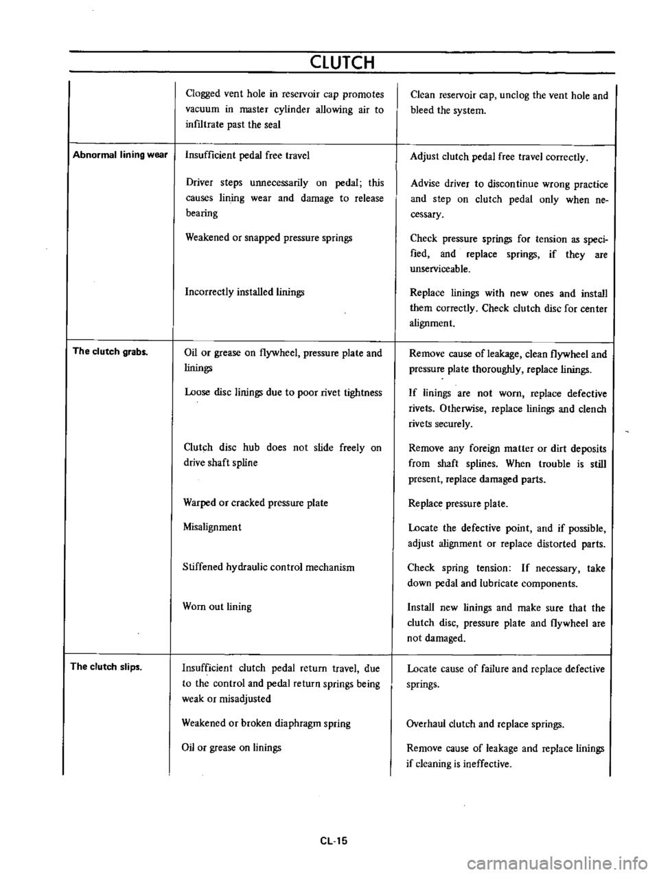
CLUTCH
Clogged
vent
hole
in
reservoir
cap
promotes
vacuum
in
master
cylinder
allowing
air
to
inf1ltrate
past
the
seal
Abnormal
lining
wear
Insufficient
pedal
free
travel
The
clutch
grabs
The
clutch
slips
Driver
steps
unnecessarily
on
pedal
this
causes
lin
jog
wear
and
damage
to
release
bearing
Weakened
or
snapped
pressure
springs
Incorrectly
installed
linings
Oil
or
grease
on
flywheel
pressure
plate
and
linings
Loose
disc
linings
due
to
poor
rivet
tightness
Clutch
disc
hub
does
not
slide
freely
on
drive
shaft
spline
Warped
or
cracked
pressure
plate
Misalignment
Stiffened
hydraulic
control
mechanism
Wom
out
lining
Insufficient
clutch
pedal
return
travel
due
to
the
control
and
pedal
return
springs
being
weak
or
misadjusted
Weakened
or
broken
diaphragm
spring
Oil
or
grease
on
linings
eLl5
Clean
reservoir
cap
unclog
the
vent
hole
and
bleed
the
system
Adjust
clutch
pedal
free
travel
correctly
Advise
driver
to
discontinue
wrong
practice
and
step
on
clutch
pedal
only
when
ne
cessary
Check
pressure
springs
for
tension
as
speci
fied
and
replace
springs
if
they
are
unserviceable
Replace
linings
with
new
ones
and
install
them
correctly
Check
clutch
disc
for
center
alignment
Remove
cause
of
leakage
clean
flywheel
and
pressure
plate
thoroughly
replace
linings
If
linings
are
not
worn
replace
defective
rivets
Otherwise
replace
linings
and
clench
rivets
securely
Remove
any
foreign
matter
or
dirt
deposits
from
shaft
splines
When
trouble
is
still
present
replace
damaged
parts
Replace
pressure
plate
Locate
the
defective
point
and
if
possible
adjust
alignment
or
replace
distorted
parts
Check
spring
tension
If
necessary
take
down
pedal
and
lubricate
components
Install
new
linings
and
make
sure
tha
t
the
clutch
disc
pressure
plate
and
flywheel
are
not
damaged
Locate
cause
of
failure
and
replace
defective
springs
Overhaul
clutch
and
replace
springs
Remove
cause
of
leakage
and
replace
linings
if
cleaning
is
ineffective
Page:
< prev 1-8 9-16 17-24