Page 35 of 513
AUTOMATIC
TRANSMISSION
1
range
Low
gear
Lo
Rev
B
k
Brat
Oownthift
SolenoOCl
14
T
COUP
A
uu
e
IV
hl
I
R
L
ub
c
tlon
Dr
n
It
Val
9
10
v
nHOI
V
l
in
jl
8
Sale
d
QI
Cow
ilt
V
D
nV
Front
Lubtlc
t
Oritice
ChotCk
Valv
I
I
14
Throttle
Dr
V
lv8
I
Pre
Modil
lv8
15
3
151
2nd
j
Pre
u
Re1julato
Valva
@
n
No
Marked
er
0
8in
Primary
Gove
nor
V
I
Line
p
Go
erno
feed
p
euu
GOvernor
preuu
lEII
IIIII
To
que
con
8
t8
pres
He
Th
ottl
p
Second
Go
l
Io
vel
8
Fig
A
T
45
Oil
pressure
circuit
diagram
11
range
Low
gear
AT
31
Page 36 of 513
CHASSIS
1
rang
nd
gear
rOto
Con
I
Fro
l
ubHCll
II
1
Y
I
W
t
I
r
G
p
u
Reg
lle10
Ve
O
II
F
onl
Clutch
L
0Yw
r
e
e
e
a
eke
I
v
Th
o
Vel
O
f
e
ell
II
Vel
ThrOttle
0
v
31
J
lI
2
P
MP
M
lc
I
10
JCJ
rll
ZZ
I
IS
@2nd
3tdTlm
1J
V
h
@2nd3
d
ShIff
V
2
N
t
it
S
Of
d
L
ock
V
h
3
I
12
3
ht
2nd
6
6
lL
II
g
Mon
V
I
I
III
lIA
k
t
O
in
Hf
i
P
y
Gov
no
Vel
e
L
ne
pr
Go
no
feed
gt
Hu
ecOncl
y
00
0
Vel
Go
no
p
us
ur
TO
Qu
cony
g
Th
onlepr
swr
Fig
A
T
46
Oil
pressure
circuit
diagram
Iz
range
2nd
gear
AT
32
Page 223 of 513
BODY
REAR
WINDOW
ELECTRIC
DEFROSTER
Option
J
Instrument
harness
Cooler
terminal
J
1
1
c
BW
Ignition
switch
I
lOA
@
hi
u
Heat
wire
glass
switch
T
Fig
BF
62
Wiring
diagram
The
rear
window
electric
defroster
glass
is
furnished
as
an
optional
equipment
It
is
semi
tempered
and
has
electric
heat
wires
baked
to
make
the
rear
window
glass
clear
under
adverse
weather
conditions
The
heat
wire
glass
switch
and
pilot
larnp
are
located
on
the
left
hand
side
of
the
instrument
as
shown
in
Figure
BF
64
Fig
BF
63
Heat
absorbing
rear
glass
Fig
HF
64
Location
of
heat
wire
glass
switch
and
pilot
lamp
3
Fig
BF
65
Front
floor
wiring
BF
33
Page 236 of 513
BODY
ELECTRICAL
WIRING
CONTENTS
WIRING
HARNESS
Engine
compartment
harness
I
nstrument
harness
BE
1
BE
1
BE
2
WIRING
HARNESS
The
wiring
harness
is
classified
into
engine
compart
ment
harness
instrument
harness
and
body
harness
The
individual
harness
Jocating
positions
and
connecting
Position
e
w
the
individual
wiring
harnesses
are
indicated
a
f
Moreover
for
the
body
harness
the
installing
positioJ
differ
mutually
in
Sedan
Coupe
Station
wagon
and
yan
Engine
compartment
harness
Fig
BE
1
Engine
compartment
harness
1
Body
harness
WI
RING
DIAGRAM
INSPECTION
BE
2
BE
4
BE
6
A
0
Ij
7
9
Fig
BE
2
Engine
compartment
harness
2
Fig
BE
3
Engine
compartment
harness
3
BE
1
Page 241 of 513

INSPECTION
Referring
to
the
wiring
diagram
check
the
wiring
harness
for
connection
with
electrical
equipment
and
connector
for
conned
ion
and
installation
When
checking
the
wiring
harness
note
the
following
matters
Connected
unit
should
not
be
loose
rusted
or
contaminated
2
Cable
insulator
cover
should
not
be
damaged
crack
ed
or
insulating
material
should
not
be
deteriorated
3
For
those
parts
which
are
grounded
through
the
installation
bolts
the
bolts
should
be
in
contact
with
the
body
completely
so
that
continuity
is
provided
in
between
the
body
and
bolts
4
Terminals
of
unit
through
which
current
flows
should
not
come
into
contact
with
other
metal
parts
5
No
erroneous
connection
should
be
present
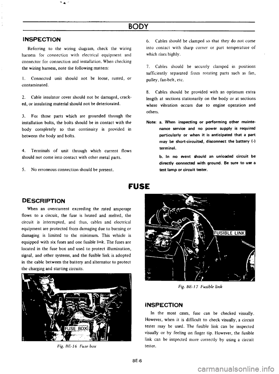
DESCRIPTION
When
an
overcunent
exceeding
the
rated
amperage
flows
to
a
circuit
the
fuse
is
heated
and
melted
the
circuit
is
interrupted
and
thus
cables
and
electrical
equipment
are
protected
from
damaging
due
to
burning
or
damaging
is
limited
to
the
minimum
This
vehicle
is
equipped
with
six
fuses
and
one
fusible
link
The
fuses
are
located
in
the
fuse
box
and
used
to
protect
illumination
signal
and
other
systems
and
the
fusible
link
is
adopted
in
the
cable
between
the
battery
and
alternator
to
protect
the
charging
and
starting
circuits
FiJ
BE
16
Fuse
box
BODY
6
Cables
should
be
damped
so
that
they
do
not
come
into
contact
with
sharp
corner
or
part
lernperature
of
which
rises
highly
7
Cables
should
be
securely
clamped
in
posItions
sufficiently
separated
from
rotating
parts
such
as
fan
pulley
fan
belt
etc
8
Cables
should
be
provided
with
an
optimum
extra
length
at
sections
stationarity
on
the
body
or
at
sections
where
vibration
occurs
due
to
engine
operation
and
others
Note
a
When
inspecting
or
performing
other
mainte
nance
service
and
no
power
supply
is
required
particularly
or
when
it
is
anticipated
that
a
part
may
be
short
circuited
disconnect
the
battery
H
terminal
b
In
no
event
should
an
unloaded
circuit
be
directly
connected
with
ground
Be
sure
to
use
a
test
lamp
or
circuit
tester
fUSE
Fig
BE
17
Fusible
link
INSPECTION
In
the
most
cases
fuse
can
be
checked
visually
However
when
it
is
difficult
to
check
visually
a
circuit
tester
may
be
used
The
fusible
link
can
be
inspected
visually
or
by
feeling
on
finger
tip
However
the
fusible
link
can
be
inspected
more
correctly
by
using
a
circuit
tester
BE
6
Page 246 of 513

BODY
ELECTRICAL
8
G
J
r
ICENSE
LAMPS
10
0
I
I
g
N
Ap
KING
10
00
01
2
I
NATION
J
J
r
j
a
iii
a
g
Lv
F
a
G
G
Lo
o
0
I
I
m
L
J
HER
UNIT
DIMMER
SWITCH
TURN
SIONAl
SWITCH
I
I
Fig
BE
28
Circuit
diagram
for
turn
signal
and
dimmer
switch
system
LIGHTING
SWITCH
HAZARD
WARNING
SWITCH
Removal
The
hazard
lamp
system
4
way
flasher
consists
of
hazard
warning
switch
and
flasher
unit
When
the
hazard
warning
switch
is
turned
on
all
signal
lamps
flash
simultaneously
telling
other
drivers
that
the
vehicle
is
stopped
When
the
turn
signal
lamps
flash
the
pilot
lamps
on
the
instrument
panel
also
flash
telling
you
of
hazard
lamp
operation
1
Rernove
the
connector
from
back
of
the
lighting
switch
2
Depressing
the
lighting
switch
knob
turn
it
counter
clockwise
and
remove
it
3
Loosen
the
escutcheon
switch
frorn
the
cluster
lid
and
remove
the
lighting
IGNITION
SWITCH
EZ
L
I
U
I
JJ
u
HAZARD
UNIT
Ip
FLASHER
UNIT
HAZARD
WARNING
SWITCH
161
6
6
g
Q
a
ll
Zll
Zll
CE
O
a
We
a
l
e
rY
1
LEFT
SiDE
RIGHT
SIDE
Fig
BE
29
Circuit
diagram
for
hazard
lamp
system
BE
11
Page 247 of 513

BODY
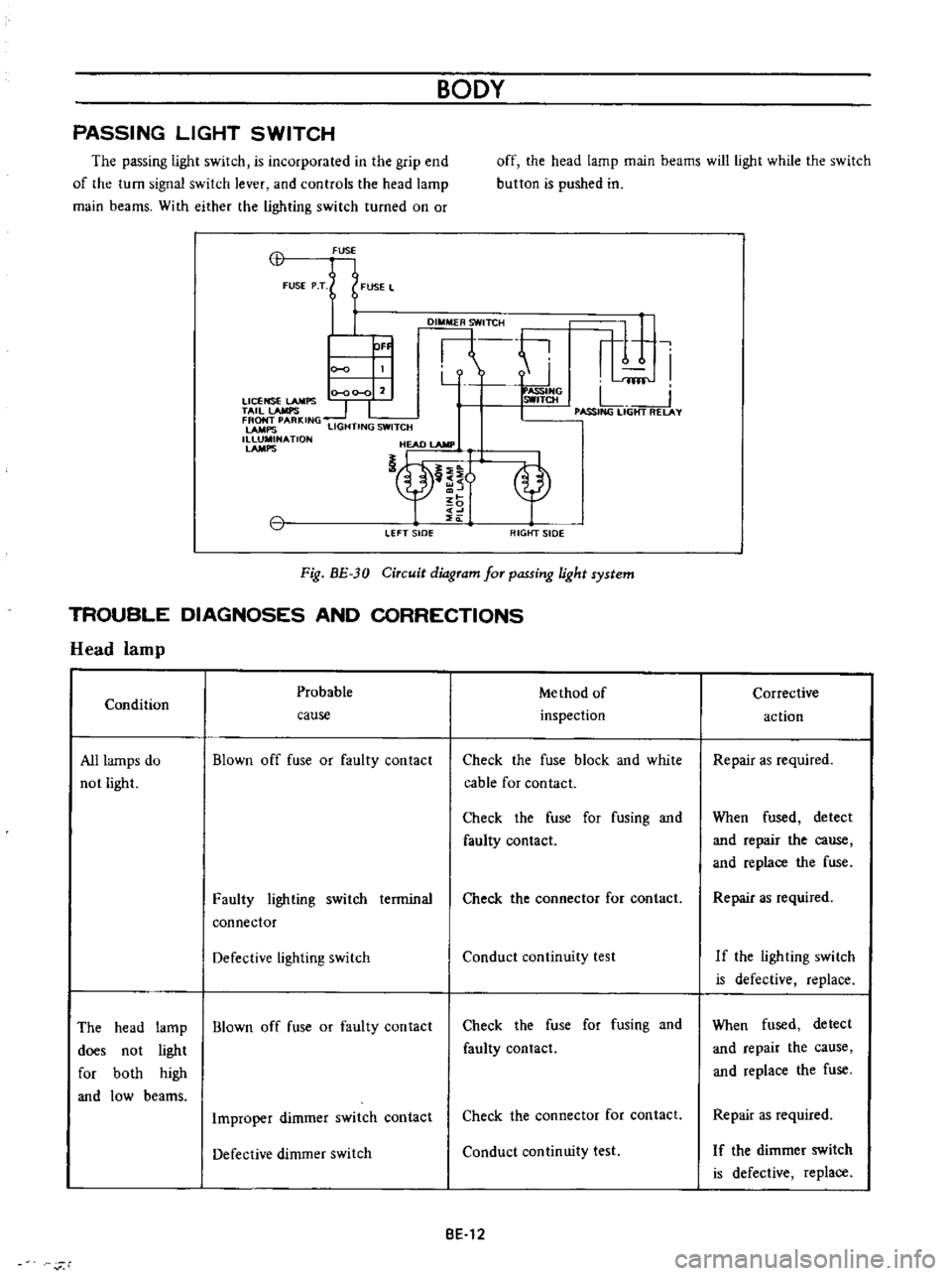
PASSING
LIGHT
SWITCH
The
passing
light
switch
is
incorporated
in
the
grip
end
of
the
turn
signal
switch
lever
and
controls
the
head
lamp
main
beams
With
either
the
lighting
switch
turned
on
or
off
the
head
lamp
main
beams
will
light
while
the
switch
button
is
pushed
in
CB
FUSE
FUSE
P
T
FUSE
L
DI
TCH
ti
r
1
I
Y
fflf
0
00
0
2
ASSIHG
LICENSE
LAMPS
SWITCH
L
TAil
lAMPS
1
I
I
PASSING
LIGHT
RELAY
FRONT
PARKING
LAMPS
LIGHTING
SWITCH
1
NATlON
HEAD
lAMP
nt
OF
LEFT
sIDe
RIGtfT
SIDE
Fig
BE
30
Circuit
diagram
for
passing
light
system
TROUBLE
DIAGNOSES
AND
CORRECTIONS
Head
lamp
Probable
Me
thod
of
Condition
inspection
cause
All
lamps
do
not
light
Blown
off
fuse
or
faulty
contact
Check
the
fuse
block
and
white
cable
for
contact
Check
the
fuse
for
fusing
and
faulty
contact
Faulty
lighting
switch
terminal
connector
Check
the
connector
for
contact
Defective
lighting
switch
Conduct
continuity
test
The
head
lamp
Blown
off
fuse
or
faulty
contact
does
not
light
for
both
high
and
low
beams
Check
the
fuse
for
fusing
and
faulty
contact
Improper
dimmer
switch
contact
Check
the
connector
for
contact
Defective
dimmer
switch
Conduct
continuity
test
BE
12
r
Corrective
action
Repair
as
required
When
fused
detect
and
repair
the
cause
and
replace
the
fuse
Repair
as
required
If
the
ligh
ting
swi
tch
is
defective
replace
When
fused
detect
and
repair
the
cause
and
replace
the
fuse
Repair
as
required
I
f
the
dimmer
switch
is
defective
replace
Page 251 of 513

9HORN
r
I
01
8ATTERY
HI
IGI
s
ILl
C
iORN
BODY
FUSE
H
S
HORN
BUTTON
BGI
J
H
B
S
Il
I
n6lm
I
L
J
L
HORN
RELAY
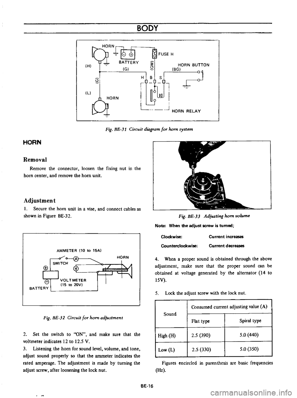
Fig
BE
3l
Circuit
diagram
for
hom
syrtem
HORN
Removal
Remove
the
connector
loosen
the
fixing
nut
in
the
horn
center
and
remove
the
horn
unit
Adjustment
1
Secure
the
horn
unit
in
a
vise
and
connect
cables
as
shown
in
Pigure
BE
32
AMMETER
110
to
15AI
Isw
f
@
113
I
VOLTMETER
I
15
to
20VI
BATTERY
HORN
Fig
BE
32
Circuit
for
ham
adjustment
2
Set
the
switch
to
ON
and
rnake
sure
that
the
voltmeter
indicates
12
to
12
5
V
3
Listening
the
horn
for
sound
level
volurne
and
tone
adjust
sound
properly
so
that
the
amrneter
indicates
the
rated
amperage
The
adjustment
is
made
by
turning
the
adjust
screw
after
loosening
the
lock
nut
Fig
BE
33
Adjusting
hom
IIOlume
Note
When
the
adjust
screw
is
turned
Clockwise
Counterclockwise
Current
increases
Current
decreases
4
When
a
proper
sound
is
obtained
through
the
above
adjustment
rnake
sure
that
the
proper
sound
can
be
obtained
at
voltage
generated
by
the
alternator
14
to
l5V
5
Lock
the
adjust
screw
with
the
lock
nut
Consumed
current
adjusting
value
A
Sound
Plat
type
Spiral
type
High
H
2
5
390
5
0
440
Low
L
2
5
330
5
0
350
Figures
encircled
in
parenthesis
are
basic
frequencies
Hz
BE
16