1968 DATSUN 510 radiator
[x] Cancel search: radiatorPage 94 of 252
COOLING
SYSTEM
89
FAN
CLUTCH
Fan
Clutch
Operation
and
Inspection
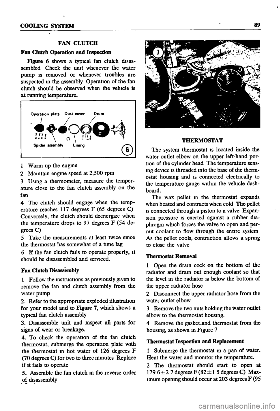
Figure
6
shows
a
typICal
fan
clutch
dISas
sembled
Check
the
umt
whenever
the
water
pump
IS
removed
or
whenever
troubles
are
suspected
m
the
assembly
OperatIon
of
the
fan
clutch
should
be
observed
when
the
vehIcle
is
at
nmning
temperature
Operation
plate
Dust
cover
Drum
o9
Q
SpIder
assembly
LIning
CD
1
Warm
up
the
engme
2
MaIntam
engIne
speed
at
2
500
rpm
3
Usmg
a
thermometer
measure
the
temper
ature
close
to
the
fan
clutch
assembly
on
the
fan
4
The
clutch
should
engage
when
the
temp
erature
reaches
17
degrees
F
65
degrees
C
Conversely
the
clutch
should
deenergIze
when
the
temperature
drops
to
97
degrees
F
54
de
grees
C
5
Take
the
measurements
at
least
twice
SInce
the
thermostat
has
somewhat
of
a
tlme
lag
6
If
the
fan
clutch
falls
to
operate
properly
It
should
be
dIsassembled
and
servIced
Fan
Clutch
Disassembly
1
Follow
the
mstructIons
as
prevIOusly
gIven
to
remove
the
fan
and
clutch
assembly
from
the
water
pump
2
Refer
to
the
appropnate
exploded
illustratIon
for
your
model
and
to
Figure
7
which
shows
a
typiCal
fan
clutch
assembly
3
DIsassemble
unit
and
mspect
all
parts
for
signs
of
wear
or
breakage
4
To
check
the
operatIon
of
the
fan
clutch
thermostat
submerge
the
operatIon
plate
With
the
thermostat
In
hot
water
of
126
degrees
F
70
degrees
C
for
two
to
three
mmutes
Replace
if
It
faIls
to
operate
5
Assemble
the
fan
clutch
m
the
reverse
order
o
dIsassembly
THERMOSTAT
The
system
thermostat
IS
located
inside
the
water
outlet
elbow
on
the
upper
left
hand
por
bon
of
the
cylInder
head
The
temperature
sens
Ing
deVice
IS
threaded
Into
the
base
of
the
therm
ostat
housmg
and
IS
connected
electrlcally
to
the
temperature
gauge
WIthIn
the
vehIcle
dash
board
The
wax
pellet
m
the
thermostat
expands
when
heated
and
contracts
when
cold
The
pellet
IS
connected
through
a
pIston
to
a
valve
Expan
sion
pressure
IS
exerted
agalUst
a
rubber
dIa
phragm
which
forces
the
valve
to
open
and
per
rrut
coolant
to
flow
through
the
entIre
system
As
the
pellet
cools
contractIOn
allows
a
spnng
to
close
the
valve
Thermostat
Removal
1
Open
the
draIn
cock
on
the
bottom
of
the
radiator
and
dram
out
enough
coolant
so
that
the
level
In
the
radIator
IS
below
the
bottom
of
the
upper
radIator
hose
2
DIsconnect
the
upper
radIator
hose
from
the
water
outlet
elbow
3
Remove
the
two
nuts
holdIng
the
water
outlet
elbow
to
the
thermostat
housmg
4
Remove
the
gasket
and
thermostat
from
the
housmg
as
shown
m
FIgure
7
Thermostat
Inspection
and
Replacement
Submerge
the
thermostat
In
a
pan
of
water
Heat
the
water
and
momtor
the
temperature
2
The
thermostat
should
start
to
open
at
1796
1
27
degrees
F
82
1
1
5
degrees
C
Max
Imum
opemng
should
occur
at
203
degrees
F
95
Page 95 of 252
90
CHAPTER
EIGHT
degrees
C
The
maXImum
WIdth
of
the
thermo
stat
openIng
should
be
0315
In
8mm
3
If
the
thermostat
IS
defectIve
or
If
you
have
an
doubts
about
It
mstall
a
new
one
4
When
Installmg
the
thermostat
m
the
hous
Ing
be
certaIn
to
place
the
spnng
end
down
Coat
both
SIdes
of
the
gasket
WIth
sealer
to
pre
vent
leaks
and
tIghten
the
mountlng
nuts
securely
RADIATOR
The
radIator
IS
of
conventional
desIgn
A
draIn
cock
IS
proVIded
at
the
bottom
back
to
perrmt
drainIng
The
system
IS
pressurized
and
the
rehef
valve
incorporated
In
the
filler
cap
mamtains
the
pressure
at
approximately
12
8
Ib
in
0
9
kg
cm
Coolant
capacity
is
1
691
gallons
6
4
lIters
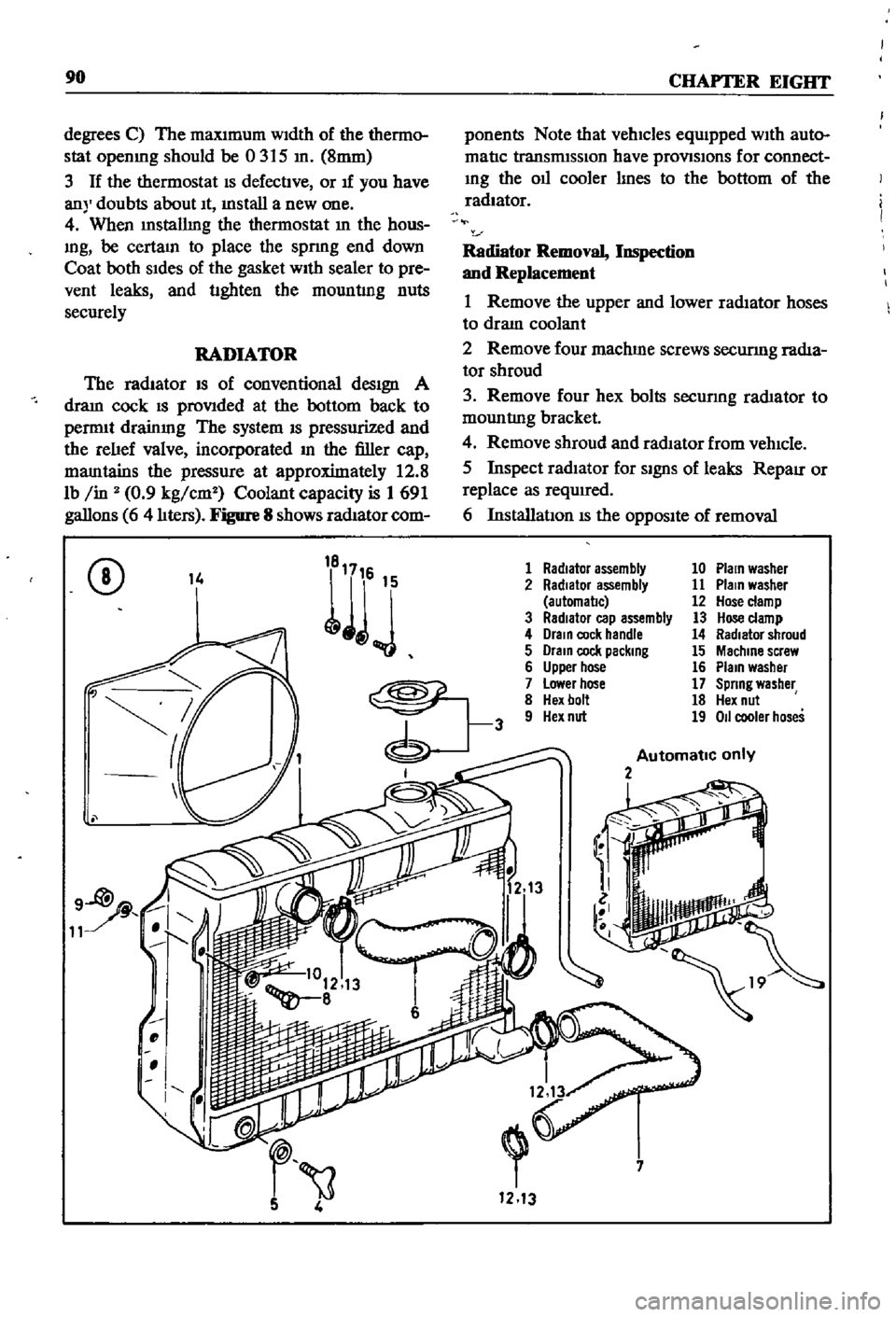
Figure
8
shows
radIator
com
ponents
Note
that
vehicles
equIpped
WIth
auto
matIc
transmISSIon
have
provlSlons
for
connect
Ing
the
011
cooler
lInes
to
the
bottom
of
the
radiator
Radiator
Removal
Inspection
and
Replacement
1
Remove
the
upper
and
lower
radIator
hoses
to
draIn
coolant
2
Remove
four
machme
screws
securmg
radIa
tor
shroud
3
Remove
four
hex
bolts
secunng
rad1ator
to
mountlng
bracket
4
Remove
shroud
and
radIator
from
vehIcle
5
Inspect
radIator
for
SignS
of
leaks
RepaIr
or
replace
as
required
6
InstallatIon
IS
the
OppOSIte
of
removal
CD
14
1
Radiator
assembly
10
Plain
washer
2
Radiator
assembly
11
Plain
washer
automal1c
12
Hose
clamp
3
RadIator
cap
assembly
13
Hose
clamp
4
Drain
cock
handle
14
Radiator
shroud
5
Drain
cock
packing
15
Machine
screw
6
Upper
hose
16
Plain
washer
7
Lower
hose
17
Spring
washer
8
Hex
bolt
18
Hex
nut
9
Hex
nut
19
011
cooler
hoses
Automatic
only
2
i
7
1213
Page 231 of 252
1
Radiator
grille
5
Screw
6
Washer
7
Washer
8
9
Head
lamp
finIsher
10
Screw
11
Nut
12
Hood
top
moulding
14
Screw
15
Washer
16
Moulding
19
Moulding
21
Front
apron
23
Front
bumper
24
Hex
bolt
with
washer
25
Washer
26
27
Bumper
stay
28
Bolt
29
Nut
30
Washer
31
Washer
32
Plug
34
35
Overrlder
36
Rubber
37
Washer
38
Lock
washer
39
Nut
40
41
Front
Fender
43
Hood
assembly
44
45
Hood
hinge
46
Bolt
47
Washer
48
49
Cowl
panel
50
Cowl
grille
51
Cowl
grille
cap
52
Sealing
rubber
52
1
14
V
27
r
l
DETAIL
A
23
8
41
t
l
Page 232 of 252
BODY
225
parts
as
requIred
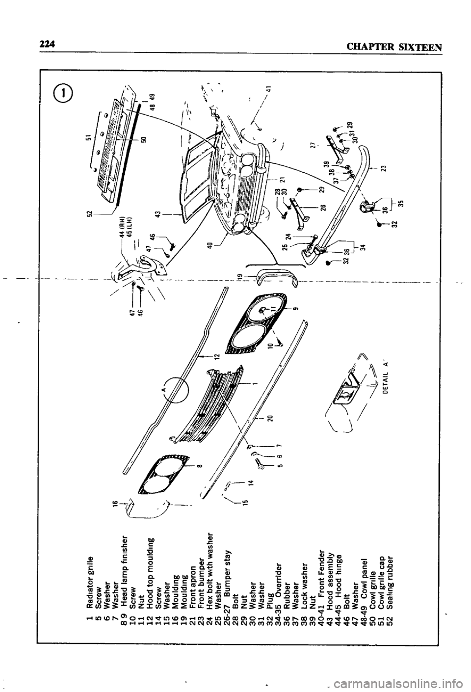
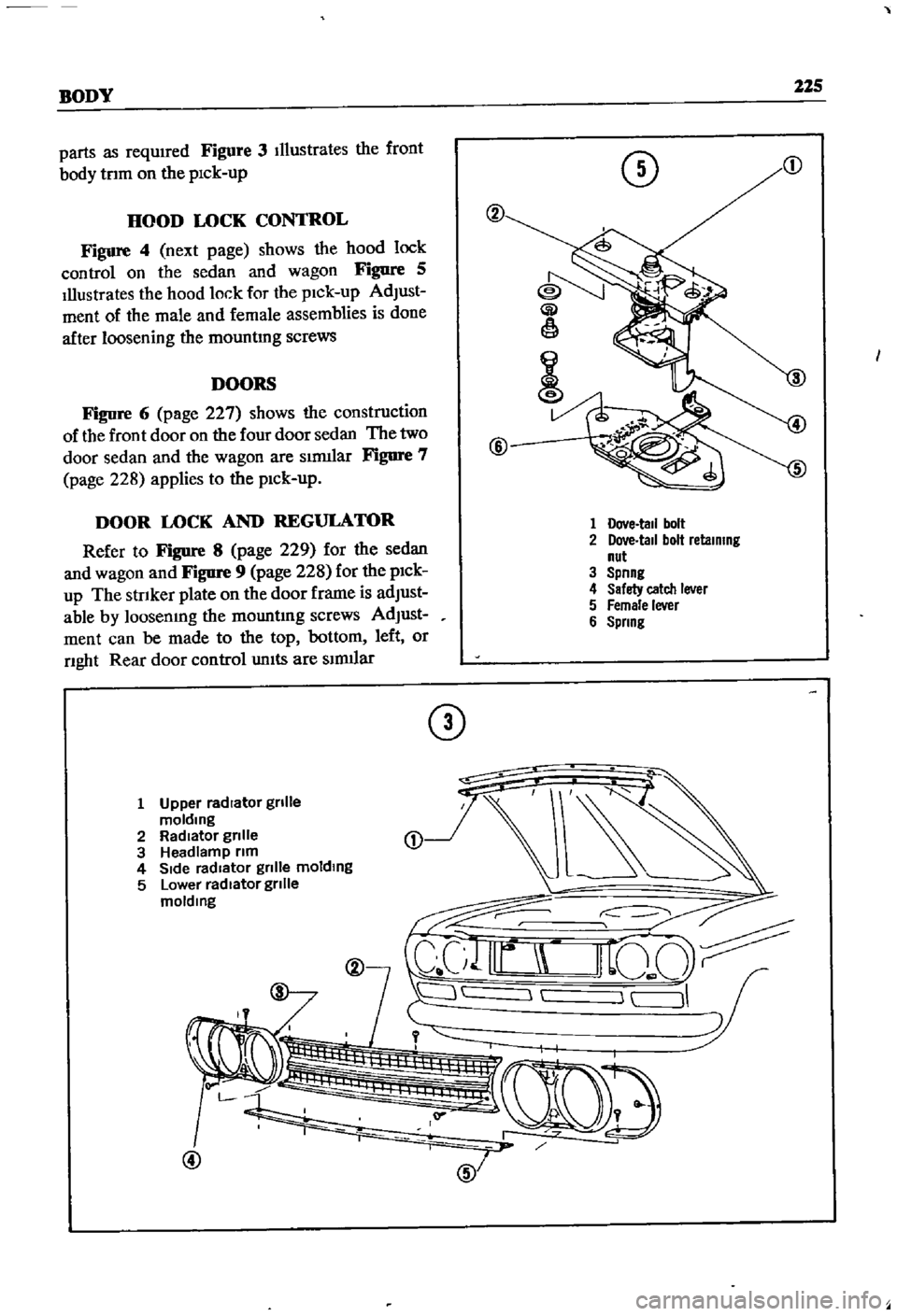
Figure
3
Illustrates
the
front
body
tnm
on
the
pick
up
DOORS
Figure
6
page
227
shows
the
construction
of
the
front
door
on
the
four
door
sedan
The
two
door
sedan
and
the
wagon
are
slrmlar
Figure
7
page
228
applies
to
the
pick
up
o
HOOD
LOCK
CONTROL
Figure
4
next
page
shows
the
hood
lock
control
on
the
sedan
and
wagon
Figure
5
Illustrates
the
hood
lock
for
the
pick
up
AdJust
ment
of
the
male
and
female
assemblies
is
done
after
loosening
the
mountmg
screws
Gi
1
@
DOOR
LOCK
AND
REGULATOR
Refer
to
Figure
8
page
229
for
the
sedan
and
wagon
and
Figure
9
page
228
for
the
pick
up
The
strIker
plate
on
the
door
frame
is
adJust
able
by
loosenmg
the
mOWltmg
screws
AdJust
ment
can
be
made
to
the
top
bottom
left
or
nght
Rear
door
control
units
are
slnuIar
1
Dove
tall
bolt
2
Dove
tall
bolt
retaining
nut
3
Spnng
4
Safety
catch
lever
5
Female
lever
6
Spring
CD
1
Upper
radIator
gnlle
molding
2
RadIator
gnlle
3
Headlamp
nm
4
SIde
radIator
gnlle
molding
5
Lower
radIator
gnlle
molding
L
@
Page 244 of 252
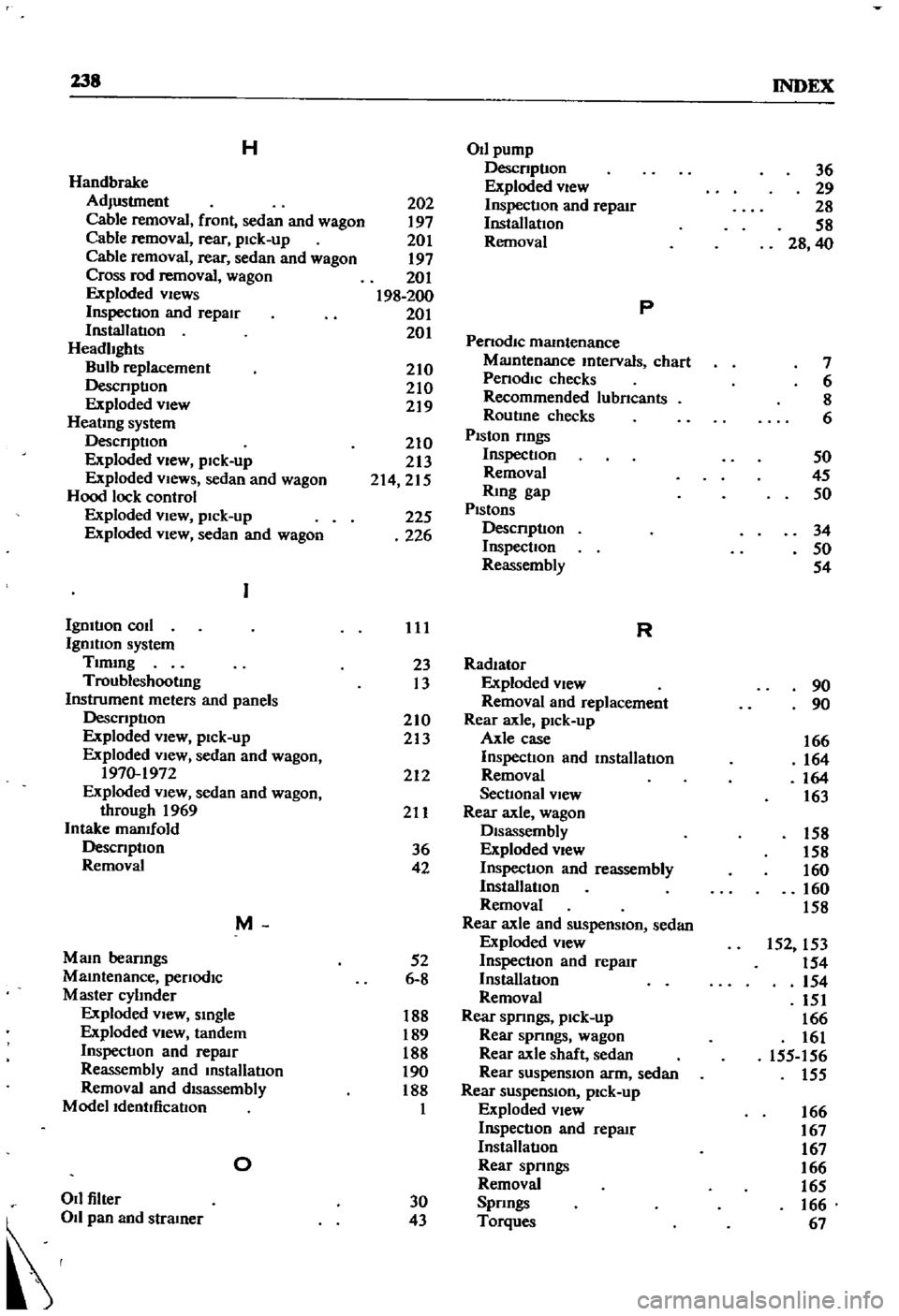
138
INDEX
H
OIl
pump
Descnptlon
36
Handbrake
Exploded
view
29
Adjustment
202
Inspection
and
repaIr
28
Cable
removal
front
sedan
and
wagon
197
Installation
58
Cable
removal
rear
pick
up
201
Removal
28
40
Cable
removal
rear
sedan
and
wagon
197
Cross
rod
removal
wagon
201
Exploded
views
198
200
p
Inspection
and
repair
201
Installation
201
Penodlc
mamtenance
Headlights
MaIntenance
mtervals
chart
7
Bulb
replacement
210
Penodlc
checks
6
Descnptlon
210
Recommended
lubncants
8
Exploded
view
219
Routine
checks
6
HeatIng
system
Piston
nngs
Descnptlon
210
Exploded
view
pick
up
213
Inspection
50
Exploded
VIews
sedan
and
wagon
214
215
Removal
45
Hood
lock
control
RIng
gap
50
Exploded
View
pick
up
225
Pistons
Descnptlon
34
Exploded
VIew
sedan
and
wagon
226
Inspection
50
Reassembly
54
Igmtlon
coil
111
R
Igmtlon
system
Tlmmg
23
Radiator
Troubleshooting
13
Exploded
view
90
Instrument
meters
and
panels
Removal
and
replacement
90
Descnptlon
210
Rear
axle
pick
up
Exploded
View
pick
up
213
Axle
case
166
Exploded
view
sedan
and
wagon
Inspection
and
mstalIatlon
164
1970
1972
212
Removal
164
Exploded
view
sedan
and
wagon
Sectional
view
163
through
1969
211
Rear
axle
wagon
Intake
manifold
Disassembly
158
Descnptlon
36
Exploded
view
158
Removal
42
Inspection
and
reassembly
160
InstallatIOn
160
Removal
158
M
Rear
axle
and
suspenSion
sedan
Exploded
view
152
153
Mam
beanngs
52
Inspection
and
repaIr
154
MaIntenance
penodlc
6
8
InstalIatlon
154
Master
cylInder
Removal
151
Exploded
vIew
smgle
188
Rear
spnngs
pick
up
166
Exploded
view
tandem
189
Rear
spnngs
wagon
161
Inspection
and
repllIr
188
Rear
axle
shaft
sedan
155
156
Reassembly
and
InstalIatlon
190
Rear
suspension
arm
sedan
155
Removal
and
disassembly
188
Rear
suspenSion
pick
up
Modelldentdicatlon
1
Exploded
view
166
Inspection
and
repllIr
167
InstalIatlon
167
0
Rear
spnngs
166
Removal
165
011
filler
30
Spnngs
166
d
43
Torques
67