1900 MITSUBISHI DIAMANTE oil filter
[x] Cancel search: oil filterPage 96 of 408
ENGINEANDENGINEOVERHAUL 3-35
Operating the engine without the proper
amount and type of engine oil will result in
severe engine damage.
33. Connect the negative battery cable and start
the engine.
34. Verify correct oil pressure
35. Inspect for leaks.
3.OL Engines
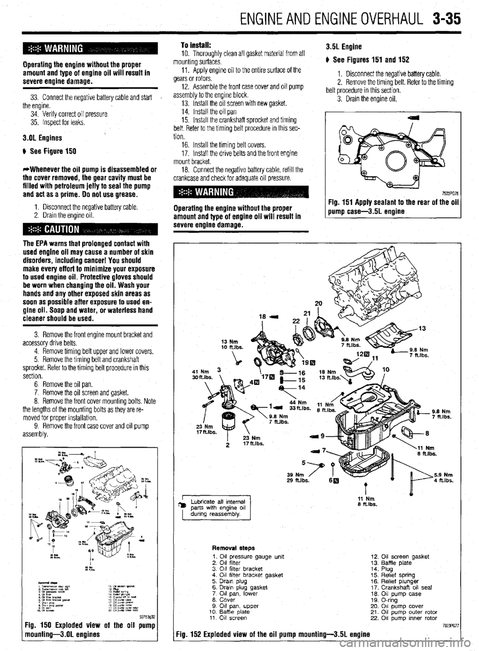
b See Figure 150
*Whenever the oil pump is disassembled or
the cover removed, the gear cavity must be
filled with petroleum jelly to seal the pump
and act as a prime. 00 not use grease.
1. Disconnect the negative battery cable.
2. Drain the engine oil.
The EPA warns that prolonged contact with
used engine oil may cause a number of skin
disorders, including cancer! You should
make every effort to minimize your exposure
to used engine oil. Protective gloves should
be worn when changing the oil. Wash your
hands and any other exposed skin areas as
soon as possible after exposure to used en-
gine oil. Soap and water, or waterless hand
cleaner should be used.
3. Remove the front engine mount bracket and
accessory drive belts.
4. Remove timing belt upper and lower covers.
5. Remove the timing belt and crankshaft
sprocket. Refer to the timing belt procedure in this
section.
6 Remove the oil pan.
7. Remove the oil screen and gasket.
8. Remove the front cover mounting bolts. Note
the lengths of the mounting bolts as they are re-
moved for proper installation.
9. Remove the front
assembly. and oil pump
9315393i 7g. 150 Exploded view of the oil pump
nounting-3.01 engines
To install:
10. Thoroughly clean all gasket material from all
mounting surfaces.
11. Apply engine oil to the entire surface of the
gears or rotors.
12. Assemble the front case cover and oil pump
assembly to the engine block.
13. Install the oil screen with new gasket.
14. Install the oil pan
15. Install the crankshaft sprocket and timing
belt. Refer to the timing belt procedure in this sec-
tion 3.5L Engine
p See Figures 151 and 152
1. Disconnect the negative battery cable.
2. Remove the timing belt. Refer to the timing
belt procedure in this section.
3. Drain the engine oil.
16. Install the timing belt covers.
17. Install the drive belts and the front engine
mount bracket.
18. Connect the negative battery cable, refill the
crankcase and check for adequate oil pressure.
Operating the engine without the proper
amount and type of engine oil will result in
severe engine damage. Fig. 151 Apply sealant to the rear of the oil
pump case-3.5L ermine
I 11 Nm
8 ft.lbs.
Removal steps
7g. 152 Exploded view of the oil pump mounting-3.51 engine
1. 011 pressure gauge unit
2. 011 filter
3. 011 filter bracket
4. 011 filter bracket gasket
5. Drain plug
6. Drawn plug gasket
7 011 lower pan,
8. Cover
9 011 pan, upper
10. Baffle date 11. 011 screen
12.
13.
14.
15.
16.
17.
10.
19.
20.
21.
22. Oil screen gasket
Baffle plate
Plug
Reltef spring
Relief plunger
Crankshaft oil seal
Oil pump case
0-ring
011 pump cover
011 pump outer rotor
011 pump inner rotor
Page 97 of 408
3-36 ENGINEANDENGINEOVERHAUL
The EPA warns that urolonaed contact with
used engine oil may cause”a number of skin
disorders, including cancer! You should
make every effort to minimize your exposure
to
used engine oil. Protective gloves should
be worn when changing the oil. Wash your
hands and any other exposed skin areas as
soon as possible after exposure to
used en-
gine oil. Soap and water, or waterless hand
cleaner should be used.
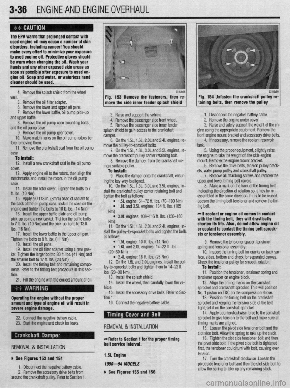
4. Remove the solash shield from the wheel
93153p65 93153p60 well.
5. Remove the oil filter adapter.
6. Remove the lower and upper oil pans.
7. Remove the lower baffle, oil pump pick-up
and upper baffle.
8. Remove the oil pump case mounting bolts
and the oil pump case.
9. Remove the oil pump gear cover.
10. Make matchmarks on the oil pump rotors be-
fore removing them.
,,. r.-- -IL- -.( -L.11---‘I --. IL- -.I _ --
nemove me cranksnarr sear rrom me 011 pump
case.
To instell:
12. Install a new crankshaft seal in the oil pump
cover.
13. Apply engine oil to the rotors, then align the
matchmarks and install the rotors in the oil pump Fig. 153 Remove the fasteners, then re-
move the side inner fender splash shield
3. Raise and support the vehicle.
4. Remove the passenger side front wheel.
5. Remove the passenger side inner fender
splash shield to gain access to the crankshaft
damper.
6. On the 1.5L, 1.6L, 2.OL and 2.4L engines, re-
move the oullev-to-sorocket bolts.
7. On thei .5L, i .8L, 3.OL and 3.5L engines, re-
move the crankshaft pulley center retaining bolt.
8. Remove the damper from the crankshaft us
ing a suitable puller.
-la install:
9. Place the damper onto the crankshaft, ensur-
ing the key-way is aligned.
10. On the 1.5L, 1.8L, 3.OL and 3.5L engines, in-
e crankshaft pulley center retaining bolt and
the bolt as follows: Fig. 154 Unfasten the crankshaft pulley re-
talning bolts, then remove the pulley
case.
14. Install the rotor cover. Tighten the bolts to 7
ft. Ibs. (10 Nm).
15. Apply a 0.113 in. (3mm) bead of sealant to
the back of the oil pump case. I[ -‘-‘I IL -~-- IL-
nsrall me ca
se on me engine and tighten the bolts to IOft Ihc 11 ,,, -. , .4 Nm).
16. Install the upper baffle r tlal te and oil pump
pick-up using a new gasket. Tic fhtti,, ,,lG va,,,ti ““a,., an tha hafflc, hnltc to 7 ft. Ibs. (10 Nm) and the pit k-up bolts to 13 ft.
Ibs. (18 Nm).
17. Install the lower baffle in the upper oil pan.
Tighten the bolts to 8 ft. Ibs. (11 Nm).
18. Install the oil pans.
19. Install the oil filter adapter using a new gas-
ket. Tighten the larger bolt to 30 ft. Ibs. (41 Nm) and
the smaller bolt to 1’ u ‘L- Inn ‘I--’ stall thl
tighten
4
) 1.5L engine: 51-72 ft. Ibs. (70-100 Nm)
l 1.8L and 3.5L engines: 134 ft. Ibs. (185
NM
l 3.OL engines: 108-116 ft. lbs. (150-160 NW 11. On the 1.5L, 1.6L, 2.OL and 2.4L engines, in-
stall the pulley-to-sprocket bolts and tighten the bolts
as follows:
l 1.5L engine: 10 ft. Ibs. (14 Nm)
* 1.6L and 2.OL engines: 14-22 ft. Ibs. 1. Disconnect the negative battery cable.
2. Remove the engine under cover.
3. Raise and safely support the weight of the en-
gine using the appropriate equipment. Remove the
front engine mount bracket and accessory drive belts.
4. If necessary, remove the coolant reservoir
tank.
5. Using the proper equipment, slightly raise
ets, water pump pulley
7. Remove all attr
upper and lower timin{
8. Make a mark o
indicating the directior
assembled in the same the engine to take the weight off the side engine
mount. Remove the engine mount bracket.
6. Remove the drive belts, tension pulley brack-
and crankshaft pulley.
aching screws and remove the
J belt covers.
n the back of the timing belt
I of rotation so it may be re-
! direction if it is to be reused.
tensioner and remove the tim-
Loosen the timing belt
ing belt.
*If coolant or engine oil comes in contact
with the timing bplt thaw will r(mcti~~llv Wll L, .,,s,, n,,, u,uu.,vu,,,
shorten its life. A ,IS o, do not allow engine oil
#.I nn..lr”* In rind In,
“I IruuI(IIIL Lu Irulll&t the timing belt sprock-
ets or tensioner assembly.
9. Remove the tensioner spacer, tensioner
spring and tensioner assembly.
cracks on back sur-
;eoarated canvas.
20. Install the tilllIllY uljllOllu IclllallllllY ~ullIPV-
:
nents. Refer to the timing belt procedure in this sec-
: tion.
21. Fill the engine with the correct amount of oil.
I . (20-30 Nm)
l 2.4L engine: 18 ft. Ibs. (25 Nm)
12. On the 1.6L and 2.OL engines, install the pul-
ley-to-sprocket bolts and tighten them to 14-22 ft.
Ibs. (20-30 Nm).
13. Install the splash shield.
14. Install the wheel, then carefully lower the ve- 10. Inspect the timing belt for I
face, sides, bottom and check for ! (
Check the tensioner pulley for smooth rotation.
To install:
11. Position the tensioner, tensioner spring and
tensioner spacer on engine block.
12. Align the timing marks on the camshaft
ft sprocket. This will position
tn the comoression stroke.
I hicle.
sprocket and cranksha
15. Install the accessory drive belts. Refer to Sec-
No. 1 piston on TDC o
Operating the engine without the proper tion 1.
13. Position the timing belt on the crankshaft
amount and type of engine oil will result in 16. Connect the negative battery cable.
sprocket and keeping the tension side of the bolt
severe engine damage.
-
22. -s
Chrmxt the nenntive h;lttm cnhle --, , I” ,.-J XL.._ I -..-., --I.-.
23. Start the engine and check for leaks.
REMOVAL &INSTALLATION
tight, set it on the cam, shaft sprocket.
14. Apply counterc Yockwise force to the camshaft
snrnckd tn nive tensin In -r .__.._. ._ J..- ._ - _ to the belt and make sure all
timing marks are aligned.
15. Loosen the pivot side tensioner bolt and the
clnt
&In hnlt Allnur thn rnrinn tn tdm III-I thn slack, cl then , d I, I’ r),“I 44”” ““IL. “ll”sl LllU .y”“yj L” L”I\U Low Ul” L .-Refer to Section 1 for the proper timing 16. Tighten the slot side tensioner bolt ark
., , , , ,, ,, ,, , , , , ,, . ,, ,~
REMOVAL &INSTALLATION
6 See Figures 153 and 154
1. Disconnect the negative battery cable.
2. Remove the accessory drive belts from
around the crankshaft pulley. Refer to Section 1. belt service interval.
1.5L Engine
1999-94 MODELS
b See Figures 155 and 156 me p~vor sloe DOI~. IT me p~vor sloe OOII
IS ogntened
first, the tensioner could turn with bolt, causing over
tension.
17. Turn the crankshaft clockwise. Loosen the
pivot side tensioner bolt and then the slot side bolt to
allow the spring to take up any remaining slack.
Page 115 of 408
3-54 ENGINEANDENGINEOVERHALJL
from the, access may be possible (though a little
awkward) to measure the camshaft lobes using a mi-
crometer
In any case, two measurements are necessary for
each lobe. Measurement Y or the total LOBE HEIGHT
and measurement X or the total LOBE WIDTH. To
find the lobe lift, you simply subtract X from Y (sub-
tract the width from the height).
Note each measurement, then make your calcula-
tion to determine the lift. Note the final results and re-
peat the process on the remaining camshaft lobes.
Finally, you should compare your results to the spec-
ifications charts and decide if a new camshaft is in
your future.
REMOVAL &INSTALLATION
2.OL and 2.4L Engines
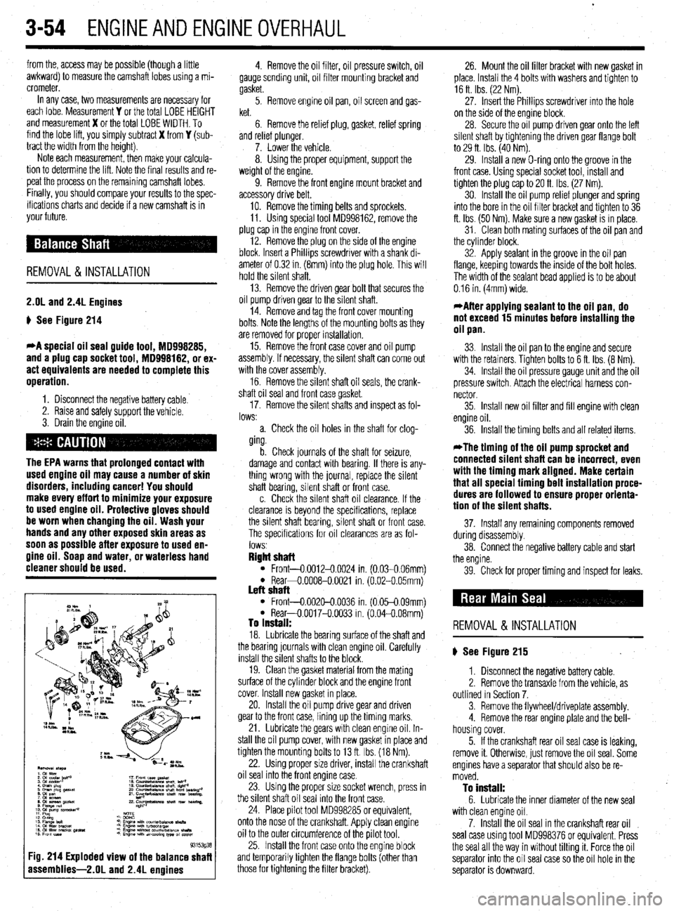
p See Figure 214
*A special oil seal guide tool, 18998285,
and a plug cap socket tool, MD998182, or ex-
act equivalents are needed to complete this
operation.
1. Disconnect the negative battery cable.
2. Raise and safely support the vehicle.
3. Drain the engine oil.
The EPA warns that prolonged contact with
used engine oil may cause a number of skin
disorders, including cancer! You should
make every effort to minimize your exposure
to used engine oil. Protective gloves should
be worn when changing the oil. Wash your
hands and any other exposed skin areas as
soon as possible after exposure to used en-
gine oil. Soap and water, or waterless hand
cleaner should be used.
93153g3
:ig. 214 Exploded view of the balance shaf
assemblies-2.01 and 2.4L enoines
4. Remove the oil filter, oil pressure switch, oil
gauge sending unit, oil filter mounting bracket and
gasket.
5. Remove engine oil pan, oil screen and gas-
ket.
6. Remove the relief plug, gasket, relief spring
and relref plunger.
7. Lower the vehicle.
8. Using the proper equipment, support the
weight of the engine.
9. Remove the front engine mount bracket and
accessory drive belt,
10. Remove the timing belts and sprockets.
11. Using special tool MD998162, remove the
plug cap in the engine front cover.
12. Remove the plug on the side of the engine
block. Insert a Phillips screwdriver with a shank di-
ameter of 0.32 in. (8mm) into the plug hole. This will
hold the silent shaft.
13. Remove the driven gear bolt that secures the
oil pump driven gear to the silent shaft.
14. Remove and tag the front cover mounting
bolts. Note the lengths of the mounting bolts as they
are removed for proper installation.
15. Remove the front case cover and oil pump
assembly. If necessary, the silent shaft can come out
with the cover assembly.
16. Remove the silent shaft oil seals, the crank-
shaft oil seal and front case gasket
17. Remove the silent shafts and inspect as fol-
lows:
a. Check the oil holes in the shaft for clog-
ging.
b. Check journals of the shaft for seizure,
damage and contact with bearing. If there is any-
thing wrong with the journal, replace the silent
shaft bearing, silent shaft or front case.
c. Check the silent shaft oil clearance. If the
clearance is beyond the specifications, replace
the silent shaft bearing, silent shaft or front case.
The specifications for oil clearances are as fol-
lows
Right shaft l Front-0.0012-0.0024 in. (0.030.06mml l Rear+0.0008-0.0021 in. (6.02-O 05mm) Left shaft l Front-0.002&0.0036 in. (0.05-0.09mm) l Rear-O.0017-O.0033 in. (0.04-0.08mm) To install: 18. Lubricate the bearing surface of the shaft and
the bearing journals with clean engine oil. Carefully
install the silent shafts to the block.
19. Clean the gasket material from the mating
surface of the cylinder block and the engine front
cover. Install new gasket in place.
20. Install the oil pump drive gear and driven
gear to the front case, lining up the timing marks.
21. Lubricate the gears with clean engine oil. In-
stall the oil pump cover, with new gasket in place and
tighten the mounting bolts to 13 ft. Ibs. (18 Nm).
22. Using proper size driver, install the crankshaft
oil seal into the front engine case.
23. Using the proper size socket wrench, press in
the silent shaft oil seal into the front case.
24. Place pilot tool MD998285 or equivalent,
onto the nose of the crankshaft. Apply clean engine
oil to the outer circumference of the pilot tool.
25. Install the front case onto the engine block
and temporarily tighten the flange bolts (other than
those for tightening the filter bracket). 26. Mount the oil filter bracket with new gasket in
place. Install the 4 bolts with washers and tighten to
16 ft Ibs. (22 Nm).
27. Insert the Phillips screwdriver into the hole
on the side of the engine block.
28. Secure the oil pump driven gear onto the left
silent shaft by tightening the driven gear flange bolt
to 29 ft. Ibs. (40 Nm).
29. Install a new O-ring onto the groove in the
front case. Using special socket tool, install and
tighten the plug cap to 20 ft. Ibs (27 Nm).
30. Install the oil pump relief plunger and spring
into the bore in the oil filter bracket and tighten to 36
ft. Ibs. (50 Nm). Make sure a new gasket is in place.
31. Clean both mating surfaces of the oil pan and
the cylinder block.
32. Apply sealant in the groove in the oil pan
flange, keeping towards the inside of the bolt holes.
The width of the sealant bead applied is to be about
0.16 in. (4mm) wide.
*After applying sealant to the oil pan, do
not exceed 15 minutes before installing the
oil pan.
33. Install the oil pan to the engine and secure
with the retainers. Tighten bolts to 6 ft. Ibs. (8 Nm).
34. Install the oil pressure gauge unit and the oil
pressure switch. Attach the electrical harness con-
nector
35. Install new oil filter and fill engine with clean
engine oil.
36. Install the timing belts and all related items,
*The timing of the oil pump sprocket and
connected silent shaft can be incorrect, even
with the timing mark aligned. Make certain
that all special timing belt installation proce-
dures are followed to ensure proper orienta-
tion of the silent shafts.
37. Install any remaining components removed
during disassembly.
38. Connect the negative battery cable and start
the engine.
39. Check for proper timing and inspect for leaks.
REMOVAL &INSTALLATION
p See Figure 215
1. Disconnect the negative battery cable.
2. Remove the transaxle from the vehicle, as
outlined in Section 7.
3. Remove the flywheel/driveplate assembly.
4. Remove the rear engine plate and the bell-
housing cover.
5. If the crankshaft rear oil seal case is leaking,
remove it. Otherwise, just remove the oil seal. Some
engines have a separator that should also be re-
moved.
To install: 6. Lubricate the inner diameter of the new seal
with clean engine oil.
7. Install the oil seal in the crankshaft rear oil
seal case using tool MD998376 or equivalent. Press
the seal all the way in without tilting it. Force the oil
separator into the oil seal case so the oil hole in the
separator is downward.
Page 118 of 408
ENGINEANDENGINEOVERHAUL 3-57
Anything that generates heat and/or friction WIII
eventually burn or wear out (for example, a light bulb
generates heat, therefore its life span is limited). With
this in mind, a running engine generates tremendous
amounts of both; friction is encountered by the mov-
ing and rotating parts inside the engine and heat is
created by friction and combustion of the fuel How-
ever, the engine has systems designed to help reduce
the effects of heat and friction and provide added
longevrty. The oiling system reduces the amount of
friction encountered by the moving parts inside the
engine, while the cooling system reduces heat cre-
ated by friction and combustion If either system is
not maintained, a break-down will be inevitable.
Therefore, you can see how regular maintenance can
affect the service life of your vehicle, If you do not
drain, flush and refill your cooling system at the
proper intervals, deposits WIII begin to accumulate in
the radiator, thereby reducing the amount of heat it
can extract from the coolant The same applies to
your oil and filter; If it is not changed often enough it
becomes laden with contaminates and is unable to
properly lubricate the engine. This increases friction
and wear.
There are a number of methods for evaluating the
condition of your engine. A compression test can re-
veal the condition of your pistons, piston rings,
cylinder bores, head gasket(s), valves and valve
seats. An oil pressure test can warn you of possible
engine bearing, or oil pump failures. Excessrve oil
consumption, evidence of oil in the engine air intake
area and/or bluish smoke from the tailpipe may indi-
cate worn piston rings, worn valve guides and/or
valve seals. As a general rule, an engine that uses no
more than one quart of oil every 1000 miles is in
good condition. Engines that use one quart of oil or
more in less than 1000 miles should first be checked
for oil leaks. If any oil leaks are present, have them
fixed before determining how much oil is consumed
by the engine, especrally if blue smoke is not visible
at the tailpipe
COMPRESSION TEST
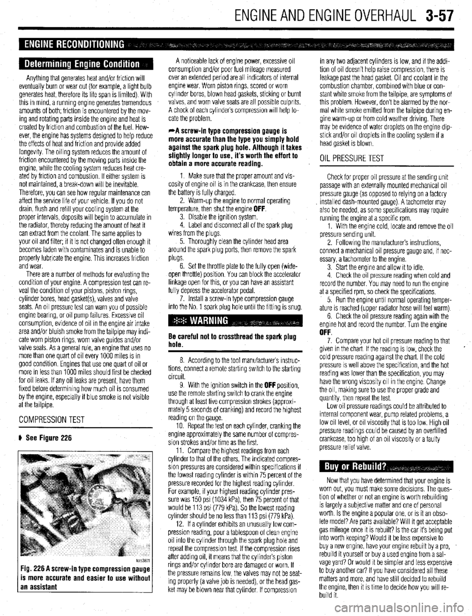
# See Figure 226
tccs3801 Fig. 226 A screw-in type compression gauge
is more accurate and easier to use without
an assistant
A noticeable lack of engine power, excessive oil
consumption and/or poor fuel mileage measured
over an extended period are all indicators of internal
engine wear. Worn piston rings, scored or worn
cylinder bores, blown head gaskets, sticking or burnt
valves, and worn valve seats are all possible culprits.
A check of each cylinders compression WIII help lo-
cate the problem.
*A screw-in type compression gauge is
more accurate than the type you simply hold
against the spark plug hole. Although it takes
slightly longer to use, it’s worth the effort to
obtain a more accurate reading.
1 Make sure that the proper amount and vis-
cosity of engine oil is in the crankcase, then ensure
the battery is fully charged.
2. Warm-up the engine to normal operating
temperature, then shut the engine
OFF. 3. Disable the ignition system.
4. Label and disconnect all of the spark plug
wires from the plugs,
5. Thoroughly clean the cylinder head area
around the spark plug ports, then remove the spark
plugs.
6. Set the throttle plate to the fully open (wide-
open throttle) position You can block the accelerator
linkage open for this, or you can have an assistant
fully depress the accelerator pedal.
7. Install a screw-in type compression gauge
into the No. 1 spark plug hole until the fitting is snug.
Be careful not to crossthread the spark plug
hole.
8. According to the tool manufacturers instruc-
tions, connect a remote starting switch to the starting
circuit.
9. With the ignition switch in the
OFF position,
use the remote starting switch to crank the engine
through at least five compression strokes (approxi-
mately 5 seconds of cranking) and record the highest
reading on the gauge
10. Repeat the test on each cylinder, cranking the
engine approximately the same number of compres-
sion strokes and/or time as the first.
11. Compare the hrghest readings from each
cylinder to that of the others. The indicated compres-
sion pressures are considered within specifications if
the lowest reading cylinder is within 75 percent of the
pressure recorded for the highest reading cylinder
For example, if your highest reading cylinder pres-
sure was 150 psi (1034 kPa), then 75 percent of that
would be 113 psi (779 kPa). So the lowest reading
cylinder should be no less than 113 psi (779 kPa).
12. If a cylinder exhibits an unusually low com-
pression reading, pour a tablespoon of clean engine
oil into the cylinder through the spark plug hole and
repeat the compression test. If the compression rises
after adding oil, it means that the cylinder’s piston
rings and/or cylinder bore are damaged or worn, If
the pressure remains low, the valves may not be seat-
ing properly (a valve job is needed), or the head gas-
ket may be blown near that cylinder. If compression in any two adjacent cylinders is low, and if the addi-
tion of oil doesn’t help raise compression, there is
leakage past the head gasket. Oil and coolant in the
combustion chamber, combined with blue or con-
stant white smoke from the tailpipe, are symptoms of
this problem. However, don’t be alarmed by the nor-
mal white smoke emitted from the tailpipe during en-
gine warm-up or from cold weather driving. There
may be evidence of water droplets on the engine dip-
stick and/or oil droplets in the cooling system if a
head gasket is blown.
OIL PRESSURETEST
Check for proper oil pressure at the sending unit
passage with an externally mounted mechanical oil
pressure gauge (as opposed to relying on a factory
Installed dash-mounted gauge). A tachometer may
also be needed, as some specifications may require
running the engine at a specific rpm.
1. With the engine cold, locate and remove the oil
pressure sending unit.
2. Followrng the manufacturers instructions,
connect a mechanical oil pressure gauge and, if nec-
essary, a tachometer to the engine.
3 Start the engine and allow it to idle.
4 Check the oil pressure reading when cold and
record the number. You may need to run the engine
at a specified rpm, so check the specifications,
5. Run the engine until normal operating temper-
ature is reached (upper radiator hose will feel warm)
6. Check the oil pressure reading again with the
engine hot and record the number. Turn the engine
OFF. 7. Compare your hot oil pressure reading to that
given in the chart If the reading is low, check the
cold pressure reading against the chart. If the cold
pressure IS well above the specification, and the hot
reading was lower than the specification, you may
have the wrong viscosity oil in the engine. Change
the oil, making sure to use the proper grade and
quantity, then repeat the test.
Low oil pressure readings could be attributed to
internal component wear, pump related problems, a
low oil level, or oil viscosity that is too low. High oil
pressure readings could be caused by an overfilled
crankcase, too htgh of an oil viscosity or a faulty
pressure relief valve.
Now that you have determined that your engine is
worn out, you must make some decisions. The ques-
tion of whether or not an engine IS worth rebuilding
is largely a subjective matter and one of personal
worth. Is the engine a popular one, or IS it an obso-
lete model? Are parts available? Will it get acceptable
gas mileage once It is rebuilt? Is the car its being put
into worth keeping? Would it be less expensive to
buy a new engine, have your engine rebuilt by a pro,
rebuild it yourself or buy a used engine from a sal-
vage yard? Or would It be simpler and less expensive
to buy another car? If you have considered all these
matters and more, and have still decided to rebuild
the engine, then it is time to decide how you will re-
build it.
Page 130 of 408
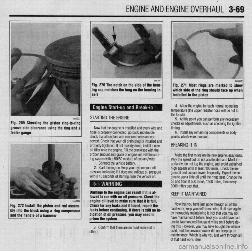
ENGINEANDENGINEOVERHAUL 3-69
STARTING THE ENGINE
clearance using the ring and a Now that the engine is installed and every wire and
hose is properly connected, go back and double
check that all coolant and vacuum hoses are con-
, netted. Check that your oil drain plug is installed and
tt tl
C ti
hYs3222 Fig. 271 Most rings are marked to show
which side of the ring should face up when
installed to the piston
J
4. Allow the engine to reach normal operating
?mperature (the upper radiator hose will be hot to
ie touch).
5. At this point you can perform any necessary
hecks or adjustments, such as checking the ignition
ming.
6. Install any remaining components or body
anels which were removed.
IREAKING IT IN
Make the first miles on the new engine, easy ones.
arv the soeed but do not accelerate hard. Most im-
oriantly, do not lug the engine, and avoid sustained
igh speeds until at least 100 miles. Check the en-
ine oil and coolant levels frequently. Expect the en-
ine to use a little oil until the rings seat. Change the
il and filter at 500 miles, 1500 miles, then every
Page 143 of 408
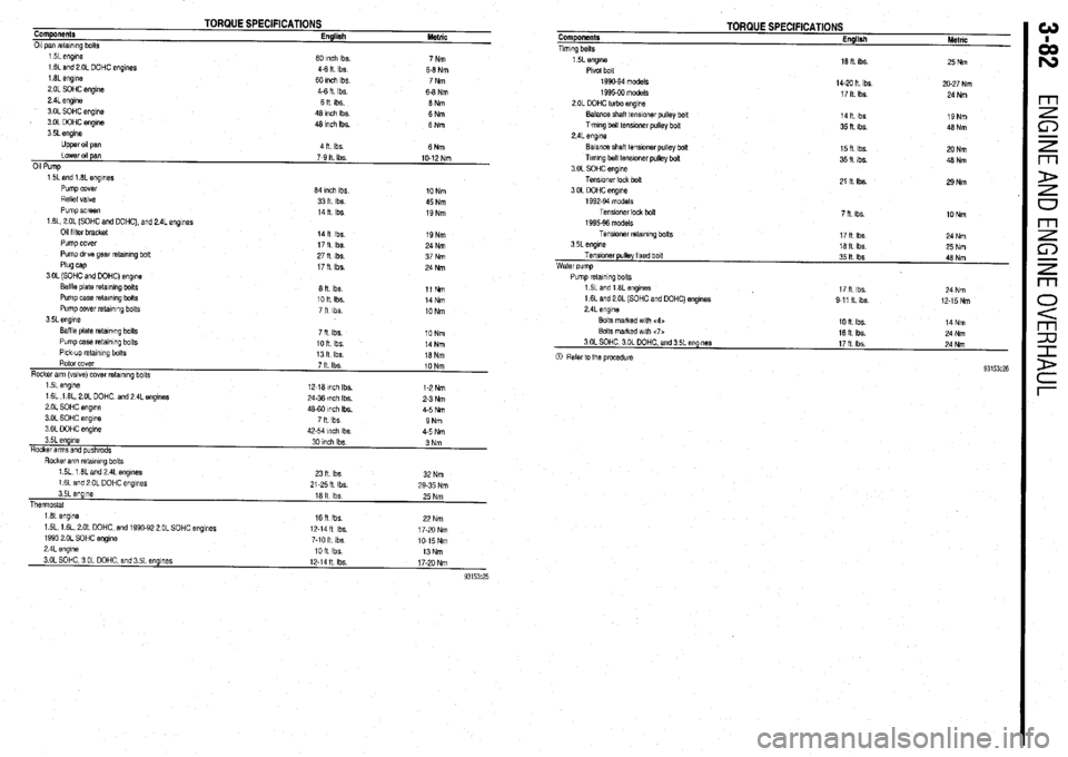
TORQUE SPECIFICATIONS Components TORQUE SPECIFICATIONS
011 pan retamg bolls
15L eng,ne
1 6L and 2 OL LXJHC
engmes
1 EL
eqne
2 OL SOHC engme
2 4L
eng,ne
3 OL SOHC engme
3 OL DOHC engme
3 5L engme
Upper 011 pan
Lower 011 pa”
011 Pump
1 5L and 16L engmes
Pump cover
RM valve
Pump screen
16L, 2 OL (SOHC and DOHC), and 2 4L engmes
011 filter bracket
Pump wver
Pump drive gear retammg bolt
Plug cap
3 OL (SOHC and DOHC) engme
Ballle plate retalnlng bolts
Pump case retammg bolts
Pump cover retamng bolts
3 5L engme
Baffle plate retammg bolts
Pump case retalmng bolts
Pick-up retalnmg bolts
Rotor cover
Rocker arm (valve) cover retalnmg bolts
1 5L
engine
1 6L ,l EL, 2 OL DOHC. and 2 4L
engines
2 OL SOHC
engme
3 OL SOHC engine
3 OL DOHC
engme
3.5L eng,ne
Rocker arms and pushrods
Rocker arm retalmng bolts
15L, 1 6L and 2 4L
engines
16L and 2 OL DOHC
engines
3 5L
engine
Thermostat
1 EL
engine
1 5L, 1 6L. 2 OL WHC, and 1990.92 2 OL SOHC
eng,nes
1993 2 OL SOHC
engine
2 4L Eqne
3 OL SOHC, 3 OL DOHC, and 3 5L
eqnes English
60 Inch Ibs.
4-6 tl Ibs
60 Inch Ibs.
4-6 ft. Ibs
6 fl Ibs.
48 Inch Ibs.
48 mch Ibs.
411 Ibs
7-9 Il. Ikls
64 Inch Ibs
33
n Ibs.
14 fl Ibs
14
n tbs.
17 11 Ibs.
27 II Ibs.
17n Ibs.
0n Ibs ion Ibs.
7 n Ibs.
7 n Ibs.
10 It Ibs
13 n Ibs.
7 ft Ibs
12-16 mch Ibs.
24.36 mch Ibs.
48.60 mch Ibs.
7n Ibs
42.54 Inch Ibs
30 Inch Ibs
23 fl
Ibs
21-25 fl Ibs.
16 It Ibs
16ft Ibs
12.14 ft lbs.
7-10 It Ibs
loft lbs
12.14lt Ibs
Mstrlc Components
English
Metric
Timing belts
7Nm 1 5L
engine 16 fl Ibs.
25 Nm
6-8 Nm PlVOl boll
7Nm 1990-94 models
14an Ibs
20.27 Nm
6-8 Nm 199500 models
17 Il. Ibs.
24 Nm
6Nm 2.OL DOHC turbo engine
6Nm Balance shaft tensloner pulley bolt
14 fl Ibs 19Nm
6Nm Tlmmg belt tensu~ner pulley boil
35 IL Ibs.
46 Nm
2 4L engme
6Nm 15 n Ibs
Balance shafl tenSloner pulley bolt
20 Nm
10-12 Nm Trmmg belt tensioner pulley bdt
35n Ibs. 46Nm
3 OL SOHC engine
Tensioner lock bolt
21
n ibs
29 Nm
10 Nm 3 OL DOHC engme
45 Nm 1992-94 models
19Nm Tensioner lock bolt
7 It Ibs. 10Nm
1995% models
19Nm Tensioner retalnmg bolts
17n Ibs
24 Nm
24
Nm 3 5L
engine 16
n Ibs. 25 Nm
37 Nm Tenwner pulley flxed bolt
35 n Ibs
46 Nm
24 Nm Water pump
Pump retanlng bolts
11 Nm 1 5L and 16L engines
i7n Ibs
24 Nm
14Nm 16L and 2 OL (SOHC and COHC) engmes
9.11
n Ibs
12-15 Nm
1ONm 2 4L eng,ne
Bolts marked with ~4,
ion Ibs 14Nm
lONm Bolts mahed wth ~7,
1Elt Ibs
24 Nm
14Nm 3 OL SOHC, 3 OL DOHC, and 3 5L
engines 17 n Ibs
24 Nm
16 Nm
@ Refer to the prccedure
1ONm
9x&26
1-2Nm
2-3 Nm
4-5 Nm
9Nm
4-5 Nm
3Nm
32 Nm
29-35 Nm
25 Nm
22 Nm
17-20 Nm
lo-15 Nm
13Nm
17-20 Nm
93153~25 m
Page 289 of 408
7-10 DRIVETRAIN
The automatic transaxle allows engine torque and
power to be transmitted to the front wheels within a
narrow range of engine operating speeds. It will allow
the engine to turn fast enough to produce plenty of
power and torque at very low speeds, while keeping it
at a sensible rpm at high vehicle speeds (and it does
this job without driver assistance). The transaxle uses
a light fluid as the medium for the transmission of
power. This fluid also works in ths operation of vari-
ous hydraulic control circuits and as a lubricant. Be-
cause the transaxle fluid performs all of these func-
tions, trouble within the unit can easily travel from one
part to another For this reason, and because of the
complexity and unusual operating principles of the
transaxle, a very sound understanding of the basic
principles of operation will simplify troubleshooting
REMOVAL &INSTALLATION
Pan removal, fluid and filter
in Section 1 of this manual changes are covered
REMOVAL &INSTALLATION
1990-97 Mirage and 1990-93 Galant
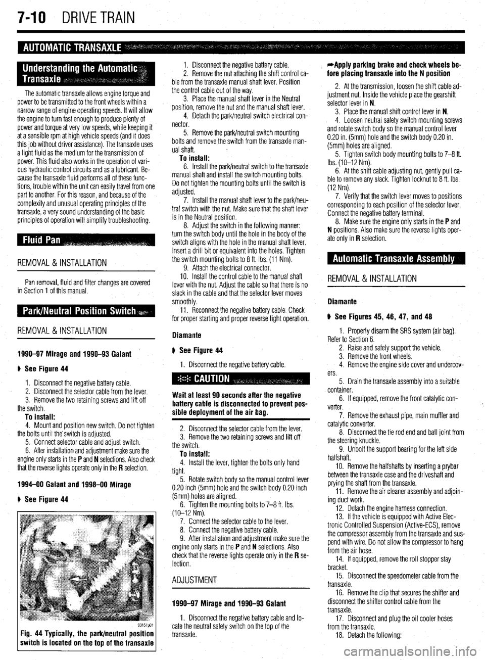
# See Figure 44
1. Disconnect the negative battery cable.
2. Disconnect the selector cable from the lever
3. Remove the two retaining screws and lift off
the switch.
To install: 4. Mount and position new switch. Do not tighten
the bolts until the switch is adjusted.
5. Connect selector cable and adjust switch.
6. After installation and adjustment make sure the
engine only starts in the
P and N selections. Also check
that the reverse lights operate only in the R selectlon.
1994-00 Galant and 1998-00 Mirage
e See Figure 44
93157pm Fig. 44 Typically, the park/neutral position
switch is located on the top of the transaxle
1. Disconnect the negative battery cable.
2. Remove the nut attaching the shift control ca-
ble from the transaxle manual shaft lever. Position
the control cable out of the way.
3. Place the manual shaft lever in the Neutral
position, remove the nut and the manual shaft lever.
4. Detach the park/neutral switch electrical con-
nector.
5. Remove the park/neutral switch mounting
bolts and remove the switch from the transaxle man-
ual shaft.
To install: 6. Install the park/neutral switch to the transaxle
manual shaft and install the switch mounting bolts
Do not tighten the mounting bolts unh the switch is
adjusted.
7. Install the manual shaft lever to the park/neu-
tral switch with the nut. Make sure that the shaft lever
is in the Neutral position.
8. Adjust the switch in the following manner:
turn the switch body until the hole in the body of the
switch aligns with the hole in the manual shaft lever.
Insert a drill bit or equivalent into the holes. Tighten
the switch mounting bolts to 8 ft. Ibs. (11 Nm).
9. Attach the electrical connector.
10. Install the control cable to the manual shaft
lever with the nut. Adjust the cable so that there is no
slack in the cable and that the selector lever moves
smoothly
11. Reconnect the negative battery cable Check
for proper starting and proper reverse light operatron.
Diamante
ti See Figure 44
1. Disconnect the negative battery cable.
Wait at least 90 seconds after the negative
battery cable is disconnected to prevent pos-
sible deployment of the air bag.
2. Disconnect the selector cable from the lever.
3. Remove the two retaining screws and lift off
the switch.
To install: 4. Install the lever, tighten the bolts only hand
tight.
5. Rotate switch body so the manual control lever
0.20 inch (5mm) hole and the switch body 0.20 inch
(5mm) holes are aligned.
6. Tighten the mounting bolts to 7-8 ft. Ibs.
(10-12 Nm).
7. Connect the selector cable to the lever.
8. Connect the negative battery cable.
9. After installahon and adjustment make sure the
engine only starts in the
P and N selections. Also
check that the reverse lights operate only in the R se- lection.
ADJUSTMENT
1990-97 Mirage and 1990-93 Galant
1. Disconnect the negative battery cable and lo-
cate the neutral safety switch on the top of the
transaxle.
*Apply parking brake and chock wheels be-
fore placing transaxle into the N position
2. At the transmission, loosen the shift cable ad-
justment nut. Inside the vehicle place the gearshift
selector lever in N
3. Place the manual shift control lever in N.
4. Loosen neutral safety switch mounhng screws
and rotate switch body so the manual control lever
0.20 in. (5mm) hole and the switch body 0.20 in.
(5mm) holes are aligned.
5. Tighten switch body mounting bolts to 7-8 ft.
Ibs. (lo-12 Nm).
6. At the shift cable adjusting nut, gently pull ca-
ble to remove any slack. Tighten locknut to 8 ft. Ibs.
(12 Nm)
7. Verify that the switch lever moves to positions
corresponding to each position of the selector lever.
Connect the negative battery terminal.
8. Make sure the engine only starts in the
P and
N positions. Also make sure the reverse lights oper-
ate only in
R selection.
REMOVAL&INSTALLATION
Diamante
) See Figures 45, 46, 47, and 48
1. Properly disarm the SRS system (air bag).
Refer to Section 6.
2. Raise and safely support the vehicle.
3. Remove the front wheels.
4. Remove the engine side cover and undercov-
ers.
5. Drain the transaxle assembly into a suitable
container.
6. If equipped, remove the front catalytic con-
verter.
7. Remove the exhaust pipe, main muffler and
catalytic converter.
8. Disconnect the tie rod end and ball joint from
the steering knuckle.
9. Unbolt the support bearing for the left side
halfshaft.
10. Remove the halfshafts by inserting a prybar
between the transaxle case and the driveshaft and
prying the shaft from the transaxle.
11. Remove the air cleaner assembly and adjoin-
ing duct work.
12. Detach the engine harness connection.
13. If the vehicle is equipped with Active Elec-
tronlc Controlled Suspension (Active-ECS), remove
the compressor assembly from the transaxle and sus-
pend with wire. Do not allow the compressor to hang
from the air hose.
14. If equipped, remove the roll stopper stay
bracket.
15. Disconnect the speedometer cable from the
transaxle.
16. Remove the clip that secures the shifter and
disconnect the shifter control cable from the
transaxle.
17. Disconnect and plug the oil cooler hoses
from the transaxle.
18. Detach the following:
Page 334 of 408
- 8-38 SUSPENSION AND STEERING
11. Adjust the power steering belt for proper ten-
sion and tighten the adjusting bolts.
12. Reconnect the negative battery cable.
13. Refill the reservoir and bleed the system.
3. Of EIJGINE
1. Disconnect the battery negative cable. 2. Disconnect the return fluid line. Remove the
reservoir cap and allow the return line to drain the
fluid from the reservoir. If the fluid is contaminated,
disconnect the ignition high tension cable and crank
the engine several times to drain the fluid from the
gear box.
3. Remove the power steering pump drive belt.
4. Remove the pressure switch connector from
the side of the pump.
5. If the alternator is located under the oil pump,
cover it with a shop towel to protect it from oil.
6. Disconnect the high pressure hose and the
return hose from the pump.
7. Remove the pump drive belt and unbolt the
pump from its bracket and remove the pump.
To install: 8. Install the pump, *rap the belt around the
pulley and tighten the bolts that secure the pump to
17 ft. Ibs. (24 Nm).
9. Replace the O-rings and connect the high
pressure hose. Connect the pressure line so the
notch in the fitting aligns and contacts the pump’s
guide bracket. Tighten the mounting nut with lock-
washer to 17 ft. Ibs. (24 Nm).
IO. Using a new hose clamp, connect the return
line.
11. Attach the pressure switch connector.
12. Adjust the belt tension and tighten the
adjust- ing bolts.
13. Refill the reservoir and bleed the system.
Diamante *
FRONT
. 1. Disconnect the battery negative cable. 2. Disconnect the return fluid line. Remove the
reservoir cap and allow the return line to drain the
fluid from the reservoir. If the fluid is contaminated,
disconnect the ignition high tension cable and crank
the engine several times to drain the fluid from the
gearbox.
3. Remove the power steering pump drive belt.
4. Remove the pressure switch connector from
the side of the pump.
5. If the alternator is located under the oil pump,
cover it with a shop towel to protect it from oil.
6. Disconnect the high pressure hose and the
return hose from the pump.
7. Remove the pump drive belt and unbolt the
pump from its bracket and remove the pump.
To install: 8. Install the pump, wrap the belt around the
pulley and tighten the bolts that secure the pump to
17 ft. Ibs. (24 Nm).
9. Replace the O-rings and connect the high
pressure hose. Connect the pressure line so the
notch in the fitting aligns and contacts the pump’s
guide bracket. Tighten the mounting nut with lock-
washer to 17 ft. Ibs. (24 Nm).
10. Using a new hose clamp, connect the return
line.
Il. Attach the pressure switch connector.
12. Adjust the belt tension and tighten the adjust-
ing bolts.
13. Refill the reservoir and bleed the system.
REAR
1. Disconnect the negative battery cable.
2. Drain the power steering fluid.
3. Remove the rear power steering pump heat
protector, located on the engine side of the differen-
tial on the transaxle.
4. Disconnect the pressure line from the pump.
5. Disconnect the suction hose from the pump.
6. Remove the mounting bolts and remove the
pump from the transaxle.
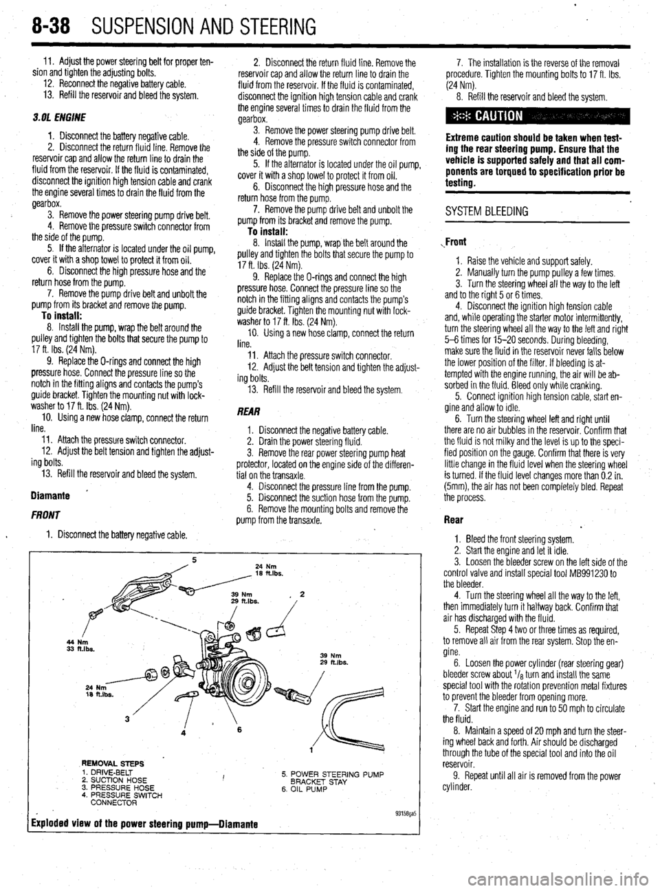
44
33
REMOVAL STEPS
5. POWER STEERING PUMP
BRACKET STAY
6. OIL PUMP 1. DRIVE-BELT
2. SUCTION HOSE I ’ 3. PRESSURE HOSE
4. PRESSURE SWITCH
CONNECTOR
Exploded view of the power steering pump-Diamante
. 93158ga5
7. The installation is the reverse of the removal
procedure. Tighten the mounting bolts to 17 ft. Ibs.
(24 Nm).
8. Refill the reservoir and bleed the system.
Extreme caution should be taken when test-
ing the rear steering pump. Ensure that the
vehicle is supported safely and that all com-
ponents are torqued to specification prior be
testing.
. SYSTEM BLEEDING
,Front
1. Raise the vehicle and support safely.
2. Manually turn the pump pulley a few times.
3. Turn the steering wheel all the way to the left
and to the right 5 or 6 times.
4. Disconnect the ignition high tension cable
and, while operating the starter motor intermittently,
turn the steering wheel all the way to the letI and right
5-6 times for 15-20 seconds. During bleeding,
make sure the fluid in the reservoir never falls below
the lower position of the filter. If bleeding is at-
tempted with the engine running, the air will be ab-
sorbed in the fluid. Bleed only while cranking.
5. Connect ignition high tension cable, start en-
gine and allow to idle.
6. Turn the steering wheel left and right until
there are no air bubbles in the reservoir. Confirm that
the fluid is not milky and the level is up to the speci-
fied position on the gauge. Confirm that there is very
little change in the fluid level when the steering wheel
is turned. If the fluid level changes more than 0.2 in.
(5mm), the air has not been completely bled. Repeat
the process.
Rear
.
1. Bleed the front steering system.
2. Start the engine and let it idle.
3. Loosen the bleeder screw on the left side of the
control valve and install special tool MB991230 to
the bleeder.
4. Turn the steering wheel all the way to the left,
then immediately turn it halfway back. Confirm that
air has discharged with the fluid.
5. Repeat Step 4 two or three times as required,
to remove all air from the rear system. Stop the en-
gine.
6. Loosen the power cylinder (rear steering gear)
bleeder screw about I/* turn and install the same
special tool with the rotation prevention metal fixtures
to prevent the bleeder from opening more.
7. Start the engine and run to 50 mph to circulate
the fluid.
8. Maintain a speed of 20 mph and turn the steer-
ing wheel back and forth. Air should be discharged ,
through the tube of the special tool and into the oil
reservoir.
9. Repeat until all air is removed from the power
cylinder.