1900 MITSUBISHI DIAMANTE key battery
[x] Cancel search: key batteryPage 325 of 408
SUSPENSION AND STEERING 8-29
i ’
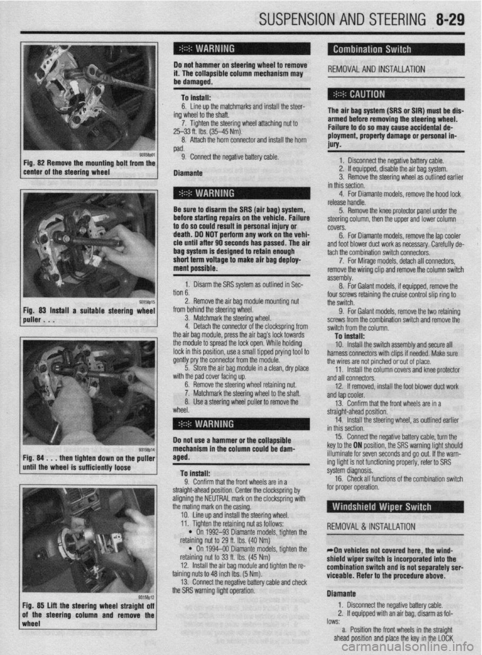
Do not hamme i4 l-ha nnlhnr !r on steering wheel to remove
,,. , II= ,,,,,,Jfble column mechanism may REMOVALANDINSTALLATION
I
be damaged.
To install:
ing
7.
6. Line up the matchmarks and install the steer-
/heel to the shaft.
Tighten the steering wheel attaching nut to
25-33 ft. Ibs. (35-45 Mm).
8. Attach the horn connector and install the horn
pad.
9. Connect the negative battery cable.
Diamante The air bag system (SRS or SIR) must be dis-
armed before removing the steering wheel.
Failure to do so may cause accidental de-
ployment, property damage or personal in-
MY.
1 Rscnnnnd the nnmtivn hattm rJhle . I._“” . ..I_. . ..I *.-~ _...” ““.‘“‘, _““._. 2. If equipped, disable the air bag system.
3. Remove the steering wheel as outlined earlier
in this section.
Be sure to disarm the SRS (air bag
before starting repairs OI
to do so could result in p
death. DO NOT perform ;
cle until after 90 seconds has passed. The ai
bag system is designed to retain enough
short term voltage to make air bag deploy-
ment possible; I) system,
n the vehicle. Failure
lersonal injury or
any work on the vehi-
ir 4. For Diamante models, remove the hood lock
release handle.
5. Remove the knee protector panel under the
steering column, then the upper and lower column
covers.
6. For Diamante models, remove the lap cooler
and foot blower duct work as necessary. Carefully de-
non
b. 1. Disarm the SRS system as outlined in Sec-
. . ^ I assembly. tach the combination switch connecto&.
8. -
7. For Mirage models, detach all connectors,
For Galant models, if equipped, remove the remove the wiring clip and remove the column switch
2. Remove the air bag module mounting nut
from behind the steering wheel.
3. Matchmark the steering wheel.
4. Detach the connector of the clockspring from
the air baq module, press the air baa’s lock towards four screws retaining the cruise control slip ring to
the switch.
9. For Galant models, remove the two retaining
screws from the combination switch and remove the
switch from the column.
Tn install: the modub to spread the lock open:While holding
lock in this position, use a small tipped prying tool to
gently pry the connector from the module.
5. Store the air bag module in a clean, dry place
..# ,I I I .
ut.
Iaft. wlrn me paa cover racmg up.
6. Remove the steering wheel retaining nl
7. Matchmark the steering wheel to the sl
8. Use a steering wheel puller to remove the
wheel. - . . - _-. . _
10. Install the switch assembly and secure all
harness connectors with clips if needed. Make sure
the wires are not pinched orout of place.
11. Install the column covers and knee protector
and all connectors.
12. If removed, install the foot blower duct work
anfl tan cnnler -..- .-
r --- ”
13. Confirm that the front wheels are in a
straight-ahead position.
14. Install the steering wheel, as outlined earlier
in thir
Do not use a hammer or the ~r”---‘~‘- 15. Connect the negative battery cable, turn the
key to the ON position, the SRS warning light should
NW down
rinntlv
wImpl* the puller
iem Fig. 84 . . . then tighte
until the wheel is suffL,,,,, lVvoV
To install:
0 Pnnfirm that thn frnnt whnalc ,?A in , .I. ““llllllll u,a, ,110 ll”lll I.ll~rJlJ CnIj 111 a
straight-ahead position. Center the clockspring by
aligning the NEUTRAL mark on the clockspring with
the mating mark on the casing.
10. Line up and install the steering wheel. illuminate for seven seconds and go out. If the warn-
ing light is not functioning properly, refer to SRS
s’ .’ ystem cllagnosls.
16. Check all functions of the combination switch
for proper operation.
wheel lows:
a. Position the front wheels in the straight
ahead position and place the key in the LOCK
93158p12 Fig. 85 Lift the steering wheel straight off
of the steering column and remove the 11. Tighten the retaining nut as follows:
REMOVAL &INSTALLATION
l On 1992-93 Diamante models, tighten the
nut to 29 ft. Ibs. (40 Nm) retammg I
l On
retaining I
12. lnstal
taining nuts 1
13. Conn
“... . ..” .‘“J...*.” ‘&.“WSJ Y..“.” . ..rn” VII”“..
the SRS warning light operation. 1994-00 Diamante models, tighten the
iut to 33 ft. Ibs. (45 Nm)
II the air bag module and tighten the r&
:o 48 inch Ibs. (5 Nm).
wt the rwnative hatim rahle ami rhwk
*On vehicles not covered here, the wind-
shield wiper switch is incorporated into the
combination switch and is not separately serl
viceable. Refer to the procedure
above.
Diamante
1. Disconnect the negative battery cable.
2. If equipped with an air bag, disarm as fol-
I” .L
Page 326 of 408
8-30 SUSPENSION AND STEERING
position. Remove the key from the ignition lock
cylinder.
b. Disconnect the negative battery cable and
insulate the cable end with high-quality electrical
tape or similar non-conductive wrapping.
c. Wait at least 1 minute before working on
the vehicle. The air bag system is designed to re-
tain enough voltage to deploy the air bag for a
short period of time even after the battery has
been disconnected.
3. Remove the steering wheel. as outlined ear-
lier in this section.
4. Remove the hood lock release handle.
5. Remove the switches from the knee protector
below the steering column, and remove the exposed
retaining screws. Then remove the knee protector.
6. Remove the column covers.
7. Remove necessary duct work and detach the
windshield wiper switch connectors. +
8. Remove the retaining screws and remove the
windshield wiper switch assembly from the steering
column.
To install: 9. Install the wiper switch to the steering col-
umn and connect the connectors.
IO. Install any removed duct work.
11. Install the column covers.
12. Install the knee protector and switches.
13. Install the hood release handle.
14. Confirm that the front wheels are in a straight
ahead position. Install the steering wheel, as outlined
earlier in this section.
15. Connect the negative battery cable and check
the windshield wiper and washer for proper opera-
tion
REMOVAL &INSTALLATION
The air bag system (SRS or SIR) must be dis-
armed before removing the steering wheel.
Failure to do so may cause accidental de-
ployment, property damage or personal in-
jury.
1. If equipped, properly disarm the air bag sys-
tern:
2. Disconnect the negative battery cable.
3. Remove the hood lock release lever from the
lower panel.
4. Remove the lower instrument panel knee pro-
tector.
5. Remove the ductwork with the lower knee
panel and remove the steering wheel assembly.
Use proper steering wheel puller equipment
when removing the steering wheel. The use
of a hammer for removal could damage the
collapsible mechanism within the column.
6. Remove the lower and upper steering column
covers.
7. For Diamante models, remove the lap cooler
and foot shower duct work.
8. If necessary, remove the clip that holds the
wiring harness against the steering column. 9. Detach all necessary connectors.
10. For Galant and Diamante models, remove the
retaining screws, then remove the entire column
switch/clockspring assembly from the left side of the
steering column.
11. For Diarnante models, remove the mounting
screws from the ignition switch and pull the switch
from the interlock cylinder.
12. Insert the key into the steering lock cylinder
and turn to the
ACC position.
13. With a small, pointed tool, push the lock pin
of the steering lock cylinder inward and pull the lock
cylinder out.
14. Remove the key reminder switch, if equipped.
To install: 15. For Mirage, install the lock cylinder in the
lock cylinder bracket. Make sure the cylinder oper-
ates properly before breaking off the heads of the
special bolts, if the bracket was replaced.
16. For Galant and Diarnante models, install the
lock cylinder into the interlock housing. Be sure the
lock pin snaps into place. Install the ignition switch
into the interlock housing. Align the keyway of the ig-
nition switch with the lock cylinder and secure with
the mounting screws.
17. For Galant and Diamante models, install the
column switch/clockspring assembly to the and con-
nect the harness.
18. install the key reminder switch, if equipped.
19. Attach the harness connections and install
the wiring clip.
20. If removed, install the lap cooler and foot
shower duct work.
21. Install the steering column upper and lower
covers.
22. If necessary, install the knee protector and the
steering wheel.
23. Install the hood lock release lever.
24. Connect the negative battery cable, enable the
air bag system, and check the ignition switch and
lock for proper operation.
REMOVALANDINSTALLATION
Mirage and Galant
I. Disconnect the negative battery cable. If
equipped, disarm the air bag system.
2. Remove the hood lock release lever from the
lower panel.
3. Remove the lower instrument panel knee pro-
tector.
4. Remove the ductwork with the lower knee
panel and remove the steering wheel assembly.
*Use proper steering wheel puller equip-
ment when removing the steering wheel. The
use of a hammer for removal could damage
the collapsible mechanism within the col-
umn.
5. Remove the lower steering column cover.
6. Remove the upper steering column cover.
7. Remove the clip that holds the wiring harness
against the steering column.
8. For Galant models, insert the key into the
steering lock cylinder and turn to the ACC position.
9. For Galant models, using a small pointed
tool, push the lock pin of the steering lock cylinder
inward and pull the lock cylinder out. IO. For Galant models, remove the key reminder
switch, if equipped.
11. Unplug the ignition switch harness connec-
tor. Remove the ignition switch mounting screws and
pull the switch from the steering lock cylinder.
*Vehicles equipped with automatic
transaxle have safety-lock systems and will
have a key interlock cable installed in a slide
lever on the side of the key cyfinder. Care-
fully unhook the interlock cable from the lock
cylinder while withdrawing the cylinder from
the lock housing.
To install:
*To remove the steerlng lock, use a hack-
saw or equivalent to cut the special bolts
through the bracket. The bracket and bolts
must be replaced with new ones.
12. With the ignition key removed, install the
slide lever and the interlock cable to the steering lock
cylinder. Apply grease to the interlock cable and in-
stall the cylinder into the lock housing. Check for
normal operation of the interlock system.
13. Install the ignition switch into the rear of the
lock cylinder housing. Be sure to align the keyway of
the ignition switch with interlock cylinder.
14. Attach the harness connections and install
the wiring clip.
15. Install the steering column upper and lower
covers.
16. Install the knee protector.
17. Connect the negative battery cable, enable the
air
bag system (if equipped) and check the ignition
switch and lock for proper operation.
Diamante
Work MUST NOT be started until at least 90
seconds after the ignition switch is turned to
the LOCK position and the negative battery
cable is disconnected from the battery. This
will allow time for the air bag system backup
power supply to deplete its stored energy
preventing accidental air bag deployment
which could result in unnecessary air bag
system repairs and/or personal injury.
I. Disconnect the negative battery cable.
2. Disarm the air bag system, as outlined in
Section 6.
3. Remove the steering wheel, as outlined ear-
lier in this section.
4. Remove the hood lock release handle.
5. Remove the switches from the knee protector
below the steering column and remove the exposed
retaining screws. Then remove the knee protector.
6. Remove the steering column upper and lower
covers. Use care removing the covers to prevent
breakage of alignment tabs.
7. Remove lap cooler and foot shower
duct work. Detach the ignition switch harness connectors.
8. Remove mounting screws from the ignition
switch and pull switch from interlock cylinder.
To install: 9. Install ignition switch into interlock housing.
Align keyway of ignition switch with lock cylinder and
secure with mounting screws.
IO. Connect the ignition switch electrical harness
Plug.
Page 328 of 408
.
8132 SUSPENSION AND STEERING
(42 Nm) on Mirage and 36-39 ft. tbs. (49-53 Nm)
on Galant and Diamante models.
19. Have the front end alignment checked, and
adjusted if necessary.
Inner Tie Rods
11. Loosen the inner tie rod end nut from the
steering gear and remove the inner tie rod end.
To install: 12. Using a new lock plate, install the tie rod end
and tighten the tie rod to 65 ft. Ibs. (90 Nm). REMOVAL &INSTALLATION 13. Bend the tabs of the new lock plate to secure
1. Raise the front of the vehicle and support it
on jackstands.
2. Remove the wheel.
3. Remove the cotter pin and the outer tie rod
ball joint stud nut. Note the position of the steering
linkage.
4. Wire brush the threads on the tie rod shaft
and lubricate with penetrating oil.
5. Using a suitable ball joint separator tool, re-
move the tie rod ball joint from the steering knuckle.
6. Loosen the locknut and remove the tie rod
end from the tie rod. Count the number of complete
turns it takes to completely remove it.
7. Remove the tie rod-to-steering gear locknut.
8. Remove the clamps that secure the flexible
boot to the steering gear.
9. Slide the boot from the inner tie rod and re-
move the boot.
IO. Bend the lock plate tabs from the inner tie rod
end nut. the inner tie rod end.
14. Slide the boot onto the steering gear and se-
cure it with new clamps.
15. Install the outer tie rod end to the steering
gear locknut.
16. Install the outer tie rod end, turning it in ex-
actly as many turns as it was to remove the old one.
Make sure it is correctly positioned in relationship to
the steering linkage.
22. Have a front end alignment performed. 17. Connect the outer tie rod end to the steering
knuckle and install the castle nut. Tighten the nut to
25 ft. Ibs. (34 Nm,) on the Mirage and 21 ft. Ibs. (29
Nm) on the Galant and Diamante models.
18. Install a new cotter pin to the castle nut.
19. Tighten the tie rod end locking nut to 30 ft.
Ibs. (42 Nm) on the Mirage and 36-39 ft. Ibs. (49-53
Nm) on the Galant and Diamante models.
20. Install the wheel and tire assembly.
21. Lower the vehicle.
Mirage
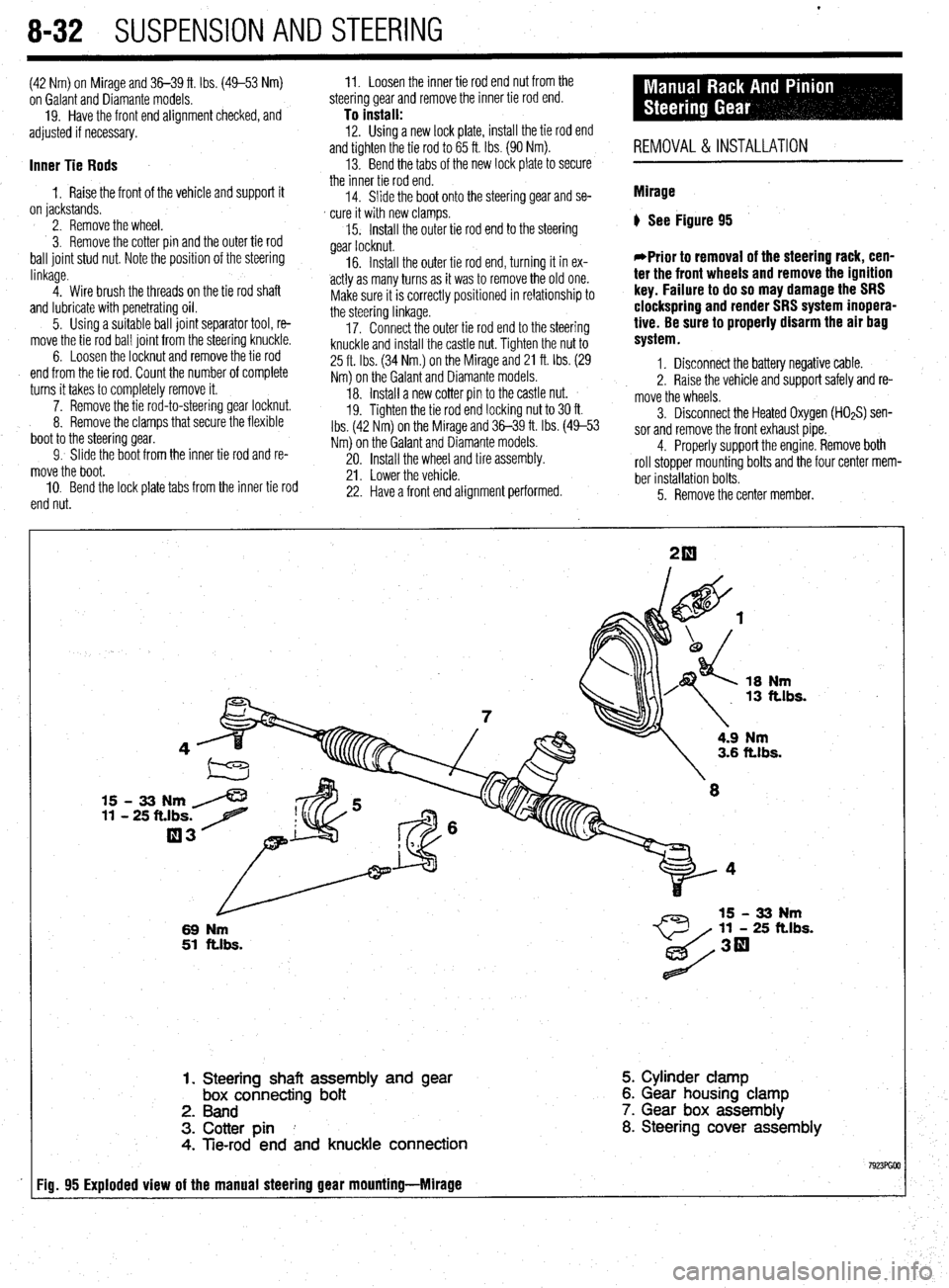
) See Figure 95
*Prior to removal of the steering rack, cen-
ter the front wheels and remove the ignition
key. Failure to do so may damage the SRS
clockspring and render SRS system inopera-
tive. Be sure to properly disarm the air bag
system.
1. Disconnect the battery negative cable.
2. Raise the vehicle and support safely and re-
move the wheels.
5. Remove the center member. 3. Disconnect the Heated Oxygen (HOzS) sen-
sor and remove the front exhaust pipe.
4. Properly support the engine. Remove both
roll stopper mounting bolts and the four center mem-
ber installation bolts.
18
Nm 13 ft.lbs.
15 - 33 Nm /
11 - 25 ft.lbs. 7
03
L
69 Nm
51 ftlbs.
4.9 Nm 3.6 ft.lbs.
11 - 25 ft.lbs.
1. Steering shaft assembly and
gear box connecting bolt
2. Band
3. Cotter pin I
4. Tie-rod end and knuckle connection 5. Cylinder clamp
6. Gear housing clamp
7. Gear box assembly
8. Steering cover assembly
Fig. 95 Exploded view of the manual steering gear mounting-Mlrage
Page 329 of 408
SUSPENSION AND STEERING 8-33
*Matchmark the pinion input shaft of the
rack to the lower steering column joint for in-
stallation purposes.
6. Remove the pinch bolt holding the lower
steering column joint to the rack and pinion input
shaft.
7. Remove the cotter pins and disconnect the tie
rod ends from the steering knuckle.
8. Remove the rack and pinion steering assem-
bly and its rubber mounts from the right side of the
vehicle.
To install: 9. Align the matchmarks of the input shaft and
install the rack to the vehicle.
10. Secure the rack using the retainer clamps and
bolts. Tighten the bolts to 51 ft. Ibs. (70 Nm).
11. Tighten the steering column pinch bolt to 13
ft. Ibs. (18 Nm).
12. Install the center member.
13. Install the front exhaust pipe.
14. Connect the HO$ sensor.
15. Connect the tie rod ends to the steering
knuckles and tighten the castle nuts to 25 ft. Ibs. (34
Nm). Install new cotter pins.
16. Install the wheels and connect the negative
battery cable.
17. Have a front end alignment performed.
REMOVAL &INSTALLATION
Diamante
FRONT
*Prior to removal of the steering gear box,
center the front wheels and remove the igni-
tion key. Failure to do so may damage the
SRS clock spring and render SRS system in-
operative.
1. Disconnect the negative battery cable.
2. Disconnect the front exhaust pipe.
3. If equipped with AWD, remove the transfer
case assembly.
4. Remove the bolt holding the lower steering
column joint to the rack and pinion input shaft.
5. Remove the cotter pins and disconnect the tie
rod ends.
6. Remove the left and right frame members.
7. Remove the stabilizer bar bracket.
8. If equipped with four-wheel steering, discon-
nect the lines going to the rear pump.
9. Remove the rack and pinion steering assem-
bly and its rubber mounts. Move the rack to the right
to remove it from the crossmember.
To install: IO. Install the rack and mounting bolts. Tighten
the bolts to 51 ft. Ibs. (70 Nm). When installing the
rubber rack mounts, align the projection of the
mounting rubber with the indentation in the cross:
member. Install the pinch bolt.
11. Connect the pressure and return lines to the
rack and to the rear pump, if equipped.
12. Install the frame members and tighten the
bolts to 43-51 ft. Ibs. (60-70 Nm).
13. Connect the tie rods and install new cotter
pins. 14. Install the transfer case and front exhaust
pipe.
15. Refill the reservoir and bleed the system.
16. Have a front end alignment performed.
REAR
1. Disconnect the negative battery cable.
2. Raise the vehicle and support safely.
3. Drain the power steering fluid.
4. Remove the main muffler assembly.
5. Remove the rear shock absorber lower
mounting bolts.
6. Using the proper equipment, support the
weight of the rear differential. Remove the 2 small
crossmember brackets.
7. Remove the large self-locking crossmember
mounting nuts on the differential side.
8. Remove the oil line clamp bolts.
9. Remove the pressure tubes.
IO. Hold the tie rod ends stationary and remove
the tie rod end nuts. Remove the tie rod ends from
the trailing arms.
11. Remove the mounting bolts and remove the
rear steering gear.
To install: 12. Secure the unit to the crossmember. Move
the power cylinder piston rod over its full stroke to
determine its neutral position.
13. Align the tie rod ends with the holes in the
trailing arms and install the nuts. Adjust the length of
the tie rods with the nuts if necessary. The difference
in length between the 2 tie rod ends should not ex-
ceed 0.04 in. (1 mm). The nuts’ torque specification is
42 ft. Ibs. (58 Nm).
14. Replace the O-rings and install the pressure
tubes. Clamp in place.
15. Install the large self-locking crossmember
mounting nuts on the differential side. Tighten to
80-94 ft. Ibs. (110-130 Nm).
16. Remove the support equipment.
17. Install the 2 small crossmember brackets.
18. Install the shock mounting bolts.
19. Install the muffler assembly.
20. Refill the reservoir and bleed the system.
21. Have a front end alignment performed. _
Galant
1990-93 MODELS
1. Disconnect the negative battery cable.
2. Drain the power steering fluid.
3. Raise the vehicle and support safely.
4. Remove the bolt holding lower steering col-
umn joint to the rack and pinion input shaft.
5. Remove the transfer case, if equipped.
6. Remove the cotter pins and using the proper
tools, separate the tie rod ends from the steering
knuckle.
7. Locate the triangular brace near the stabilizer
bar brackets on the crossmember and remove both
the brace and the stabilizer bar bracket.
8. Support the center crossmember.
9. Remove the through-bolt from the round roll
stopper and remove the rear bolts from the center
crossmember.
10. Disconnect the front exhaust pipe, if
equipped with FWD.
11. Disconnect the power steering fluid pressure
pipe and return hose from the rack fittings. Plug the
fittings to prevent excess fluid leakage. 12. Lower the crossmember slightly.
13. Remove the rack and pinion steering assem-
bly and its rubber mounts. Move the rack to the right
to remove from the crossmember. Tilt the assembly
downward and remove from the left side of the vehi-
cle. Use caution to avoid damaging the boots.
To install: 14. Install the rack and install the mounting bolts. Tighten the mounting bolts to 43-58 ft. Ibs. (60-80
Nm). When installing the rubber rack mounts, align
the projection of the mounting rubber with the inden-
tation in the crossmember.
15. Connect the power steering fluid lines to the
rack.
16. Connect the exhaust pipe, if removed.
17. Raise the crossmember into position. Install
the center member mounting bolts and tighten to 72
ft. Ibs. (100 Nm). Install the roll stopper bolt and new
nut. Tighten nut to 47 ft. Ibs. (65 Nm).
18. Install the stabilizer bar brackets and brace.
19. Connect the tie rod ends and tighten nuts to
25 ft. Ibs. (34 Nm).
20. Install the transfer case, if removed. Check
and fill fluid.
21. Refill the reservoir with power steering fluid
and bleed the system.
22. Have a front end alignment performed.
1994-M MODELS
+ See Figure 96
Prior to removal of the steering gear box,
center the front wheels and remove the igni-
tion key. Failure to do so may damage the
SRS clock spring and render SRS system in-
operative.
1. Disconnect the negative battery cable.
2. Raise and properly support the vehicle.
3. Remove both front wheel assemblies.
4. Remove the bolt holding lower steering col-
umn joint to the rack and pinion input shaft.
5. Remove the stabilizer bar.
6. Remove the cotter pins, and using joint sepa-
rator MB991 113 or equivalent, disconnect the tie rod
ends from the steering knuckle.
7. On vehicles equipped with Electronic Control
Power steering (EPS), detach the wiring harness from
the solenoid connector.
8. Locate the two triangular braces near the
crossmember and remove both.
9. Support the center crossmember. Remove the
through-bolt from the front round roll stopper and re-
move the bolts securing the center crossmember.
10. Remove the center crossmember. ,
Il. Properly support the engine and remove the
rear roll stopper through-bolt.
12. Disconnect the power steering fluid pressure
pipe and return hose from the rack fittings. Plug the
fittings to prevent excessive fluid leakage.
13. Remove the clamp bolts and the two bolts se-
curing the rack assembly to the chassis.
14. Remove the rack and pinion steering assem-
bly and its rubber mounts.
*When removing the rack and pinion as-
sembly, tilt the assembly to the vehicle side
of the compression lower arm and remove
from the left side of the vehicle.
Page 331 of 408
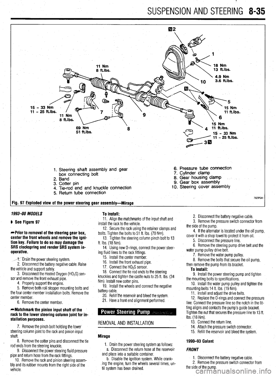
SUSPENSION AND STEERING 8-35
1. Steering shaft assembly and gear
box connecting bolt
2. Band
3. Cotter pin
4. Tie-rod end and knuckle connection
5. Return tube connection 6. Pressure tube connection
7. Cylinder clamp
8. Gear housing clamp
9. Gear box assembly 10. Steering cover assembly
7923PGAl FiD= 97 Exploded view of the power steering gear assembly-Mirage
1993-90 MODELS To install:
) See Figure 97
*Prior to removal of the steering gear box,
center the front wheels and remove the igni-
tion key. Failure to do so may damage the
SRS clockspring and render SRS system in-
operative.
,mr;iin thepower steering system.
2. Disconnect the battery negative cable. Raise
the vehicle and support safely.
3. Disconnect the Heated Oxygen (HOPS) sen-
sor and remove the front exhaust pipe.
4. Properly support the engine.
5. Remove both roll stopper mounting bolts and
the four center member installation bolts. Remove the
center member.
6. Remove the center member. 11. Align the matchmarks of the input shaft and
install the rack to the vehicle.
12. Secure the rack using the retainer clamps and
bolts. Tighten the bolts to 51 ft. Ibs. (70 Nm).
13. Tighten the steering column pinch bolt to 13
ft. Ibs. (18 Nm).
14. Using new O-rings, connect the power steer-
ing fluid lines to the rack fittings.
15. Install the center member.
16. Install the front exhaust pipe.
17. Connect the H02S sensor.
18. Connect the tie rod ends to the steering
knuckles and tighten the castle nuts to 25 ft. Ibs. (34
Nm). Install new cotter pins.
19. Install the wheels and connect the negative
battery cable.
20. Refill ‘the reservoir and bleed the system.
21. Have a front end alignment performed.
stallation purposes. -
7. Remove the pinch bolt holding the lower REMOVALANDINSTALLATION
steering column joint to the rack and pinion input
shaft.
8. Remove the cotter pins and disconnect the tie
rod ends from the steering knuckle.
9. Disconnect the power steering fluid pressure
pipe and return hose from the rack fittings.
IO. Remove the rack and pinion steering assem-
bly and its rubber mounts from the right side of the
vehicle. Mirage
1, Drain the power steering system as follows:
a. Disconnect the return hose at the reservoir
and place into a suitable container.
b. Disable the ignition system. While crank-
ing the engine, turn the wheels several times, un-
til system has been drained. 2. Disconnect the battery negative cable.
3. Remove the pressure switch connector from
the side of the pump.
4. If the alternator is located under the oil pump,
cover it with a shop towel to protect it from oil.
5. Disconnect the pressure line.
6. Remove the steering pump drive belt and the
water pump pulley drive belt.
7. Remove the water pump pulley.
8. Remove the bolts that secure the oil pump,
then remove the pump from its bracket.
To install: 9. Install the power steering pump and tighten
the mounting bolts to specifications.
IO. Install the water pump pulley and tighten the
mounting bolts 14 ft. Ibs. (19 Nm).
11. Install and adjust the drive belts.
12. Replace the O-rings and connect the pressure
line. Connect the pressure line so the notch in the fit-
ting aligns and contacts the pump’s guide bracket.
Tighten the nut that secures the pressure line to 13 ft.
Ibs. (18 Nm).
13. Connect the return line.
14. Attach the pressure switch connector.
15. Refill the reservoir and bleed the system.
1990-93 Galant
FRONT
1. Disconnect the battery negative cable.
2. Remove the pressure switch connector from
the side of the pump.
Page 339 of 408
BRAKiS 9-3
simple and efficient. A vacuum diaphragm is located gine. Have an assistant observe the brake lights at the
on the front of the master cylinder and assists the dri- rear of the vehicle while you push on the brake pedal.
ver in applying the brakes, reducing both the effort The lights should come on just as the brake pedal
and travel he must put into moving the brake pedal. passes the point of free play.
The vacuum diaphragm housing is normally con- 9.
Adjust the brake light switch as necessary. The
netted to the intake manifold by a vacuum hose. A small amount of free play in the
pedal should not
check valve is placed at the point where the hose en-
ters the diaphragm housing, so that during periods
Of low manifold vacuum brakes assist will not be lost.
Depressing the brake pedal closes off the vacuum
source and allows atmospheric pressure to enter on
one side of the diaphragm. This causes the master
cylinder pistons to move and apply the brakes. When
the brake pedal is released, vacuum is applied to
REMOVAL &INSTALLATION
both sides of the diaphragm and springs return the
diaphragm and master cylinder pistons to the re- ) See Figures 2 thru 10
leased position.
If the vacuum supply fails, the brake pedal rod will
contact the end of the master cylinder actuator rod
and the system will apply the brakes without any
power assistance. The driver will notice that much
higher pedal effort is needed to stop the car and that
the pedal feels harder than usual.
Vacuum leak Test
1. Operate the engine at idle without touching the
brake pedal for at least one minute.
2. Turn off the engine and wait one minute.
3. Test for the presence of assist vacuum by de-
pressing the brake pedal and releasing it several
3 MASTER N- 188A11Ly
times. If vacuum is present in the system, light appli- . KLNsIMEm 0s CLWRANCE
BETWEEN BRAKE WOSTER
cation will produce less and less pedal travel. If there PUSHROO AN0 PRIMARY PISTCU
is no vacuum, air is leaking into the system.
System Operation Test
1. With the engine OFF, pump the brake pedal
until the supply vacuum is entirely gone.
2. Put light, steady pressure on the brake pedal.
3. Start the engine and let it idle. If the system is
operating correctly, the brake pedal should fall to-
ward the floor if the constant pressure is maintained.
Power brake systems may be tested for hydraulic
leaks just as ordinary systems are tested.
REMOVAL&INSTALLATION
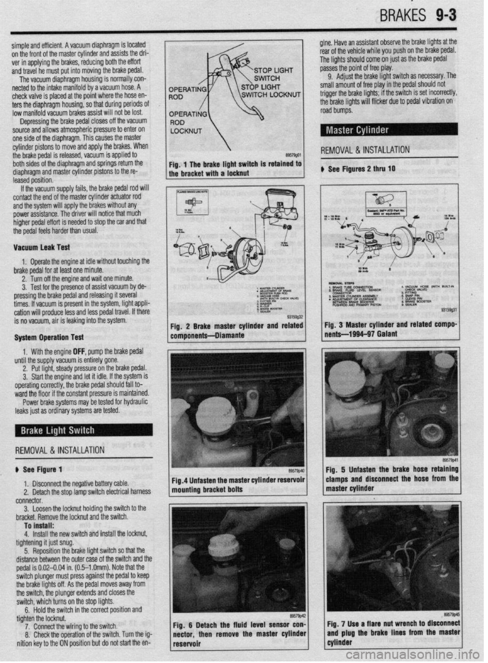
$ See Figure 1
1. Disconnect the negative battery cable.
2. Detach the stop lamp switch electrical harness
connector.
3. Loosenthe locknut holding the switch to the
bracket. Remove the locknut and the switch.
To install:
4.
Install the new switch and install the locknut,
tightening it just snug.
5. Reposition the brake light switch so that the
distance between the outer case of the switch and the
pedal is 0.02-0.04 in. (0.5-l .Omm). Note that the
switch plunger must press against the pedal to keep
the brake lights off. As the pedal moves away from
the switch, the plunger extends and closes the
switch, which turns on the stop lights.
6.
Hold the switch in the correct position and
tighten the locknut.
7. Connect the wiring to the switch.
8. Check the operation of the switch. Turn the ig-
nition key to the ON position but do not start the en-
Page 340 of 408
9-4 BRAKES
Fig 8 Unfasten the master cylinder-to-
power booster retaining nuts . . . F57g’6~ Fig. 9 . . . then remove the master cylinder
assembly from the vehicle Fig. 10 The brake booster pushrod and prf-
mary piston clearance (A) must be adjusted
1. Disconnect the negative battery cable.
2. Remove the master cylinder reservoir cap,
then use a clean turkey baster or equivalent to siphon
out as much fluid as possible and place in a suitable
container. Install the cap.
Brake fluid contains polyglycol ethers and
polyglycols. Avoid contact with the eyes and
wash your hands thoroughly after handling
brake fluid. If you do get brake fluid in your
eyes, flush your eyes with clean, running wa-
ter for 15 minutes. If eye irritation persists,
or if you have taken brake fluid internally,
IMMEDIATELY seek medical assistance.
3. Disconnect and plug the lines from the brake
master cylinder reservoir.
4. Detach the fluid level sensor connector, un-
fasten the retainers, then remove the master cylinder
reservoir.
5. For vehicles equipped with manual transaxle,
remove the clutch master cylinder reservoir bracket.
6. Disconnect and plug the brake lines from the
master cylinder.
7. Unfasten the master cylinder-to-power
booster retainino nuts, then remove the master cvlin- ante value will become 0.004-0.012 in.
(0.1-0.3mm).
9. install the master cylinder to the brake
booster, then install the retaining nuts. Tighten the
nuts to 7 ft. Ibs. (10 Nm).
10. Install the master cylinder reservoir, securing
the retainers.
11. Attach the fluid level sensor connector, then
unplug and connect the fluid lines to the reservoir.
12. The remainder of installation is the reverse of
the removal procedure. Fill the reservoir with the
proper type and amount of DOT 3 brake fluid from a
fresh, sealed container.
I l
Clean, high quality brake fluid is essential to
the safe and proper operation of the brake
system. You should always buy the highest
quality brake fluid that is available. If the
brake fluid becomes contaminated, drain and
flush the system, then refill the master cylin-
der with new fluid. Never reuse any brake
fluid. Any brake fluid that is removed from
the system should be discarded. Also, do not
allow any brake fluid to come in contact with
a painted surface; it will damage the paint. Measure the brake pedal height from the floor of
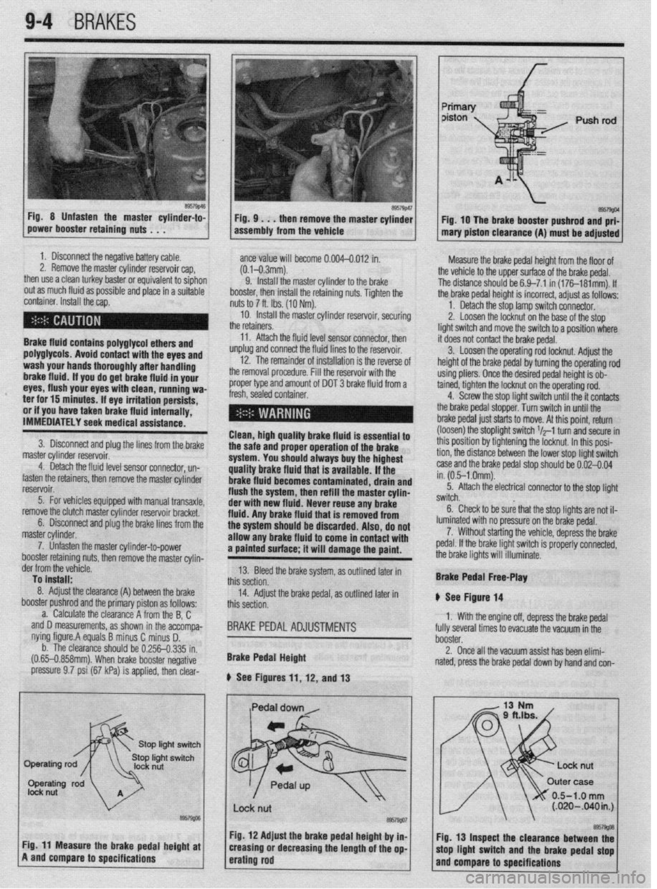
the vehicle to the upper surface of the brake pedal.
The distance should be 6.9-7.1 in (176181mm). If
the brake pedal height is incorrect, adjust as follows:
1. Detach the stop lamp switch connector.
2. Loosen the locknut on the base of the stop
light switch and move the switch to a position where
it does not contact the brake pedal.
3. Loosen the operating rod locknut. Adjust the
height of the brake pedal by turning the operating rod
using pliers. Once the desired pedal height is ob-
tained, tighten the locknut on the operating rod.
4. Screw the stop light switch until the it contacts
the brake pedal stopper. Turn switch in until the
brake pedal just starts to move. At this point, return
(loosen) the stoplight switch $-1 turn and secure in
this position by tightening the locknut. In this posi-
tion, the distance between the lower stop light switch
case and the brake pedal stop should be 0.02-0.04
in. (0.5-l .Omm).
5. Attach the electrical connector to the stop light
switch.
6. Check to be sure that the stop lights are not il-
luminated with no pressure on the brake pedal.
7. Without starting the vehicle, depress the brake
pedal. If the brake light switch is properly connected,
the brake lights will illuminate.
der from the vefiicle.
To install:
8. Adjust the clearance (A)
booster pushrod ant
a. Calculate tl -,
between the brake
I the primary piston as follows:
le clearance A from the B, C
accompa-
i D.
I.335 in.
negative and D measurements, as shown in the
nying figure.A equals B minus C minus
b. The clearance should be 0.256-t
(0.65-0.858mm). When brake booster I
pressure 9.7 psi (67 kPa) is applied, then clear- 13. Bleed the brake system, as outlined later in
this section.
14. Adjust the brake pedal, as outlined later in
this section.
BRAKE PEDAL ADJUSTMENTS
Brake Pedal Height
b See Figures 11, 12, and 13 Brake Pedal Free-Play
II See Figure 14
1. With the engine off, depress the brake pedal
fully several times to evacuate the vacuum in the
booster.
2. Once all the vacuum assist has been elimi-
nated, press the brake pedal down by hand and con-
/
0.5-1.0 mm (.020-B40in.J I
I
I I
Fig. 12 Adjust the brake pedal height by in- I I.
@57w
Cir 44 “a*., .._^ *I.- 9.--l,- ---I-* L-@-L. -I Fig. 13 Inspect the clearance between thf . . - _-.L -*.a- - . . * _ . . . . ._ . rly. I I rnca~urc we urime peoai nefgnr ar
A and compare to specifications creasmg or aecreasing the lengrn or me op-
erating rod mop llgnt WItCh arm the brake pedal stop
and compare to specifications
Page 388 of 408
II-6 TROUBLESHOOTING
DIAGhUSTIC PROCEDURES
Gasoline Engines
1. Engine turns over, but wilt not start
a. Check fuel level in fuel tank, add fuel if empty.
b. Check battery condition and state of charge. If voltage and load test below specifica-
tion, charge or replace battery.
c. Check battery terminal and cable condition and tightness. Clean terminals and replace
damaged, worn or corroded cables.
d. Check fuel delivery system. If fuel is not reaching the fuel injectors, check for a loose
electrical connector or defective fuse, relay or fuel pump and replace as necessary.
e. Engine may have excessive wear or mechanical damage such as low cylinder cranking
pressure, a broken camshaft drive system, insufficient valve clearance or bent valves.
f. Check for fuel contamination such as water in the fuel. During winter months, the wa-
ter may freeze and cause a fuel restriction. Adding a fuel additive may help, however
the fuel system may require draining and purging with fresh fuel.
g. Check for ignition system failure. Check for loose or shorted wires or damaged igni-
tion system components. Check the spark plugs for excessive wear or incorrect elec-
trode gap. If the problem is worse in wet weather, check for shorts between the spark
plugs and the ignition coils.
h. Check the engine management system for a failed sensor or control module.
2. Engine does not turn over when attempting to start
a. Check the battery state of charge and condition. If the dash lights are not visible or
very dim when turning the ignition key on, the battery has either failed internally or
discharged, the battery cables are loose, excessively corroded or damaged, or the al-
ternator has failed or internally shorted, discharging the battery. Charge or replacethe
battery, clean or replace the battery cables, and check the alternator output.
b. Check the operation of the neutral safety switch. On automatic transmission vehicles,
try starting the vehicle in both Park and Neutral. On manual transmission vehicles, de-
press the clutch pedal and attempt to start. On some vehicles, these switches can be
adjusted. Make sure the switches or wire connectors are not loose or damaged. Re-
place or adjust the switches as necessary.
c. Check the starter motor, starter solenoid or relay, and starter motor cables and wires.
Check the ground from the engine to the chassis. Make sure the wires are not loose,
damaged, or corroded. If battery voltage is present at the starter relay, try using a re-
mote starter to start the vehicle for test purposes only. Replace any damaged or cor-
roded cables, in addition to replacing any failed components.
d. Check the engine for seizure. If the engine has not been started for a long period of
time, internal parts such as the rings may have rusted to the cylinder walls. The engine
may have suffered internal damage, or could be hydro-locked from ingesting water.
Remove the spark plugs and carefully attempt to rotate the engine using a suitable
breaker bar and socket on the crankshaft pulley. If the engine is resistant to moving, or
moves slightly and then binds, do not force the engine any further before determining
the problem.
3. Enpine stalls immediately when started
a. Check the ignition switch condition and operation. The electrical contacts in the run
position may be worn or damaged. Try restarting the engine with all electrical acces-
sories in the off position. Sometimes turning the key on an off will help in emergency
situations, however once the switch has shown signs of failure, it should be replaced
as soon as possible.
b. Check for loose, corroded, damaged or shorted wires for the ignition system and re-
pair or replace.
c. Check for manifold vacuum leaks or vacuum hose leakage and repair or replace parts
as necessary.
d. Measure the fuel pump delivery volume and pressure. Low fuel pump pressure can
also be noticed as a lack of power when accelerating. Make sure the fuel pump lines
are not restricted. The fuel pump output is not adjustable and requires fuel pump re-
placement to repair.
e. Check the engine fuel and ignition management system. Inspect the sensor wiring and
electrical connectors. A dirty, loose or damaged sensor or control module wire can
simulate a failed component.
f. Check the exhaust system for internal restrictions.
4. Starter motor spins, but does not engage
a. Check the starter motor for a seized or binding pinion gear.
b. Remove the flywheel inspection plate and check for a damaged ring gear.
5. Engine is difficult to start when Gold
a. Check the battery condition, battery state of charge and starter motor current draw. Re-
place the battery if marginal and the starter motor if the current draw is beyond specifi-
cation. b. Check the battery cable condition. Clean the battery terminals and replace corroded or
damaged cables.
c. Check the fuel system for proper operation. A fuel pump with insufficient fuel pressure
or clogged injectors should be replaced.
d. Check the engine’s tune-up status. Note the tune-up specifications and check for items
such as severely worn spark plugs; adjust or replace as needed. On vehicles with
manually adjusted valve clearances, check for tight valves and adjust to specification.
e. Check for a failed coolant temperature sensor, and replace if out of specification.
f. Check the operation of the engine management systems for fuel and ignition; repair or
replace failed components as necessary.
6. En#ine is ditticutt to start when hot
a. Check the air filter and air intake system. Replace the air filter if it is dirty or contami-
nated. Check the fresh air intake system for restrictions or blockage.
b. Check for loose or deteriorated engine grounds and clean, tighten or replace as
needed.
c. Check for needed maintenance. Inspect tune-up and service related items such as
spark plugs and engine oil condition, and check the operation of the engine fuel and
ignition management system.
Diesel Engines
1. Engine turns over but won’t start
a. Check engine starting procedure and restart engine.
b. Check the glow plug operation and repair or replace as necessary.
c. Check for air in the fuel system or fuel filter and bleed the air as necessary.
d. Check the fuel delivery system and repair or replace as necessary.
e. Check fuel level and add fuel as needed.
f. Check fuel quality. If the fuel is contaminated, drain and flush the fuel tank.
g. Check engine compression. If compression is below specification, the engine may
need to be renewed or replaced.
h. Check the injection pump timing and set to specification.
i. Check the injection pump condition and replace as necessary.
j. Check the fuel nozzle operation and condition or replace as necessary.
2. Engine does
hot turn over when attempting to start
a. Check the battery state of charge and condition. If the dash lights are not visible or
very dim when turning the ignition key on, the battery has either failed internally or
discharged, the battery cables are loose, excessively corroded or damaged, or the al-
ternator has failed or internally shorted, discharging the battery. Charge or replace the
battery, clean or replace the battery cables, and check the alternator output.
b. Check the operation of the neutral safety switch. On automatic transmission vehicles,
try starting the vehicle in both Park and Neutral. On manual transmission vehicles, de-
press the clutch pedal and attempt to start. On some vehicles, these switches can be
adjusted. Make sure the switches or wire connectors are not loose or damaged. Re-
place or adjust the switches as necessary.
c. Check the starter motor, starter solenoid or relay, and starter motor cables and wires.
Check the ground from the engine to the chassis. Make sure the wires are not loose,
damaged, or corroded. If battery voltage is present at the starter relay, try using a re-
mote starter to start the vehicle for test purposes only. Replace any damaged or cor-
roded cables, in addition to replacing any failed components.
d. Check the engine for seizure. If the engine has not been started for a long period of
time, internal parts such as the rings may have rusted to the cylinder walls. The engine
may have suffered internal damage, or could be hydro-locked from ingesting water.
Remove the injectors and carefully attempt to rotate the engine using a suitable
breaker bar and socket on the crankshaft pulley. If the engine is resistant to moving, or
moves slightly and then binds, do not force the engine any further before determining
the cause of the problem.
3. Engine stalls afier starting
a. Check for a restriction in the fuel return line or the return line check valve and repair as
necessary.
b. Check the glow plug operation for turning the glow plugs off too soon and repair as
necessary.
c. Check for incorrect injection pump timing and reset to specification.
d. Test the engine fuel pump and replace if the output is below specification.
e. Check for contaminated or incorrect fuel. Completely flush the fuel system and replace
with fresh fuel.
f. Test the engine’s compression for low compression. If below specification, mechanical
repairs are necessary to repair.
g. Check for air in the fuel. Check fuel tank fuel and fill as needed.
h. Check for a failed injection pump. Replace the pump, making sure to properly set the
pump timing.