1900 MITSUBISHI DIAMANTE warning
[x] Cancel search: warningPage 325 of 408
SUSPENSION AND STEERING 8-29
i ’
Do not hamme i4 l-ha nnlhnr !r on steering wheel to remove
,,. , II= ,,,,,,Jfble column mechanism may REMOVALANDINSTALLATION
I
be damaged.
To install:
ing
7.
6. Line up the matchmarks and install the steer-
/heel to the shaft.
Tighten the steering wheel attaching nut to
25-33 ft. Ibs. (35-45 Mm).
8. Attach the horn connector and install the horn
pad.
9. Connect the negative battery cable.
Diamante The air bag system (SRS or SIR) must be dis-
armed before removing the steering wheel.
Failure to do so may cause accidental de-
ployment, property damage or personal in-
MY.
1 Rscnnnnd the nnmtivn hattm rJhle . I._“” . ..I_. . ..I *.-~ _...” ““.‘“‘, _““._. 2. If equipped, disable the air bag system.
3. Remove the steering wheel as outlined earlier
in this section.
Be sure to disarm the SRS (air bag
before starting repairs OI
to do so could result in p
death. DO NOT perform ;
cle until after 90 seconds has passed. The ai
bag system is designed to retain enough
short term voltage to make air bag deploy-
ment possible; I) system,
n the vehicle. Failure
lersonal injury or
any work on the vehi-
ir 4. For Diamante models, remove the hood lock
release handle.
5. Remove the knee protector panel under the
steering column, then the upper and lower column
covers.
6. For Diamante models, remove the lap cooler
and foot blower duct work as necessary. Carefully de-
non
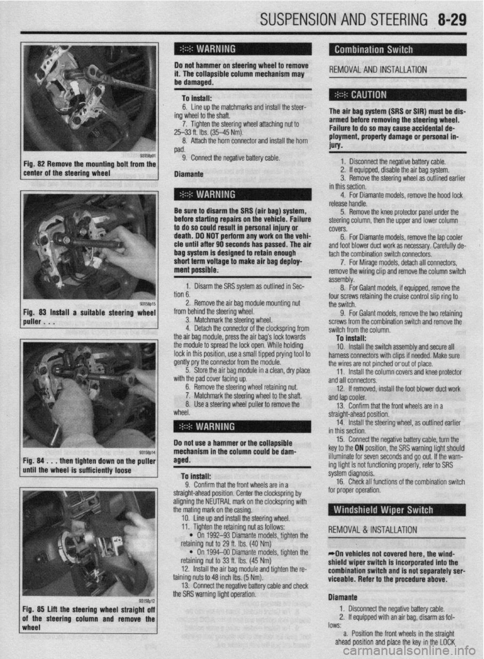
b. 1. Disarm the SRS system as outlined in Sec-
. . ^ I assembly. tach the combination switch connecto&.
8. -
7. For Mirage models, detach all connectors,
For Galant models, if equipped, remove the remove the wiring clip and remove the column switch
2. Remove the air bag module mounting nut
from behind the steering wheel.
3. Matchmark the steering wheel.
4. Detach the connector of the clockspring from
the air baq module, press the air baa’s lock towards four screws retaining the cruise control slip ring to
the switch.
9. For Galant models, remove the two retaining
screws from the combination switch and remove the
switch from the column.
Tn install: the modub to spread the lock open:While holding
lock in this position, use a small tipped prying tool to
gently pry the connector from the module.
5. Store the air bag module in a clean, dry place
..# ,I I I .
ut.
Iaft. wlrn me paa cover racmg up.
6. Remove the steering wheel retaining nl
7. Matchmark the steering wheel to the sl
8. Use a steering wheel puller to remove the
wheel. - . . - _-. . _
10. Install the switch assembly and secure all
harness connectors with clips if needed. Make sure
the wires are not pinched orout of place.
11. Install the column covers and knee protector
and all connectors.
12. If removed, install the foot blower duct work
anfl tan cnnler -..- .-
r --- ”
13. Confirm that the front wheels are in a
straight-ahead position.
14. Install the steering wheel, as outlined earlier
in thir
Do not use a hammer or the ~r”---‘~‘- 15. Connect the negative battery cable, turn the
key to the ON position, the SRS warning light should
NW down
rinntlv
wImpl* the puller
iem Fig. 84 . . . then tighte
until the wheel is suffL,,,,, lVvoV
To install:
0 Pnnfirm that thn frnnt whnalc ,?A in , .I. ““llllllll u,a, ,110 ll”lll I.ll~rJlJ CnIj 111 a
straight-ahead position. Center the clockspring by
aligning the NEUTRAL mark on the clockspring with
the mating mark on the casing.
10. Line up and install the steering wheel. illuminate for seven seconds and go out. If the warn-
ing light is not functioning properly, refer to SRS
s’ .’ ystem cllagnosls.
16. Check all functions of the combination switch
for proper operation.
wheel lows:
a. Position the front wheels in the straight
ahead position and place the key in the LOCK
93158p12 Fig. 85 Lift the steering wheel straight off
of the steering column and remove the 11. Tighten the retaining nut as follows:
REMOVAL &INSTALLATION
l On 1992-93 Diamante models, tighten the
nut to 29 ft. Ibs. (40 Nm) retammg I
l On
retaining I
12. lnstal
taining nuts 1
13. Conn
“... . ..” .‘“J...*.” ‘&.“WSJ Y..“.” . ..rn” VII”“..
the SRS warning light operation. 1994-00 Diamante models, tighten the
iut to 33 ft. Ibs. (45 Nm)
II the air bag module and tighten the r&
:o 48 inch Ibs. (5 Nm).
wt the rwnative hatim rahle ami rhwk
*On vehicles not covered here, the wind-
shield wiper switch is incorporated into the
combination switch and is not separately serl
viceable. Refer to the procedure
above.
Diamante
1. Disconnect the negative battery cable.
2. If equipped with an air bag, disarm as fol-
I” .L
Page 338 of 408
9-2 BRAKES
Hydraulic systems are used to actuate the brakes
of all modern automobiles. The system transports the
power required to force the frictional surfaces of the
braking system together from the pedal to the indi-
vidual brake units at each wheel. A hydraulic system
is used for two reasons.
First, fluid under pressure can be carried to all
parts of an automobile by small pipes and flexible
hoses without taking up a significant amount of room
or posing routing problems.
Second, a great mechanical advantage can be
given to the brake pedal end of the system, and the
foot pressure required to actuate the brakes can be
reduced by making the surface area of the master
cylinder pistons smaller than that of any of the pis-
tons in the wheel cylinders or calipers.
The master cylinder consists of a fluid reservoir
along with a double cylinder and piston assembly.
Double type master cylinders are designed to sepa-
rate the front and rear braking systems hydraulically
in case of a leak. The master cylinder converts me-
chanical motion from the pedal into hydraulic pres-
sure within the lines. This pressure is translated back
into mechanical motion at the wheels by either the
wheel cylinder (drum brakes) or the caliper (disc
brakes).
Steel lines carry the brake fluid to a point on the
vehicle’s frame near each of the vehicle’s wheels. The
fluid is then carried to the calipers and wheel cylin-
ders by flexible tubes in order to allow for suspen-
sion and steering movements.
In drum brake systems, each wheel cylinder con-
tains two pistons, one at either end, which push out-
ward in opposite directions and force the brake shoe
into contact with the drum.
In disc brake systems, the cylinders are part of the
calipers. At least one cylinder in each caliper is used
to force the brake pads against the disc.
All pistons employ some type of seal, usually
made of rubber, to minimize fluid leakage. A rubber
dust boot seals the outer end of the cylinder against
dust and dirt. The boot fits around the outer end of
the piston on disc brake calipers, and around the
brake actuating rod on wheel cylinders.
The hydraulic system operates as follows: When at
rest, the entire system, from the piston(s) in the mas-
ter cylinder to those in the wheel cylinders or
calipers, is full of brake fluid. Upon application of the
brake pedal, fluid trapped in front of the master cylin-
der piston(s) is forced through the lines to the wheel
cylinders. Here, it forces the pistons outward, in the
case of drum brakes, and inward toward the disc, in
the case of disc brakes. The motion of the pistons is
opposed by return springs mounted outside the
cylinders in drum brakes, and by spring seals, in disc
brakes.
Upon release of the brake pedal, a spring located
inside the master cylinder immediately returns the
master cylinder pistons to the normal position. The
pistons contain check valves and the master cylinder
I
has compensating ports drilled in it. These are un-
covered as the pistons reach their normal position.
The piston check valves allow fluid to flow toward the
wheel cylinders or calipers as the pistons withdraw.
Then, as the return springs force the brake pads or
shoes into the released position, the excess fluid
reservoir through the compensating ports. It is during the time the pedal is in the released position that any
fluid that has leaked out of the system will be re-
placed through the compensating ports.
Dual circuit master cylinders employ two pistons,
located one behind the other, in the same cylinder.
The primary piston is actuated directly by mechanical
linkage from the brake pedal through the power
booster. The secondary piston is actuated by fluid
trapped between the two pistons. If a leak develops in
front of the secondary piston, it moves forward until it
bottoms against the front of the master cylinder, and
the fluid trapped between the pistons will operate the
rear brakes. If the rear brakes develop a leak, the pri-
mary piston will move forward until direct contact
with the secondary piston takes place, and it will
force the secondary piston to actuate the front brakes.
In either case, the brake pedal moves farther when the
brakes are applied, and less braking power is avail-
able.
All dual circuit systems use a switch to warn the
driver when only half of the brake system is opera-
tional. This switch is usually located in a valve body
which is mounted on the firewall or the frame below
the master cylinder. A hydraulic piston receives pres-
sure from both circuits, each circuits pressure being
applied to one end of the piston. When the pressures
are in balance, the piston remains stationary. When
one circuit has a leak, however, the greater pressure
in that circuit during application of the brakes will
push the piston to one side, closing the switch and
activating the brake warning light.
In disc brake systems, this valve body also con-
tains a metering valve and, in some cases, a propor-
tioning valve. The metering valve keeps pressure
from traveling to the disc brakes on the front wheels
until the brake shoes on the rear wheels have con-
tacted the drums, ensuring that the front brakes will
never be used alone. The proportioning valve con-
trols the pressure to the rear brakes to lessen the
chance of rear wheel lock-up during very hard brak-
ing.
Warning lights may be tested by depressing the
brake pedal and holding it while opening one of the
wheel cylinder bleeder screws. If this does not cause
the light to go on, substitute a new lamp, make conti-
nuity checks, and, finally, replace the switch as nec-
essary.
The hydraulic system may
be checked for leaks by applying pressure to the pedal gradually and steadily.
If the pedal sinks very slowly to the floor, the system
has a leak. This is not to be confused with a springy
or spongy feel due to the compression of air within
the lines. If the system leaks, there will be a gradual
change in the position of the pedal with a constant
pressure.
Check for leaks along all lines and at wheel cylin-
ders. If no external leaks are apparent, the problem is
inside the master cylinder,
DISC BRAKES
Instead of the traditional expanding brakes that
press outward against a circular drum, disc brake
systems utilize a disc (rotor) with brake pads posi-
tioned on either side of it. An easily-seen analogy is
the hand brake arrangement on a bicycle. The pads
squeeze onto the rim of the bike wheel, slowing its
motion. Automobile disc brakes use the identical principle but apply the braking effort to a separate
disc instead of the wheel.
The disc (rotor) is a casting, usually equipped with
cooling fins between the two braking surfaces. This
enables air to circulate between the braking surfaces
making them less sensitive to heat buildup and more
resistant to fade. Dirt and water do not drastically af-
fect braking action since contaminants are thrown off
by the centrifugal action of the rotor or scraped off
the by the pads. Also, the equal clamping action of
the two brake pads tends to ensure uniform, straight
line stops. Disc brakes are inherently self-adjusting.
There are three general types of disc brake:
1. A fixed caliper.
2. A floating caliper.
3. A sliding caliper.
The fixed caliper design uses two pistons
mounted on either side of the rotor (in each side of
the caliper). The caliper is mounted rigidly and does
not move.
The sliding and floating designs are quite similar.
In fact, these two types are often lumped together. In
both designs, the pad on the inside of the rotor is
moved into contact with the rotor by hydraulic force.
The caliper, which is not held in a fixed position,
moves slightly, bringing the outside pad into contact
with the rotor. There are various methods of attaching
floating calipers. Some pivot at the bottom or top,
and some slide on mounting bolts. In any event, the
end result is the same.
DRUM BRAKES
Drum brakes employ two brake shoes mounted on
a stationary backing plate. These shoes are posi-
tioned inside a circular drum which rotates with the
wheel assembly. The shoes are held in place by
springs. This allows them to slide toward the drums
(when they are applied) while keeping the linings and
drums in alignment. The shoes are actuated by a
wheel cylinder which is mounted at the top of the
backing plate. When the brakes are applied, hydraulic
pressure forces the wheel cylinder’s actuating links
outward. Since these links bear directly against the
top of the brake shoes, the tops of the shoes are then
forced against the inner side of the drum. This action
forces the bottoms of the two shoes to contact the
brake drum by rotating the entire assembly slightly
(known as servo action). When pressure within the
wheel cylinder is relaxed, return springs pull the
shoes back away from the drum.
Most modern drum brakes are designed to self-
adjust themselves during application when the vehi-
cle is moving in reverse. This motion causes both
shoes to rotate very slightly with the drum, rocking
an adjusting lever, thereby causing rotation of the ad-
justing screw. Some drum brake systems are de-
signed to self-adjust during application whenever the
brakes are applied. This on-board adjustment system
reduces the need for maintenance adjustments and
keeps both the brake function and pedal feel satisfac-
tory.
POWER BOOSTERS
Virtually all modern vehicles use a vacuum as-
sisted power brake system to multiply the braking
force and reduce pedal effort. Since vacuum is always
available when the engine is operating, the system is
Page 361 of 408
BRAKES 9-25
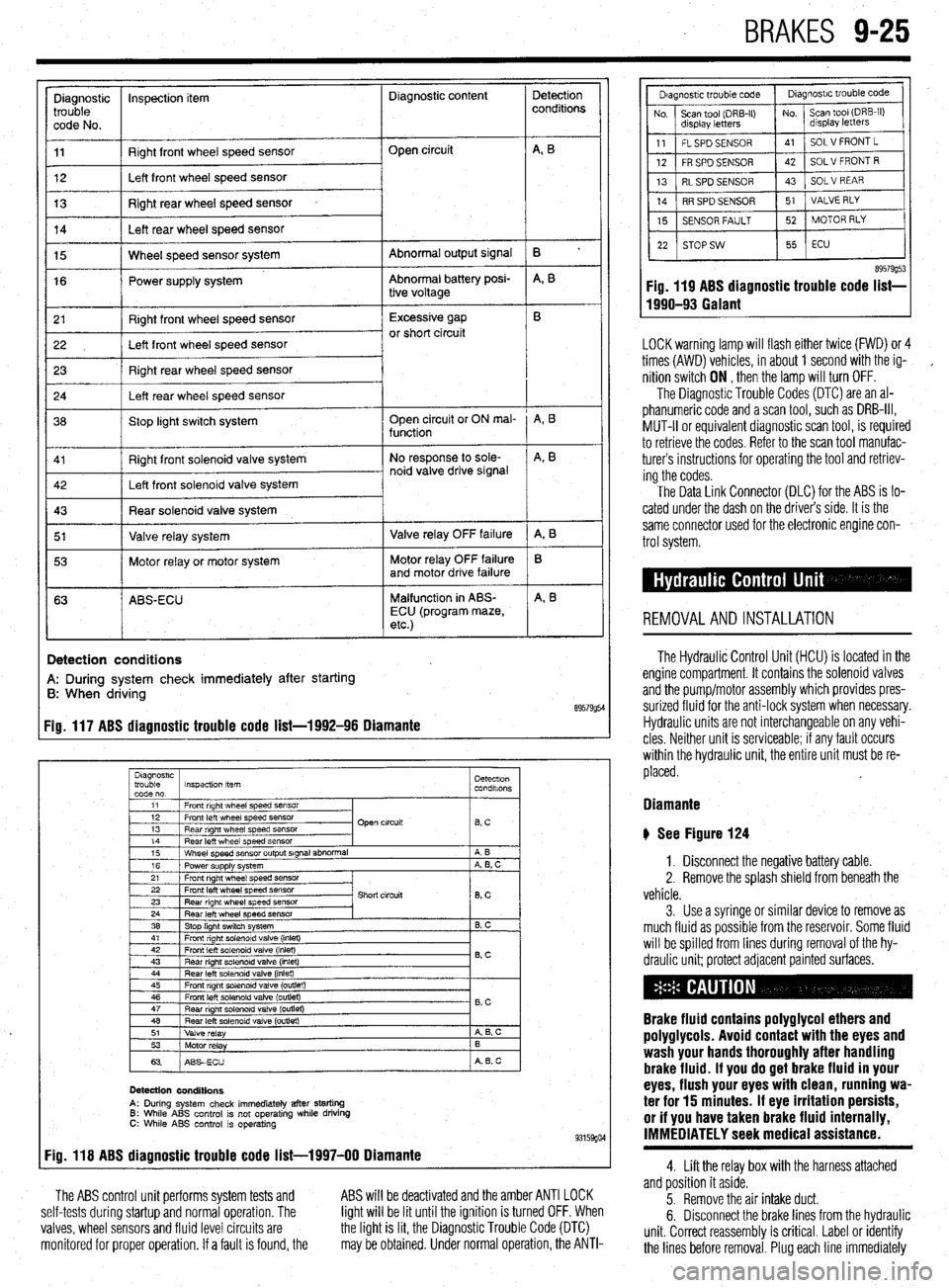
Diagnostic inspection item Diagnostic content
trouble
code No.
11 Right front wheel speed sensor
12 Left front wheel speed sensor Open circuit
13 Right rear wheel speed sensor
14 Left rear wheel speed sensor
Abnormal output signal
Abnormal battery posi-
tive voltage 15 Wheel speed sensor system
16 Power supply system
r 21
I Right front wheel speed sensor 1 Excessive gap
22 I Left front wheel speed sensor or short circuit
23 Right rear wheel speed sensor
24 Left rear wheel speed sensor
36 Stop light switch system Open circuit or ON mal-
function
Right front solenoid valve system
I 5’ I Valve relay system 1 Valve relay OFF failure
I 53 1 Motor relay or motor system Motor relay OFF failure
and motor drive failure
63 ABS-ECU Malfunction in ABS-
ECU (program maze,
etc.)
I
!
Detection
conditions
B ’
A, B
A, B
A, B
A, 8
B
A, B
Detection conditions
A: During system check immediately after starting
B: When driving
89579954 Fig. 117 ABS diagnostic trouble code list-1992-96 Diamante
Diagnostrc
trouble Inspection item Detectron
code no. condalons
1
11 1 Front right wheel speed SensOr
I
I I
12 1 Front left wheel speed sensor
13 1 Rear right wheel speed sensor Open circuit
lBsC I
14
Rear left wheel speed sensor
15 Wheel speed sensor output signal abnormal
16 Power supply system
21 Front right wheel speed sensor A B
A, B, C
22 Front left wheel speed sensor
23 Rear right wheel speed sensor
24 Rear left wheel speed sensor
38 Stop light switch system Short circuit
8, c
B. C
41 1 Front right solenoid valve (inlet)
I I
42
Front left solenoid valve (inlet)
43 Rear right solenord valve (inlet) 0.c
44 Rear left solenoid valve (inlet)
45 Front right solenoid valve (outlet)
46 Front left solenoid valve (outlet)
47
Rear nght solenoid valve (outret) - B,C
48 Rear left solenoid valve (outlet)
51
Valve relay A 6, c
53
Motor relay B
63 ABSECU A B, c
Detection conditions
A: During system check immediately after starting 6: While ABS control is not operating while driving C: While ABS control is operating 93159go4 Fig. 118 ABS diagnostic trouble code list-1997-00 Diamante
The ABS control unit performs system tests and
self-tests during startup and normal operation. The
valves, wheel sensors and fluid level circuits are
monitored for proper operation. If a fault is found, the ABS will be deactivated and the amber ANTI LOCK
light will be lit until the ignition is turned OFF. When
the light is lit, the Diagnostic Trouble Code (DTC)
may be obtained. Under normal operation, the ANTI-
89579g53 Fig. 119 ABS diagnostic trouble code list-
1990-93 Galant
LOCK warning lamp will flash either twice (FWD) or 4
times (AWD) vehicles, in about 1 second with the ig-
,
nition switch ON , then the lamp will turn OFF.
The Diagnostic Trouble Codes (DTC) are an al-
phanumeric code and a scan tool, such as DRB-III,
MUT-II or equivalent diagnostic scan tool, is required
to retrieve the codes. Refer to the scan tool manufac-
turers instructions for operating the tool and retriev-
ing the codes.
The Data Link Connector (DLC) for the ABS is lo-
cated under the dash on the driver’s side. It is the
same connector used for the electronic engine con-
trol system.
REMOVALANDINSTALLATION
The Hydraulic Control Unit (HCU) is located in the
engine compartment. It contains the solenoid valves
and the pump/motor assembly which provides pres-
surized fluid for the anti-lock system when necessary.
Hydraulic units are not interchangeable on any vehi-
cles Neither unit is serviceable; if any fault occurs
within the hydraulic unit, the entire unit must be re-
placed.
Diamante
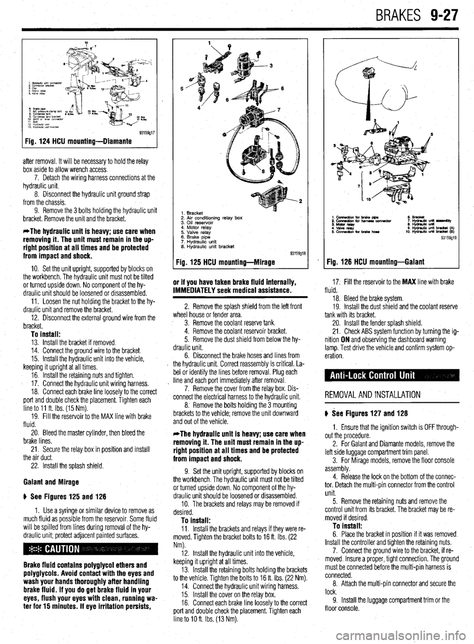
b See Figure 124
1. Disconnect the negative battery cable.
2. Remove the splash shield from beneath the
vehicle.
3. Use a syringe or similar device to remove as
much fluid as possible from the reservoir. Some fluid
will be spilled from lines during removal of the hy-
draulic unit; protect adjacent painted surfaces.
Brake fluid contains polyglycol ethers and
poly9lycols. Avoid contact with the eyes and
wash your hands thoroughly after handling
brake fluid. If you do 9et brake fluid in your
eyes, flush your eyes with clean, running wa-
ter for 15 minutes. If eye irritation persists,
or if you have taken brake fluid internally,
IMMEDIATELY seek medical assistance.
4. Lift the relay box with the harness attached
and position it aside.
5. Remove the air intake duct.
6. Disconnect the brake lines from the hydraulic
unit. Correct reassembly is critical. Label or identify
the lines before removal. Plug each line immediately
Page 363 of 408
BRAKES 9-27
93159g17
Fig. 124 HCU mounting-Diamante
after removal. It will be necessary to hold the relay
box aside to allow wrench access.
7. Detach the wiring harness connections at the
hydraulic unit.
8. Disconnect the hydraulic unit ground strap
from the chassis.
9. Remove the 3 bolts holding the hydraulic unit
bracket. Remove the unit and the bracket.
*The hydraulic unit is heavy; use care when
removing it. The unit must remain in the up-
right position at all times and be protected
from impact and shock.
IO. Set the unit upright, supported by blocks on
the workbench. The hydraulic unit must not be tilted
or turned upside down. No component of the hy-
draulic unit should be loosened or disassembled.
11. Loosen the nut holding the bracket to the hy-
draulic unit and remove the bracket.
12. Disconnect the external ground wire from the
bracket.
To install: 13. Install the bracket if removed.
14. Connect the ground wire to the bracket.
15. Install the hydraulic unit into the vehicle,
keeping it upright at all times.
16. Install the retaining nuts and tighten.
17. Connect the hydraulic unit wiring harness.
18. Connect each brake line loosely to the correct
port and double check the placement. Tighten each
line to 11 ft. Ibs. (15 Nm).
19. Fill the reservoir to the MAX line with brake
fluid.
20. Bleed the master cylinder, then bleed the
brake lines.
21. Secure the relay box in position and install
the air duct.
22. Install the splash shield.
Galant and Mirage
ti See Figures 125 and 126
1. Use a syringe or similar device to remove as
much fluid as possible from the reservoir. Some fluid
will be spilled from lines during removal of the hy-
draulic unit; protect adjacent painted surfaces.
Brake fluid contains polyglycol ethers and
polyglycols. Avoid contact with the eyes and
wash your hands thoroughly after handling
brake fluid. If you do get brake fluid in your
eyes, flush your eyes with clean, running wa-
ter for 15 minutes. If eye irritation persists,
1. Bracket
2. Air conditioning relay box
3. Oil reservoir
4. Motor relay
5. Valve relay
6. Brake pipe
7. Hydraulic unit
8. Hydraulic unit bracket
Fig. 125 HCU mounting-Mirage
or if you have taken brake fluid internally,
17. Fill the reservoir to the MAX line with brake IMMEDIATELY seek medical assistance. fluid.
2. Remove the splash shield from the left front
wheel house or fender area.
3. Remove the coolant reserve tank.
4. Remove the coolant reservoir bracket.
5. Remove the dust shield from below the hy-
draulic unit.
6. Disconnect the
brake hoses and lines from
the hydraulic unit. Correct reassembly is critical. La-
bel or identify the lines before removal. Plug each
line and each port immediately after removal.
7. Remove the cover from the relay box. Dis-
connect the electrical harness to the hydraulic unit.
8. Remove the bolts holding the 3 mounting
brackets to the vehicle; remove the unit downward
and out of the vehicle. 18. Bleed the brake system.
19. Install the dust shield and the coolant reserve
tank with its bracket.
20. Install the fender splash shield.
21. Check ABS system function by turning the ig-
nition ON and observing the dashboard warning
lamp. Test drive the vehicle and confirm system op-
eration.
REMOVALANDINSTALLATION
) See Figures 127 and 128
*The hydraulic unit is heavy; use care when
removing it. The unit must remain in the up-
right position at all times and be protected
from impact and shock.
9. Set the unit upright, supported by blocks on
the workbench. The hydraulic unit must not be tilted
or turned upside down. No component of the hy-
draulic unit should be loosened or disassembled.
10. The brackets and relays may be removed if
desired.
To install: 11. Install the brackets and relays if they were re-
moved. Tighten the bracket bolts to 16 ft. Ibs. (22
Nm). 1. Ensure that the ignition switch is OFF through-
out the procedure.
2. For Galant and Diamante models, remove the
left side luggage compartment trim panel.
3. For Mirage models, remove the floor console
assembly.
4. Release the lock on the bottom of the connec-
tor. Detach the multi-pin connector from the control
unit.
12. Install the hydraulic unit into the vehicle,
keeping it upright at all times.
13. Install the retaining bolts holding the brackets
to the vehicle. Tighten the bolts to 16 ft. Ibs. (22 Nm).
14. Connect the hydraulic unit wiring harness.
15. Install the cover on the relay box.
16. Connect each brake line loosely to the correct
port and double check the placement. Tighten each
line to IO ft. Ibs. (13 Nm). 5. Remove the retaining nuts and remove the
control unit from its bracket. The bracket may be re-
moved if desired. To install: 6. Place the bracket in position if it was removed.
Install the controller and tighten the retaining nuts.
7. Connect the ground wire to the bracket, if re-
moved. Insure a proper, tight connection. The ground
must be connected before the multi-pin harness is
connected.
8. Attach the multi-pin connector and secure the
lock.
9. Install the luggage compartment trim or the
floor console.
Fig. 126 HCU mounting-Galant
Page 376 of 408
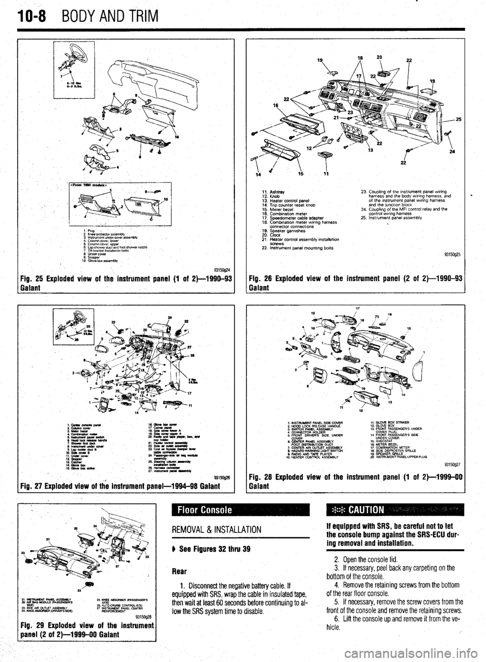
IO-8 BODYANDTRIM
cFroni 1990 ma&Is>
1 Plug
2 Knee pr&ctor assembb
3 lnsuumen~ under covet assembly
4. Column lxwer. lower :
5. Column cover upper
6 Lap shower duct and foot shcwai nozzle
7 Ttlt bracket installalm bolts
0 Undercover
9. stopper
10 Glove box assembly
93150@4 Fig. 25 Exploded view of the instrument panel (1 of 2)-1990-93 Fig. 26 Exploded view of the instrument panel (2 of 2)-1990-93
Galant Galant
1.CUllUCU+RC&pllU 16. Gbve bm eewr
i: iiiikz!!T 17. cucw gmnl
4. Cfnnbinuion meta 19. qds cww bww A
5 ‘~fiJzg%L L: ,“zr&, beat. md
21 L% sssemuy
8lmwmemu&cowr 236&1ou(W~
S.LapOdrduQB
10. slds cw4# B 23 ~u,~e-
11. LIdsI corn
::: s%ZZ
14. Gbw bx / ;:+q-=:-
kmasa
IS. Gkw ba SIiikw 2&HWSSCCl!ZL
2rtnsmlmuapr*lrvrnbly
@ma
Fig. 27 Exploded view of the instrument panel-1994-98 Galant
1;. p;;w
13: Heater control panel
14. Trip counter reset knob
15. Meter bezel
16. Combination meter
17. Speedometer cable adapter
18. Combrnatron meter wiring harness
connector connecttons
19. Speaker garnrshes
20. Clock 23. Coupling of the Instrument panel wiring
harness and the body wiring harness, and
of the Instrument panel wrring harness
and the junctlon block
24. Coupling of the MFI control relay and the
control wiring harness
25. Instrument panel assembly
21. Heater control assembly installation
9C?WS 22. Instrument panel mounting bolts
93150925
1. INSTRUMENT PANEL SIDE COVER
2. HOOD LOCK RELEASE HANDLE
3. SWITCH PANEL ASSEMBLY
4 CONNECTOR H+DER
5. ER DRIVERS SIDE UNDER
6. CENTER PANEL ASSEMBLY
FOOT MSTRISUTION DUCT
7. CENTER AIR OUTLET ASSEMBLY
8. HAZARO WARNING LIGHT SWfTCti
9. RADIO AN0 TAPE PLAYER
10. H!ZATER CONTROL ASSEMBLY 1,. GLOV2 BOX STRIKER
12. GLOVE SOX
13 FRONT PASSENGER’S UNOER
COVER PLUG
14. FRONT PASSENGER’S SIDE
UNDER COVER
15. RHEOSTAT
16. METER BEZEL
17. COMBINATION METER
18. SIDE DEFROSTER GRILLE
19 SPEAKER GRILLE
mo. INSTRUMENT PANEL UPPER PLUG
93159927
Fig. 28 Exploded view of the instrument panel (1 of 2)-1999-00
Galant
~~~~~~~~~
Fig. 29 Exploded view of the instrument
REMOVAL &INSTALLATION
) See Figures 32 thru 39 If equipped with SRS, be careful not to let
the console bump against the SRS-ECU dur-
ing removal and installation.
Rear 2. Open the console lid. 3. If necessary, peel back any carpeting on the
bottom of the console.
1. Disconnect the negative battery cable. If
equipped with SRS, wrap the cable in insulated tape,
then wait at least 60 seconds before continuing to al-
low the SRS system time to disable.
4. Remove the retaining screws from the bottom
of the rear floor console.
5. If necessary, remove the screw covers from the
front of the console and remove the retaining screws.
6. Lift the console up and remove it from the ve-
hicle.
rb
Page 383 of 408
TROUBLESHOOTING INDEX 11-2
SECTION 1: ENGINE 11-2
SECTION 2: DRIVE TRAIN
11-3
SECTION 3:BRAKESYSTEM 11-3
SECTION 4:WHEELS,TIRES, STEERING,
AND SUSPENSION II-4
SECTION 5: ELECTRICAL
ACCESSORIES II-4
SECTION 6:lNSTRUMENTSAND
GAUGES II-5
SECTION 7:CLlMATE CONTROL II-5
DIAGNOSTIC PROCEDURES II-6
SECTION 1: ENGINE II-6
ENGINE STARTING PROBLEMS II-6
ENGINE RUNNING CONDITIONS II-7
ENGINE NOISES,ODORSAND
VIBRATIONS II-8
ENGINE ELECTRICALSYSTEM 11-8
ENGINE COOLING SYSTEM II-8
ENGINE EXHAUSTSYSTEM II-9
SECTION 2: DRIVE TRAIN
II-9
AUTOMATIC TRANSMISSION II-9
MANUALTRANSMISSION II-10
CLUTCH II-10
DIFFERENTIAL AND FINAL
DRIVE II-10
TRANSFER ASSEMBLY II-10
DRIVESHAFT II-10
AXLES II-II
OTHER DRIVE TRAIN
CONDITIONS II-II
SECTION 3:BRAKE SYSTEM II-II
BRAKESYSTEM
TROUBLESHOOTING II-II
SECTION 4:WHEELS, TIRES, STEERING
AND SUSPENSION II-12
WHEELSAND WHEEL
BEARINGS II-12
TIRES II-12
STEERING II-12
SUSPENSION II-12
DRIVING NOISES AND
VIBRATIONS II-13
SECTION 5:ELECTRlCAL
ACCESSORIES II-13 -
HEADLIGHTS II-13
TAIL, RUNNING AND SIDE MARKER
LIGHTS II-13
INTERIOR LIGHTS II-14
BRAKE LIGHTS II-14
WARNING LIGHTS II-14
TURN SlGNALAND4-WAYHAZARD
LIGHTS II-15
WINDSHIELD WIPERS II-15
SECTION 6:lNSTRUMENTSAND
GAUGUES II-15
I
SPEEDOMETER(CABLE
OPERATED) II-15
SPEEDOMETER(ELECTRONICALLY
OPERATED) II-16
FUEL,TEMPERATUREAkJD OIL
PRESSURE GAUGES II-16 SECTION 7:CLlMATECON
AIR CONDITIONER ll-
HEATER II-16 TR(
-16 IL II-16
Page 387 of 408
.
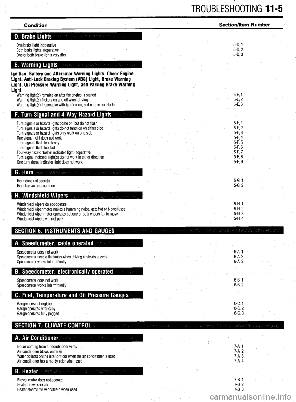
TROUBLESHOOTING II-5
Condition Section/Item Number
One brake light inoperative
Both brake lights inoperative
One or both brake lights very dim 5-D, 1
5-D, 2
5-D, 3
Ignition, Battery and Alternator Warning Lights, Check Engine
Light, Anti-Lock Braking System (ABS) Light, Brake Warning
Light, Oil Pressure Warning Light, and Parking Brake Warning
Light
Warning light(s) remains on after the engine is started
Warning light(s) flickers on and off when driving
Warning light(s) inoperative with ignition on, and engine not started 5-E, 1
5-E, 2
5-E, 3
Turn signals or hazard lights come on, but do not flash
Turn signals or hazard lights do not function on either side
Turn signals or hazard lights only work on one side
One signal light does not work
Turn signals flash too slowly
Turn signals flash too fast
Four-way hazard flasher indicator light inoperative
Turn signal indicator light(s) do not work in either direction
One turn signal indicator light does not work 5-F, 1
5-F, 2
5-F, 3
5-F, 4
5-F, 5
5-F, 6
5-F, 7
5-F, 8
5-F, 9
Horn does not operate
Horn has an unusual tone 5-G, 1
5-G, 2
Windshield wipers do not operate
Windshield wiper motor makes a humming noise, gets hot or blows fuses
Windshield wiper motor operates but one or both wipers fail to move
Windshield wipers will not park 5-H, 1
5-H, 2
5-H, 3
5-H, 4
Speedometer does not work
Speedometer needle fluctuates when driving at steady speeds
Speedometer works intermittently 6-A, 1
6-A, 2
6-A, 3
Speedometer does not work
Speedometer works intermittently 6-B, 1
6-B, 2
Gauge does not register 6-C 1
Gauge operates erratically 6-C 2
’
Gauge operates fully pegged 6-C 3
No air coming from air conditioner vents 7-A, 1
Air conditioner blows warm air ’ 7-A, 2
Water collects on the interior floor when the air conditioner is used
Air conditioner has a moldy odor when used 7-A, 3
7-A, 4
Blower motor does not operate
Heater blows cool air
Heater steams the windshield when used 7-B, 1
7-B, 2
7-B, 3
Page 390 of 408
11-8 TROUBLESHOOTING
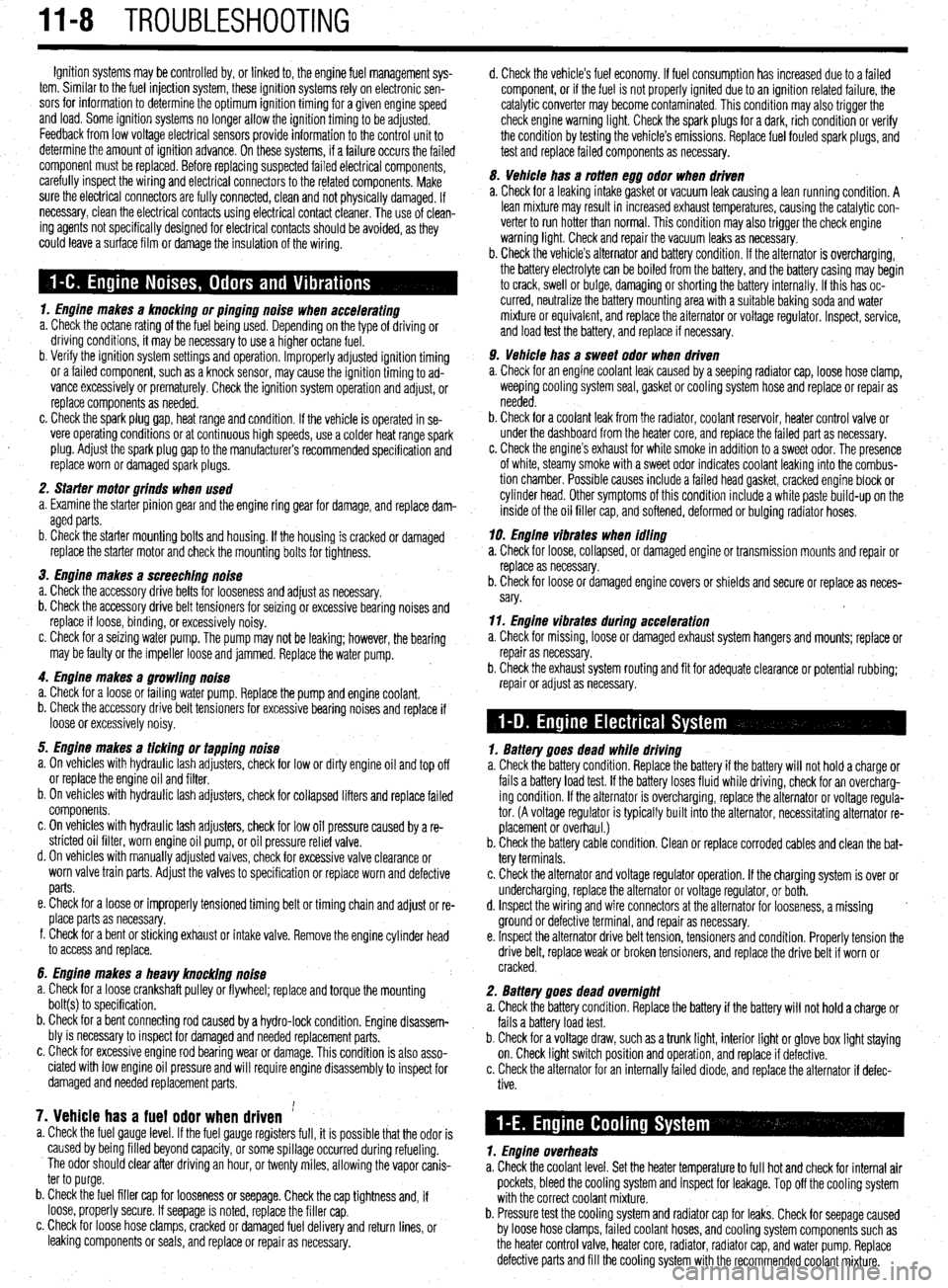
Ignition systems may be controlled by, or linked to, the engine fuel management sys-
tem. Similar to the fuel injection system, these ignition systems rely on electronic sen-
sors for information to determine the optimum ignition timing for a given engine speed
and load. Some ignition systems no longer allow the ignition timing to be adjusted.
Feedback from low voltage electrical sensors provide information to the control unit to
determine the amount of ignition advance. On these systems, if a failure occurs the failed
component must be replaced. Before replacing suspected failed electrical components,
carefully inspect the wiring and electrical connectors to the related components. Make
sure the electrical connectors are fully connected, clean and not physically damaged. If
necessary, clean the electrical contacts using electrical contact cleaner. The use of clean-
ing agents not specifically designed for electrical contacts should be avoided, as they
could leave a surface film or damage the insulation of the wiring.
1. Engine makes a knocking or pinging noise when accelerating
a. Check the octane rating of the fuel being used. Depending on the type of driving or
driving conditions, it may be necessary to use a higher octane fuel.
b. Verify the ignition system settings and operation. Improperly adjusted ignition timing
or a failed component, such as a knock sensor, may cause the ignition timing to ad-
vance excessively or prematurely. Check the ignition system operation and adjust, or
replace components as needed.
c. Check the spark plug gap, heat range and condition. If the vehicle is operated in se-
vere operating conditions or at continuous high speeds, use a colder heat range spark
plug. Adjust the spark plug gap to the manufacturer’s recommended specification and
replace worn or damaged spark plugs.
2. Sfarter motor grinds when used
a. Examine the starter pinion gear and the engine ring gear for damage, and replace dam-
aged parts.
b. Check the starter mounting bolts and housing. If the housing is cracked or damaged
replace the starter motor and check the mounting bolts for tightness.
3. Engine makes a screeching noise
a. Check the accessory drive belts for looseness and adjust as necessary.
b. Check the accessory drive belt tensioners for seizing or excessive bearing noises and
replace if loose, binding, or excessively noisy.
c. Check for a seizing water pump. The pump may not be leaking; however, the bearing
may be faulty or the impeller loose and jammed. Replace the water pump.
4. Engine makes a growling noise
a. Check for a loose or failing water pump. Replace the pump and engine coolant.
b. Check the accessory drive belt tensioners for excessive bearing noises and replace if
loose or excessively noisy.
5. Engine makes a ticking or tapping noise
a. On vehicles with hydraulic lash adjusters, check for low or dirty engine oil and top off
or replace the engine oil and filter.
b. On vehicles with hydraulic lash adjusters, check for collapsed lifters and replace failed
components.
c. On vehicles with hydraulic lash adjusters, check for low oil pressure caused by a re-
stricted oil filter, worn engine oil pump, or oil pressure relief valve.
d. On vehicles with manually adjusted valves, check for excessive valve clearance or
worn valve train parts. Adjust the valves to specification or replace worn and defective
parts.
e. Check for a loose or improperly tensioned timing belt or timing chain and adjust or re-
place parts as necessary.
f. Check for a bent or sticking exhaust or intake valve. Remove the engine cylinder head
to access and replace.
6. Engine makes a heavy knocking noise
a. Check for a loose crankshaft pulley or flywheel; replace and torque the mounting
bolt(s) to specification.
b. Check for a bent connecting rod caused by a hydro-lock condition. Engine disassem-
bly is necessary to inspect for damaged and needed replacement parts.
c. Check for excessive engine rod bearing wear or damage. This condition is also asso-
ciated with low engine oil pressure and will require engine disassembly to inspect for
damaged and needed replacement parts,
7. Vehicle has a fuel odor when driven ’ a. Check the fuel gauge level. If the fuel gauge registers full, it is possible that the odor is
caused by being filled beyond capacity, or some spillage occurred during refueling.
The odor should clear after driving an hour, or twenty miles, allowing the vapor canis-
ter to purge.
b. Check the fuel filler cap for looseness or seepage. Check the cap tightness and, if
loose, properly secure. If seepage is noted, replace the filler cap.
c. Check for loose hose clamps, cracked or damaged fuel delivery and return lines, or
leaking components or seals, and replace or repair as necessary. d. Check the vehicle’s fuel economy. If fuel consumption has increased due to a failed
component, or if the fuel is not properly ignited due to an ignition related failure, the
catalytic converter may become contaminated. This condition may also trigger the
check engine warning light. Check the spark plugs for a dark, rich condition or verify
the condition by testing the vehicle’s emissions. Replace fuel fouled spark plugs, and
test and replace failed components as necessary.
5. Vehicle has a rotten egg odor when driven
a. Check for a leaking intake gasket or vacuum leak causing a lean running condition. A
lean mixture may result in increased exhaust temperatures, causing the catalytic con-
verter to run hotter than normal. This condition may also trigger the check engine
warning light. Check and repair the vacuum leaks as necessary.
b. Check the vehicle’s alternator and battery condition. If the alternator is overcharging,
the battery electrolyte can be boiled from the battery, and the battery casing may begin
to crack, swell or bulge, damaging or shorting the battery internally. If this has oc-
curred, neutralize the battery mounting area with a suitable baking soda and water
mixture or equivalent, and replace the alternator or voltage regulator. Inspect, service,
and load test the battery, and replace if necessary.
9. Vehicle has a sweet odor when driven
a. Check for an engine coolant leak caused by a seeping radiator cap, loose hose clamp,
weeping cooling system seal, gasket or cooling system hose and replace or repair as
needed.
b. Check for a coolant leak from the radiator, coolant reservoir, heater control valve or
under the dashboard from the heater core, and replace the failed part as necessary.
c. Check the engine’s exhaust for white smoke in addition to a sweet odor. The presence
of white, steamy smoke with a sweet odor indicates coolant leaking into the combus-
tion chamber. Possible causes include a failed head gasket, cracked engine block or
cylinder head. Other symptoms of this condition include a white paste build-up on the
inside of the oil filler cap, and softened, deformed or bulging radiator hoses.
19. Engine vibraies when idling
a. Check for loose, collapsed, or damaged engine or transmission mounts and repair or
replace as necessary.
b. Check for loose or damaged engine covers or shields and secure or replace as neces-
sary.
11. Engine vibrates during acceleration
a. Check for missing, loose or damaged exhaust system hangers and mounts; replace or
repair as necessary.
b. Check the exhaust system routing and fit for adequate clearance or potential rubbing;
repair or adjust as necessary.
7. Battery goes dead while driving
a. Check the battery condition. Replace the battery if the battery will not hold a charge or
fails a battery load test. If the battery loses fluid while driving, check for an overcharg-
ing condition. If the alternator is overcharging, replace the alternator or voltage regula-
tor. (A voltage regulator is typically built into the alternator, necessitating alternator re-
placement or overhaul.)
b. Check the battery cable condition. Clean or replace corroded cables and clean the bat-
tery terminals.
c. Check the alternator and voltage regulator operation. If the charging system is over or
undercharging, replace the alternator or voltage regulator, or both.
d. Inspect the wiring and wire connectors at the alternator for looseness, a missing .
ground or defective terminal, and repair as necessary.
e. Inspect the alternator drive belt tension, tensioners and condition. Properly tension the
drive belt, replace weak or broken tensioners, and replace the drive belt if worn or
cracked.
2. Battery goes dead overnight
a. Check the battery condition. Replace the battery if the battery will not hold a charge or
fails a battery load test.
b. Check for a voltage draw, such as a trunk light, interior light or glove box light staying
on. Check light switch position and operation, and replace if defective.
c. Check the alternator for an internally failed diode, and replace the alternator if defec-
tive.
1. Engine overheats
a. Check the coolant level. Set the heater temperature to full hot and check for internal air
pockets, bleed the cooling system and inspect for leakage. Top off the cooling system
with the correct coolant mixture.
b. Pressure test the cooling system and radiator cap for leaks. Check for seepage caused
by loose hose clamps, failed coolant hoses, and cooling system components such as
the heater control valve, heater core, radiator, radiator cap, and water pump. Replace
defective parts and fill the cooling system with the recommended coolant mixture.