1900 MITSUBISHI DIAMANTE glove box
[x] Cancel search: glove boxPage 372 of 408
10-4 BODYANDTRIM
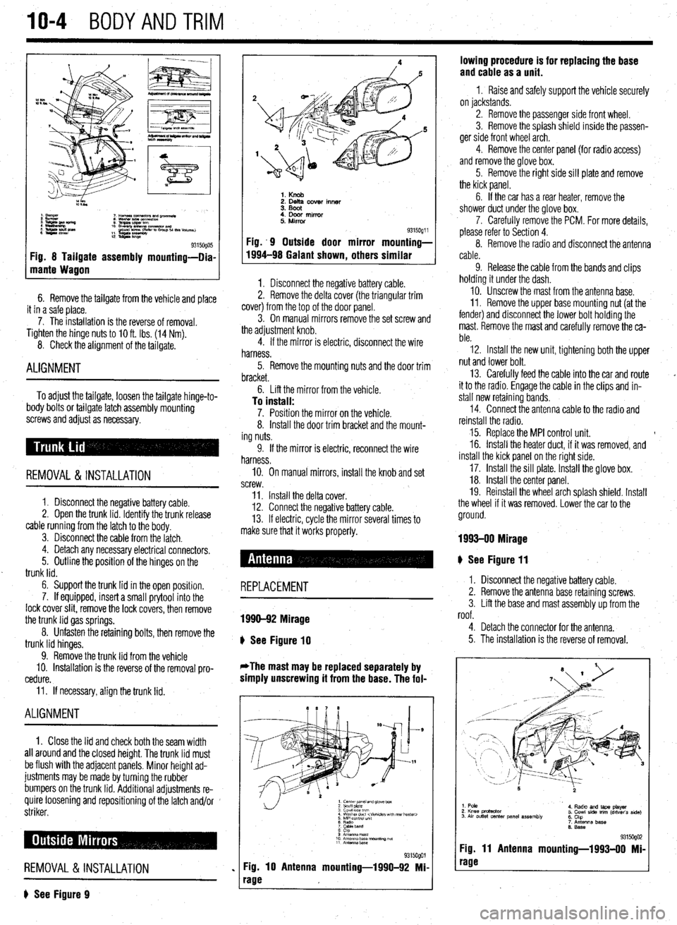
Fig. 8 Tailgate assembly mounting-Dia-
mante Wagon
6. Remove the tailgate from the vehicle and place
it in a safe place.
7. The installation is the reverse of removal.
Tighten the hinge
nuts to IO ft. Ibs. (14 Nm).
8. Check the alignment of the tailgate.
ALIGNMENT
To adjust the tailgate, loosen the tailgate hinge-to-
body bolts or tailgate latch assembly mounting
screws and adjust as necessary.
REMOVAL &INSTALLATION
1. Disconnect the negative battery cable.
2. Open the trunk lid. Identify the trunk release
cable running from the latch to the body.
3. Disconnect the cable from the latch.
4. Detach any necessary electrical connectors.
5. Outline the position of the hinges on the
trunk lid.
6. Support the trunk lid in the open position.
7. If equipped, insert a small prytool into the
lock cover slit, remove the lock covers, then remove
the trunk lid gas springs.
8. Unfasten the retaining bolts, then remove the
trunk lid hinges.
9. Remove the trunk lid from the vehicle
10. Installation is the reverse of the removal pro-
cedure.
11. If necessary, align the trunk lid.
ALIGNMENT
1. Close the lid and check both the seam width
all around and the closed height. The trunk lid must
be flush with the adjacent panels. Minor height ad-
justments may be made by turning the rubber
bumpers on the trunk lid. Additional adjustments re-
quire loosening and repositioning of the latch and/or
striker.
REMOVAL &INSTALLATION
? See Figure 9
1. Knob 2. Delta cover inner
3. Boot
4. Door mirror
5. Mirror
Fig. .9 Outside door mirror
1994-98 Galant shown
, others 9315oQ1 i mounting-
similar
1. Disconnect the negative battery cable.
2. Remove the delta cover (the triangular trim
cover) from the top of the door panel.
3. On manual mirrors remove the set screw and
the adjustment knob.
4. If the mirror is electric, disconnect the wire
harness.
5. Remove the mounting nuts and the door trim
bracket.
6. Lift the mirror from the vehicle.
To install: 7. Position the mirror on the vehicle.
8. Install the door trim bracket and the mount-
ing nuts.
9. If the mirror is electric, reconnect the wire
harness.
IO. On manual mirrors, install the knob and set
screw.
11. Install the delta cover.
12. Connect the negative battery cable.
13. If electric, cycle the mirror several times to
make sure that it works properly.
# See Figure 11
REPLACEMENT
1990-92 Mirage
b
See Figure 10
*The mast may be replaced separately by
simply unscrewing it from the base. The fol-
1. center panel and glove box
2 scuff plate
3 cowl 51ae wm
4 Washer duct
7 CaMeband
8 cap
9 Anrsnna mast
10 Antenna base “ourmng ““f
11 Antennz.base
%i%Qol
Fig. 10 Antenna mounting-1990-92 Mi-
rage lowing procedure is for replacing the base
and cable as a unit.
1 I Raise and safely support the vehicle securely
on jackstands.
2. Remove the passenger side front wheel.
3. Remove the splash shield inside the passen-
ger side front wheel arch.
4. Remove the center panel {for radio access)
and remove the glove box.
5. Remove the right side sill plate and remove
the kick panel.
6. If the car has a rear heater, remove the
shower duct under the glove box.
7. Carefully remove the PCM. For more details,
please refer to Section 4.
8. Remove the radio and disconnect the antenna
cable.
9. Release the cable from the bands and clips
holding it under the dash.
10. Unscrew the mast from the antenna base.
II. Remove the upper base mounting nut (at the
fender) and disconnect the lower bolt holding the
mast. Remove the mast and carefully remove the ca-
ble.
12. Install the new unit, tightening both the upper
nut and lower bolt.
13. Carefully feed the cable into the car and route
it to the radio. Engage the cable in the clips and in-
stall new retaining bands.
14. Connect the antenna cable to the radio and
reinstall the radio.
15. Replace the MPI control unit. t
16. Install the heater duct, if it was removed, and
install the kick panel on the right side.
17. Install the sill plate. Install the glove box.
18. Install the center panel.
19. Reinstall the wheel arch splash shield. Install
the wheel if it was removed. Lower the car to the
ground.
1993-00 Mirage
I. Disconnect the negative battery cable.
2. Remove the antenna base retaining screws.
3. Lift the base and mast assembly up from the
roof.
4. Detach the connector for the antenna.
5. The installation is the reverse of removal.
1. Pole
2. Knee protactor
3. Air outlet center panel assembly 4. Radto and laps player
5. Cowl side trim (driver’s side)
6. Chp
7. Antenna base
6. Base
931 !iogo2 Fig. 11 Antenna mounting-1993-00 Mi-
rage
Page 375 of 408
BODYANDTRIM IO-7
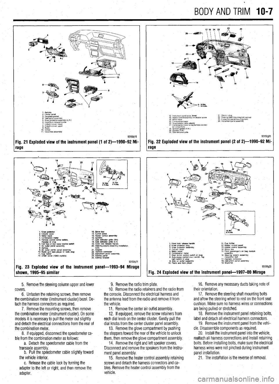
1. Ashtray
2 cenrer DaneI
3. Sunglass pocket
4 Side panel assembly
5 Knee protector assembly (L
6 Hood lock release handle
7 Column cover. lower
8 Column cover. upper
9 Radio
10 Striker
11. Glove box assembly
Fig. 21 Exploded view of the instrument panel (1 of 2)-1990-92 Mi-
rage
1. Knee pmtector
2. Column cover
3. Meter bezel
4. Combination meter
5. Remote control mirror switch.
rhsostat or plug
6. Coin box or rear wper washer switch
7. Aw outlet panel assembly
6. Ashtray
0. Air outlet center panel assembly
10. Radio and tape player or radio plug
11. Cup holder
12. Under COW (1993 models) 14. Comer panel
15. Heater control assembly %.
16. Speaker
17. Side defroster grille (RH)
16. Side defroster grille (LH)
19. Hood lock release handle
20. Ee$ng column assembly mstallation
21. Adapter
22 Harness oonnector
23. Instrument panel assembly
24. Ashtray panel
25. Ashtray bracket
9315og21 Fig. 23 Exploded view of the instrument panel-1993-94 Mirage
shown, 1995-95 similar
5. Remove the steering column upper and lower
covers.
6. Unfasten the retaining screws, then remove
the combination meter (instrument cluster) bezel. De-
tach the harness connectors as required.
7. Remove the mounting screws, then remove
the combination meter (instrument cluster). On some
models it is necessary to pull the meter out slightly
and detach the electrical connections from the rear of
the combination meter.
8. If equipped, disconnect the speedometer ca-
ble from the combination meter as follows:
a. Detach the speedometer cable from the
transaxle assembly.
b. Pull the speedometer cable slightly toward
the vehicle interior.
c. Release the cable lock by turning the
adapter to the left or right, and then remove the
adapter.
18
S-14Nm
7-lOh.lbs.
12 ln~v~rnent panel cover. lower
13 Hearer control assembly w,tallatlon screw
14 Meter bezel
15 Combination meter
16 Speedometer cable adapter
17 Comblnawn meterwr~ng harness connec-
. to1 co”“ectlo”s
16 Speaker amlsh (R H )
19 Speaker RHI e
20 S\de defroster grllla 21 Clock 01 plug
22 Steering shaft mount,ng bolt and nut
23 Ins!rument panel mounting bolts
24 Instrument panel assembly
9315og20 Fig. 22 Exploded view of the instrument panel (2 of 2)-1990-92 Mi-
rage
Fig. 24
1. Hood lock release handle
2. Knee protactor plug
3. Knee protector assembly
4 Column cover
5. Meter bezel
6. Combination meter
7. Door mrror control swich or plug
6. Auto-CNISO control mam swtch. fog
hght swtch M plug
0. Stde av outlet assembly
10 Radio and tape player 11. Cup holder
12. Heater control panel
13. Heater control assembly
14. Glove box
15 Front passenger’s 81, bag module
assembly
16. Steerq column assembly
lnstallatlon bon
17. Harness connector
16. Instrument panel assembly
19 Grommet
Exploded view of the instrument panel-l 997-00 Mirage
9. Remove the radio trim plate.
IO. Remove the radio retainers and the radio from
the console. Disconnect the electrical harness and
the antenna lead from the radio and remove it from
the vehicle.
11. Remove the center air outlet assembly.
12. If equipped, remove the screw retainers from
each dial knob on the center cluster. Gently pull the
dial knobs from the center cluster panel assembly.
13. Remove the glove compartment by pushing
the stoppers toward the rear of the vehicle to unlock
them, then remove the glove compartment assembly.
14. Remove the right and left speaker covers.
Disconnect and remove the speakers from the instru-
ment panel assembly.
15. Remove the heater control assembly retaining
screws and detach the harness connectors and ca-
bles. Remove the heater control assembly from the
vehicle. , 16. Remove any necessary ducts taking note of
their orientation,
17. Remove the steering shaft mounting bolts
and allow the steering wheel to rest on the front seat
cushion, Make sure no harness wires or connections
are being pulled or stretched.
18. Remove the instrument panel retaining bolts,
label and detach all electrical harness connectors.
19. Remove the instrument panel from the vehi-
cle. Disassemble components as required.
20. Install the instrument panel into the vehicle,
reattach all harness connections and install retaining
bolts. Before installing bolts, make sure the electrical
harness wires were not pinched during instrument
panel installation.
21. The installation is the reverse of removal.
Page 376 of 408
IO-8 BODYANDTRIM
cFroni 1990 ma&Is>
1 Plug
2 Knee pr&ctor assembb
3 lnsuumen~ under covet assembly
4. Column lxwer. lower :
5. Column cover upper
6 Lap shower duct and foot shcwai nozzle
7 Ttlt bracket installalm bolts
0 Undercover
9. stopper
10 Glove box assembly
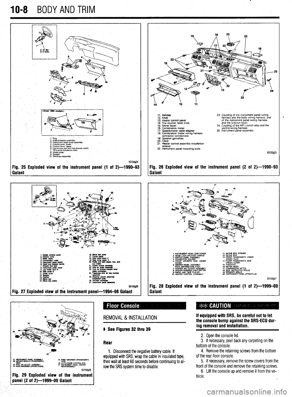
93150@4 Fig. 25 Exploded view of the instrument panel (1 of 2)-1990-93 Fig. 26 Exploded view of the instrument panel (2 of 2)-1990-93
Galant Galant
1.CUllUCU+RC&pllU 16. Gbve bm eewr
i: iiiikz!!T 17. cucw gmnl
4. Cfnnbinuion meta 19. qds cww bww A
5 ‘~fiJzg%L L: ,“zr&, beat. md
21 L% sssemuy
8lmwmemu&cowr 236&1ou(W~
S.LapOdrduQB
10. slds cw4# B 23 ~u,~e-
11. LIdsI corn
::: s%ZZ
14. Gbw bx / ;:+q-=:-
kmasa
IS. Gkw ba SIiikw 2&HWSSCCl!ZL
2rtnsmlmuapr*lrvrnbly
@ma
Fig. 27 Exploded view of the instrument panel-1994-98 Galant
1;. p;;w
13: Heater control panel
14. Trip counter reset knob
15. Meter bezel
16. Combination meter
17. Speedometer cable adapter
18. Combrnatron meter wiring harness
connector connecttons
19. Speaker garnrshes
20. Clock 23. Coupling of the Instrument panel wiring
harness and the body wiring harness, and
of the Instrument panel wrring harness
and the junctlon block
24. Coupling of the MFI control relay and the
control wiring harness
25. Instrument panel assembly
21. Heater control assembly installation
9C?WS 22. Instrument panel mounting bolts
93150925
1. INSTRUMENT PANEL SIDE COVER
2. HOOD LOCK RELEASE HANDLE
3. SWITCH PANEL ASSEMBLY
4 CONNECTOR H+DER
5. ER DRIVERS SIDE UNDER
6. CENTER PANEL ASSEMBLY
FOOT MSTRISUTION DUCT
7. CENTER AIR OUTLET ASSEMBLY
8. HAZARO WARNING LIGHT SWfTCti
9. RADIO AN0 TAPE PLAYER
10. H!ZATER CONTROL ASSEMBLY 1,. GLOV2 BOX STRIKER
12. GLOVE SOX
13 FRONT PASSENGER’S UNOER
COVER PLUG
14. FRONT PASSENGER’S SIDE
UNDER COVER
15. RHEOSTAT
16. METER BEZEL
17. COMBINATION METER
18. SIDE DEFROSTER GRILLE
19 SPEAKER GRILLE
mo. INSTRUMENT PANEL UPPER PLUG
93159927
Fig. 28 Exploded view of the instrument panel (1 of 2)-1999-00
Galant
~~~~~~~~~
Fig. 29 Exploded view of the instrument
REMOVAL &INSTALLATION
) See Figures 32 thru 39 If equipped with SRS, be careful not to let
the console bump against the SRS-ECU dur-
ing removal and installation.
Rear 2. Open the console lid. 3. If necessary, peel back any carpeting on the
bottom of the console.
1. Disconnect the negative battery cable. If
equipped with SRS, wrap the cable in insulated tape,
then wait at least 60 seconds before continuing to al-
low the SRS system time to disable.
4. Remove the retaining screws from the bottom
of the rear floor console.
5. If necessary, remove the screw covers from the
front of the console and remove the retaining screws.
6. Lift the console up and remove it from the ve-
hicle.
rb
Page 377 of 408
c BODYANDTRi'l IO-9
:: k% protector assembly
3. Knee protector support bracket
4. Column cover
5 Glove box striker
6 Glove box and glove box outer case
7 Under cover mstallatmn screw
8. Audio panel
9 Radio and tape player
10 Heater control panel
assembly 11 Cup holder
12. Speaker
13 Meter bezel
14 Combination meter
15 Speeoometer cable adapter
16 %&rrng column assembly rnstallatioh
17 Harness connector
18. Glove box kght swatch
19. Instrument panel assembly
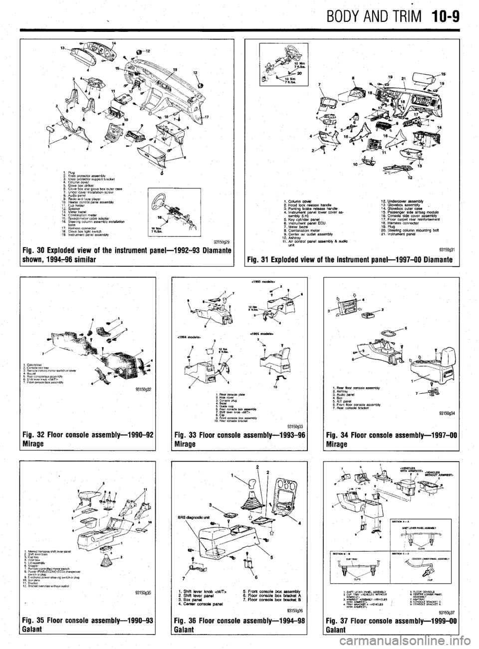
9315og29 Fig. 30 Exploded view of the instrument panel-1992-93 Diamante
shown, 1994796 similar
I Cam holder
2 Console box tray
3 Remote control mrror swatch drcover
1 Berrel
3 Rear cms~ie box assembly
3 Shift lever knob 4vitT>
7 Front eonsale box assembly
Fig. 32 Floor console assembly-1990-92
Yg. 33 Floor console assembly-1993-96
Nlirage
Mirage
1 Manual tmnsaxle shrft lever panel 2 Shrft lever boat 3. cup tray 4 lnnerbdx
6 Lrd assembly
6 Stopper 7 Remote cO”trOned nl,rrorSwl,Ch 8 PowerlFVWECONO (EC01 changeover
12 Bracket Wvcles wrthout addlo)
Fig. 35 Floor console assembly-l 990-93
Galant
4’
2
ia
9315og31 Fig. 31
Exploded view of the instrument
panel-l 997-00 Diamante
1. Column cover
2. Hood lock release handle
3. Parking brake release handle
4. Instrument anal lower cover as-
sembly (LH
P 5. Key cylinder panel
6. instrument panel ECU
7. Meter bezel
0. Combination meter 9. Center air outlet assembly
10. Ashtray
11. Air control panel assembly 8 audio
unit 12. Undercover assembly
13. Glovebox assembly
14. Glovebox outer case
15. Passenger side airbag module
16. Console side cover assemblv
17. Flow carpet rear rainforcem&t
18. Harness connector
19. Plug
20. Steering column mountlng bolt
21. Instrument panel
6 Rear cmsole box es%mbly
7
Shrff lever knob
6. CtQ 9 Front console box assembfk
10. Rear console bracket 9315og33
7 6
1. Shii lever knob &ATT:.
2. Shi lever panel
3. Box panel
4. Center console panel 5. Front console box assembly
6. Floor console box bracket A
7. floar console box bradret B
Fig. 36 Floor console assembly-1994-98
Galant
1. Rear floor console assembly
2. Ashtray
6. Front floor console assembly
7 Rear console bracket
Fig. 34 Floor console assembly-1997-00
Mirage
Fig. 37 Floor console assembly-l 999-00
Galant
Page 390 of 408
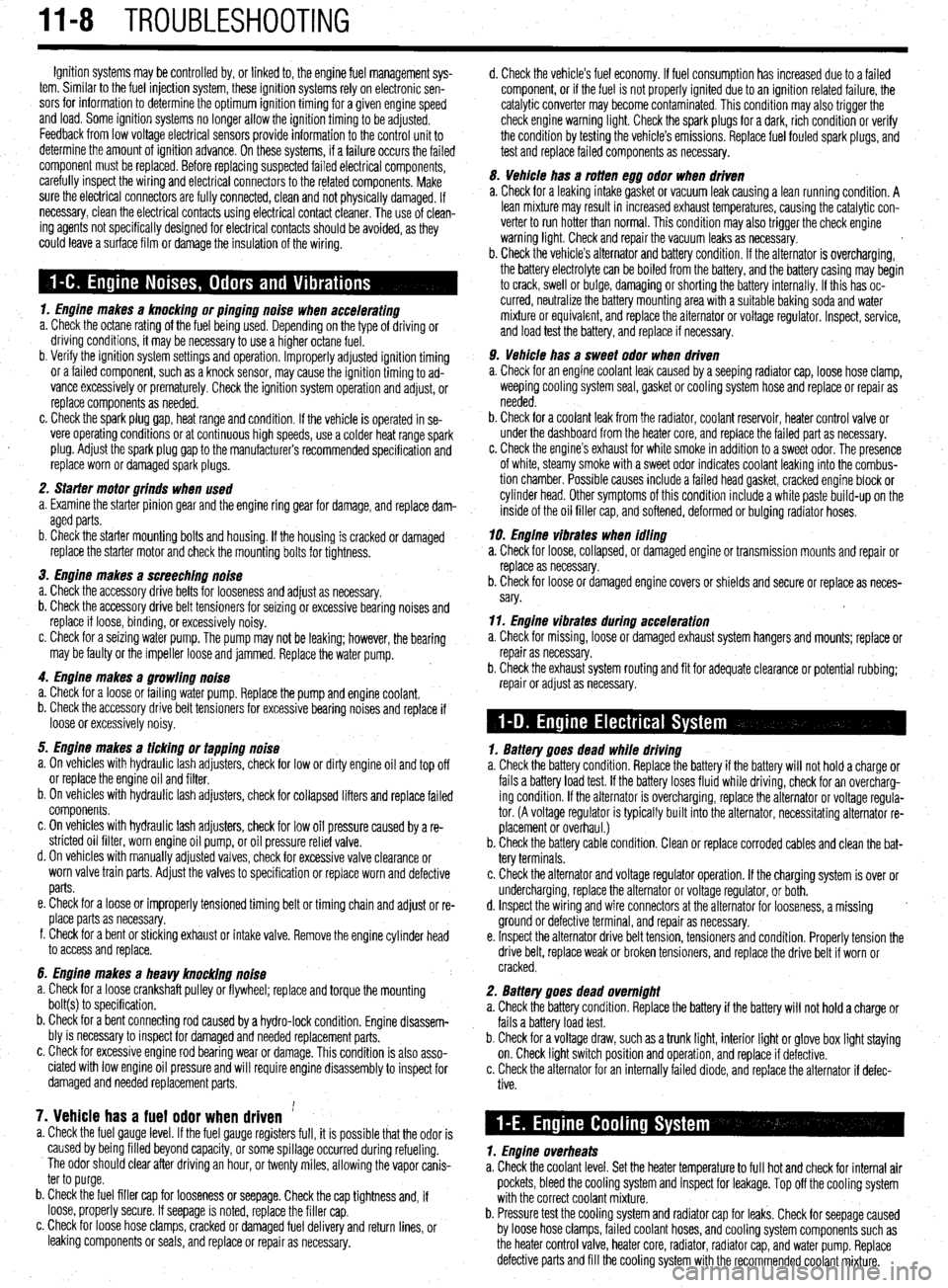
11-8 TROUBLESHOOTING
Ignition systems may be controlled by, or linked to, the engine fuel management sys-
tem. Similar to the fuel injection system, these ignition systems rely on electronic sen-
sors for information to determine the optimum ignition timing for a given engine speed
and load. Some ignition systems no longer allow the ignition timing to be adjusted.
Feedback from low voltage electrical sensors provide information to the control unit to
determine the amount of ignition advance. On these systems, if a failure occurs the failed
component must be replaced. Before replacing suspected failed electrical components,
carefully inspect the wiring and electrical connectors to the related components. Make
sure the electrical connectors are fully connected, clean and not physically damaged. If
necessary, clean the electrical contacts using electrical contact cleaner. The use of clean-
ing agents not specifically designed for electrical contacts should be avoided, as they
could leave a surface film or damage the insulation of the wiring.
1. Engine makes a knocking or pinging noise when accelerating
a. Check the octane rating of the fuel being used. Depending on the type of driving or
driving conditions, it may be necessary to use a higher octane fuel.
b. Verify the ignition system settings and operation. Improperly adjusted ignition timing
or a failed component, such as a knock sensor, may cause the ignition timing to ad-
vance excessively or prematurely. Check the ignition system operation and adjust, or
replace components as needed.
c. Check the spark plug gap, heat range and condition. If the vehicle is operated in se-
vere operating conditions or at continuous high speeds, use a colder heat range spark
plug. Adjust the spark plug gap to the manufacturer’s recommended specification and
replace worn or damaged spark plugs.
2. Sfarter motor grinds when used
a. Examine the starter pinion gear and the engine ring gear for damage, and replace dam-
aged parts.
b. Check the starter mounting bolts and housing. If the housing is cracked or damaged
replace the starter motor and check the mounting bolts for tightness.
3. Engine makes a screeching noise
a. Check the accessory drive belts for looseness and adjust as necessary.
b. Check the accessory drive belt tensioners for seizing or excessive bearing noises and
replace if loose, binding, or excessively noisy.
c. Check for a seizing water pump. The pump may not be leaking; however, the bearing
may be faulty or the impeller loose and jammed. Replace the water pump.
4. Engine makes a growling noise
a. Check for a loose or failing water pump. Replace the pump and engine coolant.
b. Check the accessory drive belt tensioners for excessive bearing noises and replace if
loose or excessively noisy.
5. Engine makes a ticking or tapping noise
a. On vehicles with hydraulic lash adjusters, check for low or dirty engine oil and top off
or replace the engine oil and filter.
b. On vehicles with hydraulic lash adjusters, check for collapsed lifters and replace failed
components.
c. On vehicles with hydraulic lash adjusters, check for low oil pressure caused by a re-
stricted oil filter, worn engine oil pump, or oil pressure relief valve.
d. On vehicles with manually adjusted valves, check for excessive valve clearance or
worn valve train parts. Adjust the valves to specification or replace worn and defective
parts.
e. Check for a loose or improperly tensioned timing belt or timing chain and adjust or re-
place parts as necessary.
f. Check for a bent or sticking exhaust or intake valve. Remove the engine cylinder head
to access and replace.
6. Engine makes a heavy knocking noise
a. Check for a loose crankshaft pulley or flywheel; replace and torque the mounting
bolt(s) to specification.
b. Check for a bent connecting rod caused by a hydro-lock condition. Engine disassem-
bly is necessary to inspect for damaged and needed replacement parts.
c. Check for excessive engine rod bearing wear or damage. This condition is also asso-
ciated with low engine oil pressure and will require engine disassembly to inspect for
damaged and needed replacement parts,
7. Vehicle has a fuel odor when driven ’ a. Check the fuel gauge level. If the fuel gauge registers full, it is possible that the odor is
caused by being filled beyond capacity, or some spillage occurred during refueling.
The odor should clear after driving an hour, or twenty miles, allowing the vapor canis-
ter to purge.
b. Check the fuel filler cap for looseness or seepage. Check the cap tightness and, if
loose, properly secure. If seepage is noted, replace the filler cap.
c. Check for loose hose clamps, cracked or damaged fuel delivery and return lines, or
leaking components or seals, and replace or repair as necessary. d. Check the vehicle’s fuel economy. If fuel consumption has increased due to a failed
component, or if the fuel is not properly ignited due to an ignition related failure, the
catalytic converter may become contaminated. This condition may also trigger the
check engine warning light. Check the spark plugs for a dark, rich condition or verify
the condition by testing the vehicle’s emissions. Replace fuel fouled spark plugs, and
test and replace failed components as necessary.
5. Vehicle has a rotten egg odor when driven
a. Check for a leaking intake gasket or vacuum leak causing a lean running condition. A
lean mixture may result in increased exhaust temperatures, causing the catalytic con-
verter to run hotter than normal. This condition may also trigger the check engine
warning light. Check and repair the vacuum leaks as necessary.
b. Check the vehicle’s alternator and battery condition. If the alternator is overcharging,
the battery electrolyte can be boiled from the battery, and the battery casing may begin
to crack, swell or bulge, damaging or shorting the battery internally. If this has oc-
curred, neutralize the battery mounting area with a suitable baking soda and water
mixture or equivalent, and replace the alternator or voltage regulator. Inspect, service,
and load test the battery, and replace if necessary.
9. Vehicle has a sweet odor when driven
a. Check for an engine coolant leak caused by a seeping radiator cap, loose hose clamp,
weeping cooling system seal, gasket or cooling system hose and replace or repair as
needed.
b. Check for a coolant leak from the radiator, coolant reservoir, heater control valve or
under the dashboard from the heater core, and replace the failed part as necessary.
c. Check the engine’s exhaust for white smoke in addition to a sweet odor. The presence
of white, steamy smoke with a sweet odor indicates coolant leaking into the combus-
tion chamber. Possible causes include a failed head gasket, cracked engine block or
cylinder head. Other symptoms of this condition include a white paste build-up on the
inside of the oil filler cap, and softened, deformed or bulging radiator hoses.
19. Engine vibraies when idling
a. Check for loose, collapsed, or damaged engine or transmission mounts and repair or
replace as necessary.
b. Check for loose or damaged engine covers or shields and secure or replace as neces-
sary.
11. Engine vibrates during acceleration
a. Check for missing, loose or damaged exhaust system hangers and mounts; replace or
repair as necessary.
b. Check the exhaust system routing and fit for adequate clearance or potential rubbing;
repair or adjust as necessary.
7. Battery goes dead while driving
a. Check the battery condition. Replace the battery if the battery will not hold a charge or
fails a battery load test. If the battery loses fluid while driving, check for an overcharg-
ing condition. If the alternator is overcharging, replace the alternator or voltage regula-
tor. (A voltage regulator is typically built into the alternator, necessitating alternator re-
placement or overhaul.)
b. Check the battery cable condition. Clean or replace corroded cables and clean the bat-
tery terminals.
c. Check the alternator and voltage regulator operation. If the charging system is over or
undercharging, replace the alternator or voltage regulator, or both.
d. Inspect the wiring and wire connectors at the alternator for looseness, a missing .
ground or defective terminal, and repair as necessary.
e. Inspect the alternator drive belt tension, tensioners and condition. Properly tension the
drive belt, replace weak or broken tensioners, and replace the drive belt if worn or
cracked.
2. Battery goes dead overnight
a. Check the battery condition. Replace the battery if the battery will not hold a charge or
fails a battery load test.
b. Check for a voltage draw, such as a trunk light, interior light or glove box light staying
on. Check light switch position and operation, and replace if defective.
c. Check the alternator for an internally failed diode, and replace the alternator if defec-
tive.
1. Engine overheats
a. Check the coolant level. Set the heater temperature to full hot and check for internal air
pockets, bleed the cooling system and inspect for leakage. Top off the cooling system
with the correct coolant mixture.
b. Pressure test the cooling system and radiator cap for leaks. Check for seepage caused
by loose hose clamps, failed coolant hoses, and cooling system components such as
the heater control valve, heater core, radiator, radiator cap, and water pump. Replace
defective parts and fill the cooling system with the recommended coolant mixture.