2024 FORD F650/750 Port
[x] Cancel search: PortPage 235 of 386
We recommend the following actions afteroperating the vehicle up to 200 mi(320 km) in heavy snowfall or extremerain:
•Snow: At the earliest opportunity, openthe hood and clear all the snow and icefrom the air filter housing inlet. Do NOTremove the foam filter and reset theair filter restriction gauge.
•Extreme rain: The air filter dries afterabout 15–30 minutes at highwayspeeds. At the earliest opportunity,open the hood and reset the air filterrestriction gauge.
Air Filter Replacement
When replacing the air filter element, usea Motorcraft® air filter element. SeeMotorcraft Parts (page 293).
Note:Failure to use the correct air filterelement may result in severe enginedamage.
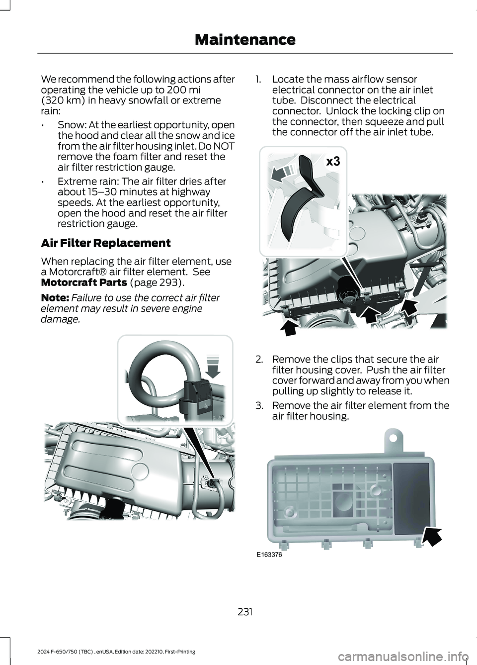
1.Locate the mass airflow sensorelectrical connector on the air inlettube. Disconnect the electricalconnector. Unlock the locking clip onthe connector, then squeeze and pullthe connector off the air inlet tube.
2.Remove the clips that secure the airfilter housing cover. Push the air filtercover forward and away from you whenpulling up slightly to release it.
3.Remove the air filter element from theair filter housing.
231
2024 F-650/750 (TBC) , enUSA, Edition date: 202210, First-PrintingMaintenanceE317651 x3E317652 E163376
Page 238 of 386
10.Reconnect the mass air flow sensorelectrical connector to the outlettube. Make sure the locking tab onthe connector is in the lockedposition.
DRAINING THE FUEL FILTER
WATER TRAP - 6.7L DIESEL
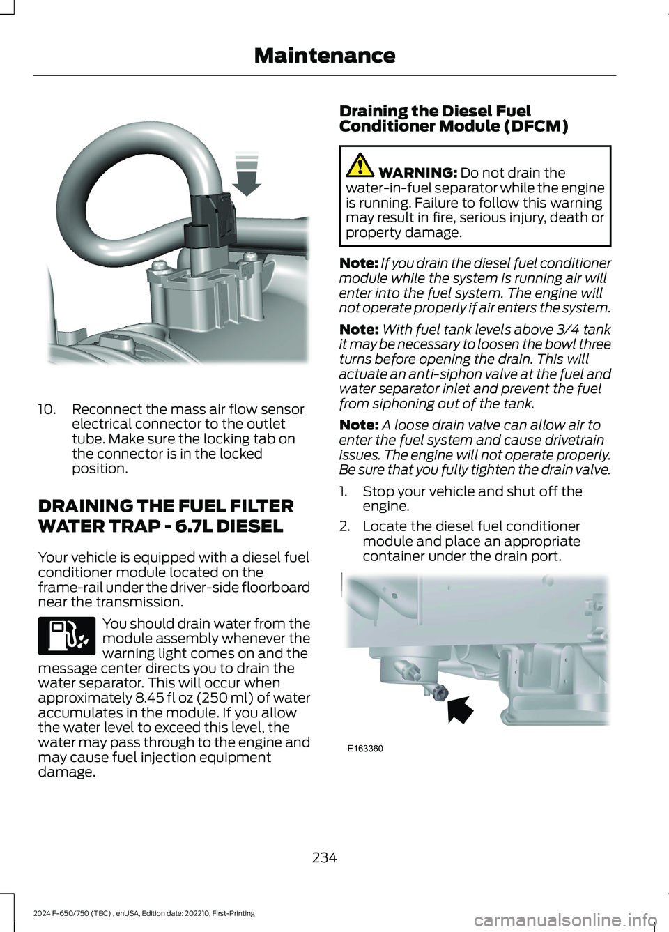
Your vehicle is equipped with a diesel fuelconditioner module located on theframe-rail under the driver-side floorboardnear the transmission.
You should drain water from themodule assembly whenever thewarning light comes on and themessage center directs you to drain thewater separator. This will occur whenapproximately 8.45 fl oz (250 ml) of wateraccumulates in the module. If you allowthe water level to exceed this level, thewater may pass through to the engine andmay cause fuel injection equipmentdamage.
Draining the Diesel FuelConditioner Module (DFCM)
WARNING: Do not drain thewater-in-fuel separator while the engineis running. Failure to follow this warningmay result in fire, serious injury, death orproperty damage.
Note:If you drain the diesel fuel conditionermodule while the system is running air willenter into the fuel system. The engine willnot operate properly if air enters the system.
Note:With fuel tank levels above 3⁄4 tankit may be necessary to loosen the bowl threeturns before opening the drain. This willactuate an anti-siphon valve at the fuel andwater separator inlet and prevent the fuelfrom siphoning out of the tank.
Note:A loose drain valve can allow air toenter the fuel system and cause drivetrainissues. The engine will not operate properly.Be sure that you fully tighten the drain valve.
1.Stop your vehicle and shut off theengine.
2.Locate the diesel fuel conditionermodule and place an appropriatecontainer under the drain port.
234
2024 F-650/750 (TBC) , enUSA, Edition date: 202210, First-PrintingMaintenanceE317619 E163360
Page 240 of 386
Note: Do not use stop leak pellets, coolingsystem sealants, or non-specified additivesas they can cause damage to the enginecooling or heating systems. Resultingcomponent damage may not be covered bythe vehicle warranty.
It is very important to use predilutedcoolant approved to the correctspecification to avoid plugging the smallpassageways in the engine cooling system.See Cooling System Capacity andSpecification (page 301). Do not mixdifferent colors or types of coolant in yourvehicle. Mixing of engine coolants or usingan incorrect coolant may harm the engineor cooling system components and maynot be covered by the vehicle warranty.
Note: Coolants marketed for all makes andmodels may not be approved to Fordspecifications and may cause damage tothe cooling system. Resulting componentdamage may not be covered by the vehicleWarranty.
If the coolant level is at or below theminimum mark, add prediluted coolantimmediately.
For vehicles with overflow coolant systemswith a non-pressurized cap on the coolantrecovery system, add coolant to thecoolant recovery reservoir when the engineis cool. Add prediluted coolant to themaximum level. For all vehicles which havea coolant degas system with a pressurizedcap, or if it is necessary to remove thecoolant pressure relief cap on the radiator,follow these steps to add engine coolant:
1.Turn the engine off and let it cool.
2.Unscrew the cap slowly. Any pressureescapes as you unscrew the cap.
3.Fill the coolant reservoir slowly withprediluted engine coolant to within theminimum and maximum range on theengine coolant reservoir. If youremoved the radiator cap in anoverflow system, fill the radiator until
the coolant is visible and the radiatoris almost full. If coolant is added tobring the level within the minimum andmaximum range when the engine is notcold, the system may remain underfilled.
4.Replace the coolant reservoir cap, turnit clockwise until you feel a strongresistance.
5.Check the coolant level in the coolantreservoir the next few times you driveyour vehicle. If necessary, add enoughprediluted engine coolant to bring thecoolant level to the proper level.
Note:If prediluted coolant is not available,use the approved antifreeze concentratediluting it to 50/50 with distilled water. SeeCooling System Capacity andSpecification (page 301). Using water thathas not been deionized may contribute todeposit formation, corrosion or plugging ofthe small cooling system passageways.
If you have to add more than 1.1 qt (1 L) ofengine coolant per month, have yourvehicle checked as soon as possible.Operating an engine with a low level ofcoolant can result in engine overheatingand possible engine damage.
Note:During normal vehicle operation, thecoolant may change color from orange topink or light red. As long as the coolant isclear and uncontaminated, this color changedoes not indicate the coolant has degradednor does it require the coolant to be drained,the system to be flushed, or the coolant tobe replaced.
In case of emergency, you can add a largeamount of water without predilutedcoolant to reach a vehicle service location.On arrival do the following:
1.Drain the cooling system.
2.Chemically clean the cooling system.We recommend Motorcraft PremiumCooling System Flush.
236
2024 F-650/750 (TBC) , enUSA, Edition date: 202210, First-PrintingMaintenance
Page 243 of 386
WARNING: To reduce the risk ofpersonal injury, make sure the engine iscool before unscrewing the coolantpressure relief cap. The cooling systemis under pressure. Steam and hot liquidcan come out forcefully when you loosenthe cap slightly.
WARNING: Do not add coolantfurther than the MAX mark.
When the engine is cold, check theconcentration and level of the coolant atthe intervals listed in the scheduledmaintenance information. See ScheduledMaintenance (page 325).
Note:Make sure that the coolant level isbetween the MIN and MAX marks on thecoolant reservoir.
Note: Coolant expands when it is hot. Thelevel may extend beyond the MAX mark.
Maintain coolant concentration within48% to 50%, which equates to a freezepoint between -30°F (-34°C) and -34°F(-37°C). Check the coolant concentrationusing a refractometer. We do notrecommend the use of hydrometers orcoolant test strips for measuring coolantconcentration.
Adding Coolant
WARNING: Do not add enginecoolant when the engine is on or thecooling system is hot. Failure to followthis instruction could result in personalinjury.
WARNING: Do not remove thecoolant reservoir cap when the engine ison or the cooling system is hot. Wait 10minutes for the cooling system to cooldown. Cover the coolant reservoir capwith a thick cloth to prevent thepossibility of scalding and slowly removethe cap. Failure to follow this instructioncould result in personal injury.
Note: Automotive fluids are notinterchangeable. Do not use coolant orwindshield washer fluid outside of itsspecified function and vehicle location.
Note: Do not use stop leak pellets, coolingsystem sealants, or non-specified additivesas they can cause damage to the enginecooling or heating systems. Resultingcomponent damage may not be covered bythe vehicle Warranty.
It is very important to use predilutedcoolant approved to the correctspecification in order to avoid plugging thesmall passageways in the engine coolingsystem. See Cooling System Capacityand Specification (page 302). Do not mixdifferent colors or types of coolant in yourvehicle. Mixing of engine coolants or usingan incorrect coolant may harm the engineor cooling system components and maynot be covered by the vehicle Warranty.
Note: Coolants marketed for all makes andmodels may not be approved to ourspecifications and may cause damage tothe cooling system. Resulting componentdamage may not be covered by the vehicleWarranty.
If the coolant level is at or below theminimum mark, add prediluted coolantimmediately.
239
2024 F-650/750 (TBC) , enUSA, Edition date: 202210, First-PrintingMaintenance
Page 253 of 386

4.On the wall or screen you will observea flat zone of high intensity lightlocated at the top of the right handportion of the beam pattern. If the topedge of the high intensity light zone isnot at the horizontal reference line, theheadlamp will need to be adjusted.
5.Locate the vertical adjuster on eachheadlamp. Using a Phillips #2screwdriver, turn the adjuster eitherclockwise or counterclockwise in orderto adjust the vertical aim of theheadlamp.
6.Repeat Steps 3 thru 5 to adjust theother headlamp.
7.Close the hood and turn off the lamps.
Horizontal Aim Adjustment
Horizontal aim is not required for thisvehicle and is not adjustable.
WASHER FLUID CHECK
WARNING: If you operate yourvehicle in temperatures below 40°F(5°C), use washer fluid with antifreezeprotection. Failure to use washer fluidwith antifreeze protection in coldweather could result in impairedwindshield vision and increase the riskof injury or accident.
Add fluid to fill the reservoir if the level islow. Only use a washer fluid that meetsFord specifications. See Capacities andSpecifications (page 291).
State or local regulations on volatileorganic compounds may restrict the useof methanol, a common windshield washerantifreeze additive. Washer fluidscontaining non-methanol antifreezeagents should be used only if they providecold weather protection without damagingthe vehicle’s paint finish, wiper blades orwasher system.
FUEL FILTER - 7.3L
Your vehicle is equipped with a lifetimefuel filter that is integrated with the fueltank. Regular maintenance or replacementis not needed.
CHECKING THE WIPER
BLADES
249
2024 F-650/750 (TBC) , enUSA, Edition date: 202210, First-PrintingMaintenanceE142465 E163806 E142463
Page 256 of 386
Regular fuel filter changes are animportant part of engine maintenance;failing to keep with the scheduledmaintenance could lead to engineperformance issues and fuel injectionsystem damage. See ScheduledMaintenance (page 325).
Use only recommended service partsconforming to specifications. SeeMotorcraft Parts (page 293).
Note:Using fuel that has high levels ofimpurities may require more frequent filterreplacements than the service intervalspecifies.
Diesel Fuel Conditioner ModuleFilter
Removal
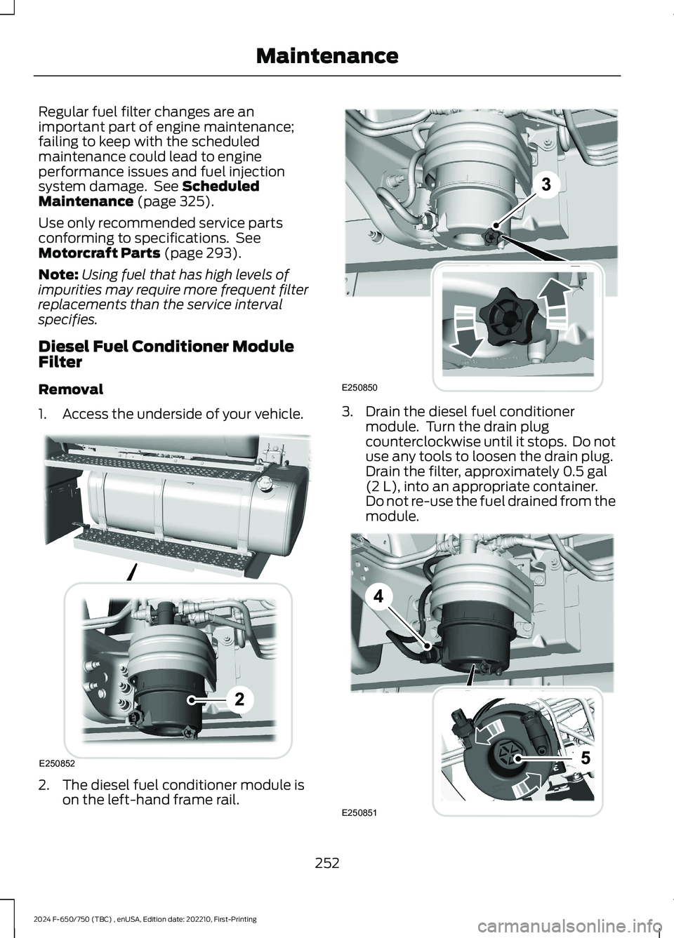
1.Access the underside of your vehicle.
2.The diesel fuel conditioner module ison the left-hand frame rail.
3.Drain the diesel fuel conditionermodule. Turn the drain plugcounterclockwise until it stops. Do notuse any tools to loosen the drain plug.Drain the filter, approximately 0.5 gal(2 L), into an appropriate container.Do not re-use the fuel drained from themodule.
252
2024 F-650/750 (TBC) , enUSA, Edition date: 202210, First-PrintingMaintenanceE250852 E250850 E250851
Page 257 of 386
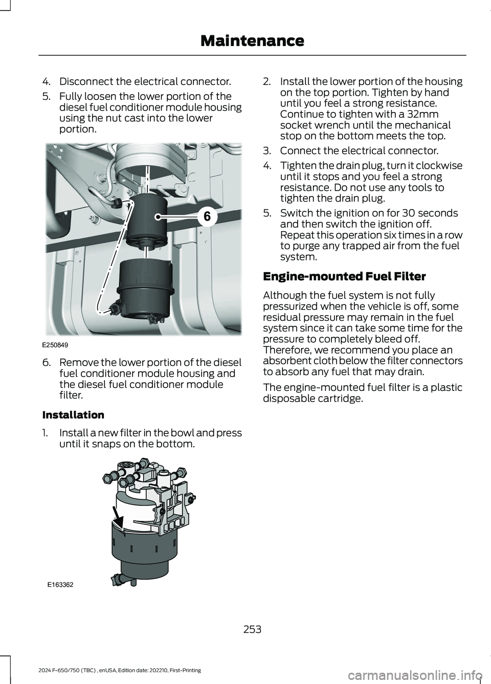
4.Disconnect the electrical connector.
5.Fully loosen the lower portion of thediesel fuel conditioner module housingusing the nut cast into the lowerportion.
6.Remove the lower portion of the dieselfuel conditioner module housing andthe diesel fuel conditioner modulefilter.
Installation
1.Install a new filter in the bowl and pressuntil it snaps on the bottom.
2.Install the lower portion of the housingon the top portion. Tighten by handuntil you feel a strong resistance.Continue to tighten with a 32mmsocket wrench until the mechanicalstop on the bottom meets the top.
3.Connect the electrical connector.
4.Tighten the drain plug, turn it clockwiseuntil it stops and you feel a strongresistance. Do not use any tools totighten the drain plug.
5.Switch the ignition on for 30 secondsand then switch the ignition off.Repeat this operation six times in a rowto purge any trapped air from the fuelsystem.
Engine-mounted Fuel Filter
Although the fuel system is not fullypressurized when the vehicle is off, someresidual pressure may remain in the fuelsystem since it can take some time for thepressure to completely bleed off.Therefore, we recommend you place anabsorbent cloth below the filter connectorsto absorb any fuel that may drain.
The engine-mounted fuel filter is a plasticdisposable cartridge.
253
2024 F-650/750 (TBC) , enUSA, Edition date: 202210, First-PrintingMaintenanceE250849 E163362
Page 259 of 386
AIR INDUCTION SYSTEM
INSPECTION
WARNING: When performingmaintenance to any turbocharged enginewith engine air inlet piping disconnected,keep loose clothing, jewelry and long hairaway from the engine air inlet piping. Aturbocharger compressor air inletprotective shield should be installed overthe turbocharger air inlet to reduce therisk of personal injury or death.
Perform a complete inspection of the airinduction system annually.
In areas where road salt is used,disassemble the joints of each aluminumcomponent and inspect for salt build-upand presence of chlorine that can causealuminum particles to flake off and enterthe engine combustion chambers. Ifevidence of corrosion is found (usually atthe pipe connections), use a wire brush toclean the inside of the pipes and inside therubber hoses.
If pitting is evident at the joint ends of theintake pipes, use Motorcraft SiliconeGasket and Sealant TA-30 to seal thejoints. Make sure no excess material, whichcan pull into the engine, is on the inside ofthe pipes. If the service condition of thepipes, hoses or clamps is questionable,replace the defective part(s).
Make sure to clean all dust and debris outof the pipes and couplings with a clean,damp rag before reassembly.
Chassis-mounted Charge AirCooler
Visually inspect the core assembly fordebris and clogging of external fins withthe engine off.
Before engine operation, remove any debrisblocking the core.
•Turbocharger-to-charge air cooler.
•Charge air cooler-to-intake manifoldpipe.
•Mounting bracket.
•Chassis-mounted charge air coolercore.
Inspect air intake piping:
•Check for accumulation of saltdeposits (where applicable). If present,disassemble and clean the completeair intake piping system. If pitting isevident on the intake piping, useMotorcraft Silicone Gasket and SealantTA-30 to seal joints against leakage.
•Check for loose hoses and clamps.
•Check for ruptured or collapsed hoses.
•Check air cleaner housing for cracks.
EXHAUST SYSTEM
INSPECTION
Note:If your vehicle is equipped with acatalytic converter or muffler, do not blendwaste oil with diesel fuel. Operate only onultra-low sulfur (less than 15 parts permillion sulfur) diesel fuel with a cetanevalue of 45 or higher.
If your diesel engine is equipped with acatalytic converter, it is important to reviewthe maintenance schedule to make sureproper functioning of the catalyticconverter. Also, take precautions not todamage the catalytic converter whenservicing your engine or storing yourvehicle.
255
2024 F-650/750 (TBC) , enUSA, Edition date: 202210, First-PrintingMaintenance