2024 FORD F650/750 Port
[x] Cancel search: PortPage 261 of 386
as a stroke indicator to aid inadjustment checks. If the push rod isclean and the brakes are out ofadjustment, you can see the orangemarker protruding from the chamberwhen the brakes are applied.
•Checking the brake lining (every serviceinterval). When brake linings or blockswear within 0.063 in (1.6 mm) theymust be replaced.
•Periodic checking (every serviceinterval) of the air compressor filter.Check the filter minder and when theindicator is near or on the red linemarked Service, replace the filter andreset the service filter minder.
Do not back off or disconnect the frontbrakes so that they are less effective,letting the rear brakes do all the stoppingof your vehicle. Do not overlook the brakeson the trailer either. Brake condition on thetrailer is just as important as the tractor.Proper brake balance on trucks andtractor-trailers is essential for effectivebraking.
Once a year, inspect the entire brakesystem:
•Rubber components for deterioration.A qualified technician should inspectthese components and replace themas necessary. Replacement intervalsvary according to the severity andlength of vehicle service.
•Condition of brake drums, brakechambers and slack adjusters.
•System for air leaks.
•Hose or pipes for rust, damage anddeterioration.
•Operation of service and parkingbrakes.
Periodically inspect parts such as air brakechamber diaphragm, air compressor andair cleaner. Replace any parts if you canconsider them unserviceable.
Air Dryer
Climactic conditions affect performanceof desiccant or after-cooler type air dryers.You must establish a maintenanceschedule for each specific operation.
The use of an air dryer on a vehicle doesnot eliminate the need to drain the airreservoirs periodically.
Inspect for moisture in the air system byopening reservoirs, draincocks or valvesand checking for presence of water. Thepresence of small amounts of water dueto condensation is normal and is not anindication that the dryer is not functioningproperly.
Replace or rebuild the desiccant cartridgewhen you determine that the desiccant iscontaminated and does not have adequatewater absorption capacity. The desiccantchange interval may vary. A generalrecommendation is to replace thedesiccant every 12 months (yearly). Ifexperience has shown that extended orshortened life has resulted for a particularinstallation, then the yearly interval can beincreased or decreased accordingly.
Draining the Air Brake Reservoir
WARNING: Failure to drain airbrake reservoirs can result in a reductionor loss of braking ability due to fluidaccumulation in the reservoir and/orpossible freeze-up during cold weather.
Completely drain all the air brake reservoirsdaily by opening the draincock at the endsof the tanks. (Where accessible.Pull-chains are used when the drains areundercab or otherwise inaccessible.) Closethe draincock after draining. Manually drain
257
2024 F-650/750 (TBC) , enUSA, Edition date: 202210, First-PrintingMaintenance
Page 262 of 386
any air tanks equipped with automaticmoisture ejector valves, as required, tomaintain a dry air system. Contact anauthorized dealer if you are unsure of theair reservoir locations or the drainingprocedure.
Hydraulic Brakes
Establish a regular schedule for periodiccleaning, lubrication and adjustmentinspection based on vehicle use. Exactmaintenance intervals are difficult topredetermine due to vehicle applicationsand operating conditions. If you areuncertain of the proper schedule for yourvehicle, contact an authorized dealer.
Regular inspections should include:
•Checking the brake lining (every serviceinterval). Establish inspection intervalsthat provide for lining replacementbefore damage to the disc occurs.Excessive lining wear may expose thebacking plate to the disc causingscoring of the disc faces. A qualifiedtechnician should perform this
inspection and keep to instructionsprovided by the service manual.Hydraulic brake systems arepower-assisted. There is a greatreduction in braking capabilitieswithout engine assist.
•Proper fluid level. The level should beat the bottom edge of the ring on eachreservoir fill port. Do not fill the mastercylinder to the top of the reservoir. Iffluid level requires attention tomaintain a proper master cylinder level,this is an indication of either severeoperation (pad wear) or fluid leakage.A more frequent and thorough brakeinspection is required.
•Brake lines, hoses and fittings. Repairor replace brake line tubes, hoses orfittings as required. Inspect thesecomponents every 4,000 mi(6,000 km) for the following.
•Lines for kinks, dents, corrosion orrupture.
•Hoses for abrasions, kinks, softspots or rupture, collapse, cracks,twists or loose frame supports.When replacing a hose, be surethere is adequate clearance to thehose to avoid an abrasion to thenew hose.
•All connections for leaks.
Driveline Parking Brake
WARNING: Use wheel chocks andexercise caution when inspecting underthe vehicle. A vehicle roll-away couldresult in property damage, personal injuryor death.
A qualified technician should adjust theparking brake and keep to the instructionsin the service manual.
258
2024 F-650/750 (TBC) , enUSA, Edition date: 202210, First-PrintingMaintenance
Page 263 of 386
AXLE INSPECTION
Front Axle
Maintaining the front axle alignment tospecifications is very important. A qualifiedtechnician should check and maintain thealignment.
Regular inspections should include:
•Toe-in inspection and adjustment (ifnecessary), particularly with radialtires.
•Checking for proper tightness of axlemounting U-bolt nuts, attaching ormounting bolts and nuts.
•Checking the axle for damage, binding,worn parts and adequate lubrication.
•Checking the kingpins for excessivewear. Also, perform this check duringother scheduled maintenance, forexample as tire rotation or service,wheel bearing service and alignment.See the workshop manual for properprocedures.
Toe-in
It is essential to maintain correct toe-inand tire pressure for optimum tire wear.
Inspecting steer axle tires in the first3,000–10,000 mi (5,000–16,000 km)generally shows if tires are wearingnormally.
Rapid outside shoulder wear on both tiresindicates too much toe-in.
Rapid inside shoulder wear on both tiresindicates too much toe-out.
In P&D-type service, there can be aleft-to-right steer tire tread life differentialup to 40% depending on routes and othervariables.
Follow the tire manufacturer'srecommended cold inflation pressure forthe tire size, load range (ply rating) andsteer axle loading typical for their operation(each steer axle tire equals ½ steer axleloading).
Special applications may warrant a settingbased on experience with the type of tireoperating loads and conditions. Radial tiresare more sensitive to toe-in setting thanbias ply tires. Fine tuning school busalignment to line-haul truck standardsdoes not drastically improve tire tread life.
STEERING SYSTEM
INSPECTION
WARNING: Failure to maintain thesteering system in proper condition cancause reduced steering ability resultingin property damage, personal injury ordeath.
Note:Have any steering problemsimmediately corrected by a qualified servicetechnician.
Ask your service technician to examine thesteering mechanism. Only minoradjustments may be necessary.
Regular inspections should include:
•Checking the tie rod, drag link endclamp bolts and ball joints for propertightness.
•Checking for installation and spread ofcotter pins and tightness of nuts atboth ends of the tie rod and drag link.
•Checking that the pitman arm (steeringarm at steering gear) mounting is tightand locked. Check system for leaks orhose chafing. Repair immediately, ifnecessary.
259
2024 F-650/750 (TBC) , enUSA, Edition date: 202210, First-PrintingMaintenance
Page 264 of 386

•Maintaining proper steering gear andpower steering pump lubricant levels.
•Checking steering column joint boltsand steering linkage, particularly forbody-to-chassis clearance.
Steering Column Joint Bolts
As a good maintenance practice, checksteering column joint bolt tightness every60,000 mi (96,000 km) or annually,whichever occurs first. Do not overtightenthe bolts.
Hydraulic System
Whenever draining and refilling the powersteering's hydraulic system for any reason,bleed air from the system before returningthe vehicle to service. Failure to bleed thehydraulic system properly can result indegradation of power system performance.
Consult an authorized dealer who is awareof the proper procedures for filling andbleeding the system.
SUSPENSION SYSTEM
INSPECTION (IF EQUIPPED)
Note:Do not adjust air suspension heightto any setting other than the specifiedsetting. Altering the height setting changesthe driveline angle and may result inunwarrantable component damage, suchas transmission component damage.
Verify drive axle air suspension height andheight control valve performance at engineoil change intervals.
Periodically check:
•Condition of spring leaves for evidenceof fatigue, bending or breakage.
•Condition of suspension mountingbrackets and bushings.
•Torque rod mounting fasteners fortightness.
•For proper suspension alignment.Maintain proper alignment at all times.
•U-bolts. After the chassis has beenoperating under load for 1,000 mi(1,600 km) or six months (whichevercomes first), the U-bolt nuts must bere-torqued. Re-torque the U-bolt nutsevery 37,000 mi (60,000 km)thereafter. Clean and lubricate theU-bolt and nut threads and seats tomake sure a like new condition whenre-torqueing. See Spring U-BoltCheck (page 261).
FRAME AND TOW HOOK
INSPECTION
Your vehicle's chassis is manufacturedwith frame rails of either HSLA steel orheat-treated steel. Handle each in aspecific manner to make sure maximumservice life. Consult the service manual oran authorized dealer before attemptingframe repair or modification.
It is important, particularly on vehicles thatuse tow hooks frequently, to inspect thefront and rear tow hooks for damage or aloose mounting.
REAR AXLE FLUID CHECK
Your rear axle may have an optionalsynthetic lubricant that allows the use ofextended service intervals. A tag on thefiller plug identifies the use of the syntheticlubricant.
Only use a lubricant that meetsmanufacturer specifications. Use of anon-approved rear axle lubricant maycause internal axle component damage.See Rear Axle Fluid Capacity andSpecification (page 311).
Checking the Fluid Level
1.Park your vehicle on level ground.
260
2024 F-650/750 (TBC) , enUSA, Edition date: 202210, First-PrintingMaintenance
Page 270 of 386
CLEANING THE INSTRUMENT
PANEL AND INSTRUMENT
CLUSTER LENS
WARNING: Do not use chemicalsolvents or strong detergents whencleaning the steering wheel orinstrument panel to avoid contaminationof the airbag system.
Note:Follow the same procedure ascleaning leather seats for cleaning leatherinstrument panels and leather interior trimsurfaces.
Clean the instrument panel and clusterlens with a clean, damp and soft cloth,then use a clean, dry and soft cloth to drythese areas.
•Avoid cleaners or polishes that increasethe gloss of the upper portion of theinstrument panel. The dull finish in thisarea helps protect you fromundesirable windshield reflection.
•Do not use any household cleaningproducts or glass cleaners as thesemay damage the finish of theinstrument panel, interior trim andcluster lens.
•Wash or wipe your hands clean if youhave been in contact with certainproducts such as insect repellent andsuntan lotion to avoid possible damageto the interior painted surfaces.
•Do not allow air fresheners and handsanitizers to spill onto interior surfaces.If a spill occurs, wipe off immediately.Your warranty may not cover thesedamages.
If a staining liquid like coffee or juice hasbeen spilled on the instrument panel or oninterior trim surfaces:
1.Wipe up spilled liquid using a clean,soft cloth as quickly as possible.
2.Use Motorcraft Premium Leather andVinyl Cleaner or a commerciallyavailable leather cleaning product forautomotive interiors. Test any cleaneror stain remover on an inconspicuousarea.
3.Alternatively, wipe the surface with aclean, soft cloth and a mild soap andwater solution. Dry the area with aclean, soft cloth.
4.If necessary, apply more soap andwater solution or cleaning product toa clean, soft cloth and press it onto thesoiled area. Allow this to set at roomtemperature for 30 minutes.
5.Remove the soaked cloth, then with aclean, damp cloth, use a rubbingmotion for 60 seconds on the soiledarea.
6.Dry the area with a clean, soft cloth.
REPAIRING MINOR PAINT
DAMAGE
We recommend that you contact anauthorized dealer to identify your vehiclecolor code. Authorized dealers havetouch-up paint to match your vehicle'scolor.
Before repairing minor paint damage, usea cleaner to remove particles such as birddroppings, tree sap, insect deposits, tarspots, road salt and industrial fallout.
Read the instructions before using cleaningproducts.
CLEANING THE WHEELS
1.Regularly clean them with a wheelcleaner. We recommend that you useFord approved wheel cleaner ifavailable.
2.Remove dirt and brake dust with asponge.
266
2024 F-650/750 (TBC) , enUSA, Edition date: 202210, First-PrintingVehicle Care
Page 273 of 386
TIRE CARE
Glossary of Tire Terminology
*Tire label: A label showing theoriginal equipment tire sizes,recommended inflation pressureand the maximum weight thevehicle can carry.
*Tire Identification Number: Anumber on the sidewall of eachtire providing information aboutthe tire brand and manufacturingplant, tire size and date ofmanufacture. Also referred to asDOT code.
*Inflation pressure: A measureof the amount of air in a tire.
*Standard load: A class ofP-metric or Metric tires designedto carry a maximum load at setpressure. For example: ForP-metric tires 35 psi (241 kPa) andfor Metric tires 36 psi (248 kPa).Increasing the inflation pressurebeyond this pressure does notincrease the tire’s load carryingcapability.
*Extra load: A class of P-metricor Metric tires designed to carry aheavier maximum load at 42 psi(290 kPa). Increasing the inflationpressure beyond this pressuredoes not increase the tire’s loadcarrying capability.
*kPa: Kilopascal, a metric unit ofair pressure.
*PSI: Pounds per square inch, astandard unit of air pressure.
*Cold tire pressure: The tirepressure when the vehicle hasbeen stationary and out of directsunlight for an hour or more andprior to the vehicle being driven for1 mi (1.6 km).
*Recommended inflationpressure: The cold inflationpressure is found on the SafetyCompliance Certification Label,located in the driver's door jam.
*Bead area of the tire: Area ofthe tire next to the rim.
*Sidewall of the tire: Areabetween the bead area and thetread.
*Tread area of the tire: Area ofthe perimeter of the tire thatcontacts the road when mountedon the vehicle.
*Rim: The metal support (wheel)for a tire or a tire and tubeassembly upon which the tirebeads are seated.
Information Contained on theTire Sidewall
Both United States and CanadaFederal regulations require tiremanufacturers to placestandardized information on thesidewall of all tires. Thisinformation identifies anddescribes the fundamentalcharacteristics of the tire and alsoprovides a U.S. DOT TireIdentification Number for safetystandard certification and in caseof a recall.
269
2024 F-650/750 (TBC) , enUSA, Edition date: 202210, First-PrintingWheels and Tires
Page 274 of 386
Information on P Type Tires
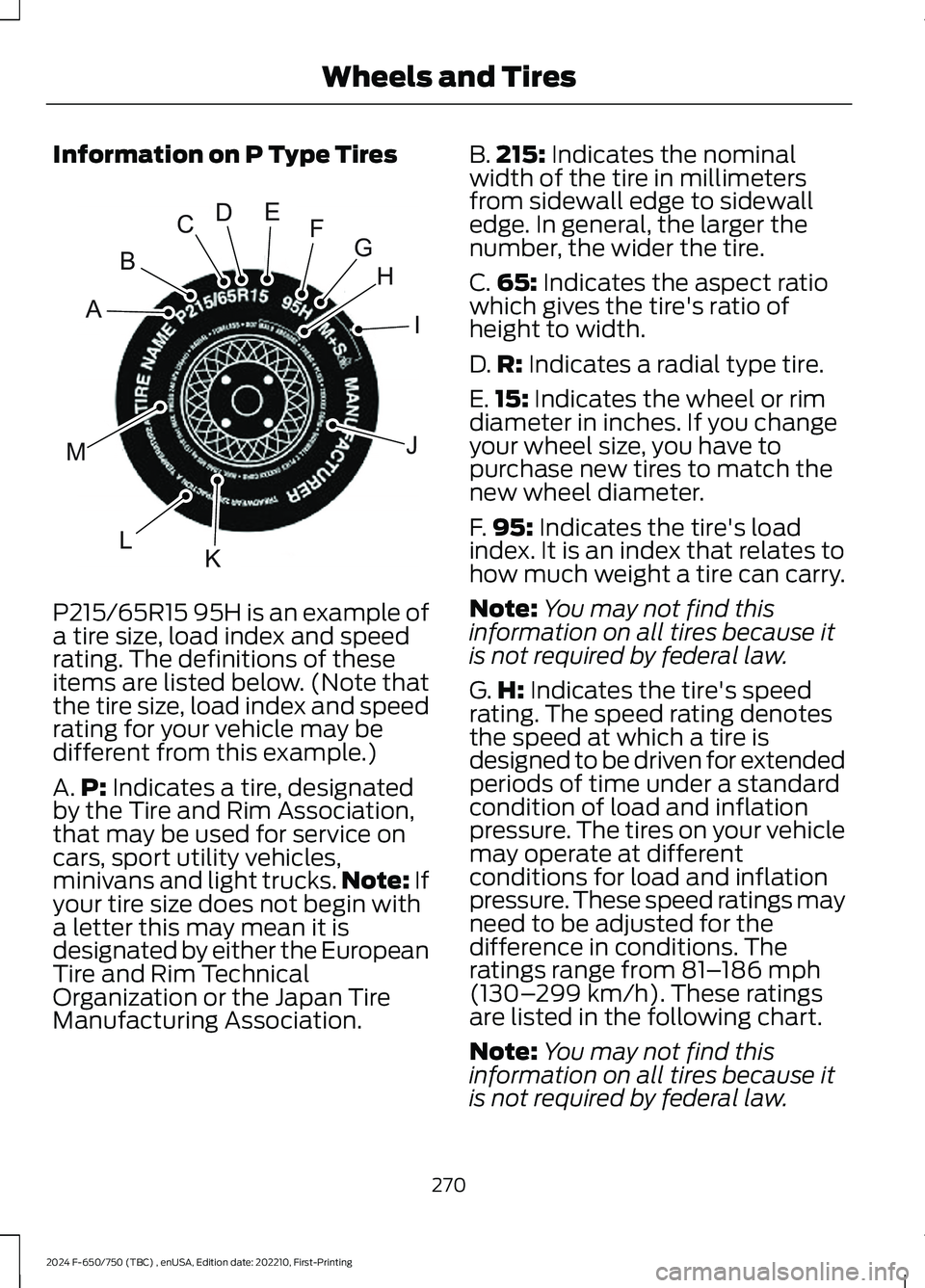
P215/65R15 95H is an example of
a tire size, load index and speedrating. The definitions of theseitems are listed below. (Note thatthe tire size, load index and speedrating for your vehicle may bedifferent from this example.)
A.P: Indicates a tire, designatedby the Tire and Rim Association,that may be used for service oncars, sport utility vehicles,minivans and light trucks.Note: Ifyour tire size does not begin witha letter this may mean it isdesignated by either the EuropeanTire and Rim TechnicalOrganization or the Japan TireManufacturing Association.
B.215: Indicates the nominalwidth of the tire in millimetersfrom sidewall edge to sidewalledge. In general, the larger thenumber, the wider the tire.
C.65: Indicates the aspect ratiowhich gives the tire's ratio ofheight to width.
D.R: Indicates a radial type tire.
E.15: Indicates the wheel or rimdiameter in inches. If you changeyour wheel size, you have topurchase new tires to match thenew wheel diameter.
F.95: Indicates the tire's loadindex. It is an index that relates tohow much weight a tire can carry.
Note:You may not find thisinformation on all tires because itis not required by federal law.
G.H: Indicates the tire's speedrating. The speed rating denotesthe speed at which a tire isdesigned to be driven for extendedperiods of time under a standardcondition of load and inflationpressure. The tires on your vehiclemay operate at differentconditions for load and inflationpressure. These speed ratings mayneed to be adjusted for thedifference in conditions. Theratings range from 81–186 mph(130–299 km/h). These ratingsare listed in the following chart.
Note:You may not find thisinformation on all tires because it
is not required by federal law.
270
2024 F-650/750 (TBC) , enUSA, Edition date: 202210, First-PrintingWheels and TiresHIJKLMABCDEFGE142543
Page 277 of 386
C.Maximum Load Dual lb (kg)at psi (kPa) cold: Indicates themaximum load and tire pressurewhen the tire is used as a dual;defined as four tires on the rearaxle (a total of six or more tires onthe vehicle).
D.Maximum Load Single lb(kg) at psi (kPa) cold: Indicatesthe maximum load and tirepressure when the tire is used asa single; defined as two tires(total) on the rear axle.
Information on T Type Tires
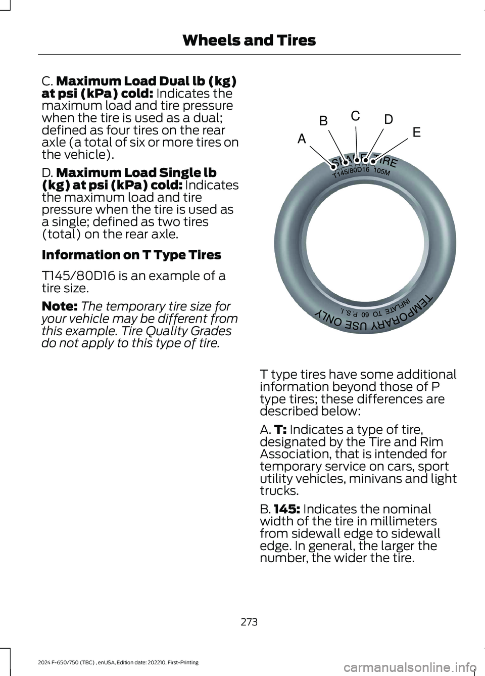
T145/80D16 is an example of atire size.
Note:The temporary tire size foryour vehicle may be different fromthis example. Tire Quality Grades
do not apply to this type of tire.
T type tires have some additionalinformation beyond those of Ptype tires; these differences aredescribed below:
A.T: Indicates a type of tire,designated by the Tire and RimAssociation, that is intended fortemporary service on cars, sportutility vehicles, minivans and lighttrucks.
B.145: Indicates the nominalwidth of the tire in millimetersfrom sidewall edge to sidewalledge. In general, the larger thenumber, the wider the tire.
273
2024 F-650/750 (TBC) , enUSA, Edition date: 202210, First-PrintingWheels and TiresABCDEE142545