2024 FORD F650/750 jump cable
[x] Cancel search: jump cablePage 122 of 386

•Incorrect fuel for climatic conditions.
•Incorrect engine oil viscosity forclimactic conditions.
Note:Some vehicles have a lifetime fuelfilter that is integrated with the fuel tank.Regular maintenance or replacement is notneeded.
Note:If these checks do not help youcorrect the concern, have your vehiclechecked as soon as possible.
Noise Emissions Warranty,Prohibited Tampering Acts andMaintenance
On January 1, 1978, Federal regulationbecame effective governing the noiseemission on trucks over 10,000 lb(4,536 kg) Gross Vehicle Weight Rating(GVWR). The preceding statementsconcerning prohibited tampering acts andmaintenance, and the noise warrantyfound in the Warranty Guide, areapplicable to complete chassis cabs over10,000 lb (4,536 kg) GVWR.
CATALYTIC CONVERTER
WARNING: Do not park, idle ordrive your vehicle on dry grass or otherdry ground cover. The emission systemheats up the engine compartment andexhaust system, creating the risk of fire.
WARNING: The normal operatingtemperature of the exhaust system isvery high. Never work around or attemptto repair any part of the exhaust systemuntil it has cooled. Use special care whenworking around the catalytic converter.The catalytic converter heats up to a veryhigh temperature after only a shortperiod of engine operation and stays hotafter the engine is switched off.
WARNING: Exhaust leaks mayresult in entry of harmful and potentiallylethal fumes into the passengercompartment. If you smell exhaustfumes inside your vehicle, have yourvehicle inspected immediately. Do notdrive if you smell exhaust fumes.
Your vehicle has various emission controlcomponents and a catalytic converter thatenables it to comply with applicableexhaust emission standards.
To make sure that the catalytic converterand other emission control componentscontinue to work properly:
•Do not crank the engine for more than10 seconds at a time.
•Do not run the engine with a spark pluglead disconnected.
•Do not push-start or tow-start yourvehicle. Use booster cables. See JumpStarting the Vehicle (page 190).
•Use only the specified fuel listed.
•Do not switch the ignition off when yourvehicle is moving.
•Avoid running out of fuel.
•Have the items listed in scheduledmaintenance information performedaccording to the specified schedule.
Note:Resulting component damage maynot be covered by the vehicle Warranty.
The scheduled maintenance items listedin scheduled maintenance information areessential to the life and performance ofyour vehicle and to its emissions system.
If you use anything other than Ford,Motorcraft or Ford-authorized parts formaintenance replacements or for serviceof components affecting emission control,such non-Ford parts should be equivalentto genuine Ford Motor Company parts inperformance and durability.
118
2024 F-650/750 (TBC) , enUSA, Edition date: 202210, First-PrintingEngine Emission Control
Page 194 of 386

HAZARD FLASHERS
Note:If used when the vehicle is notrunning, the battery loses charge. As a result,there may be insufficient power to restartyour vehicle.
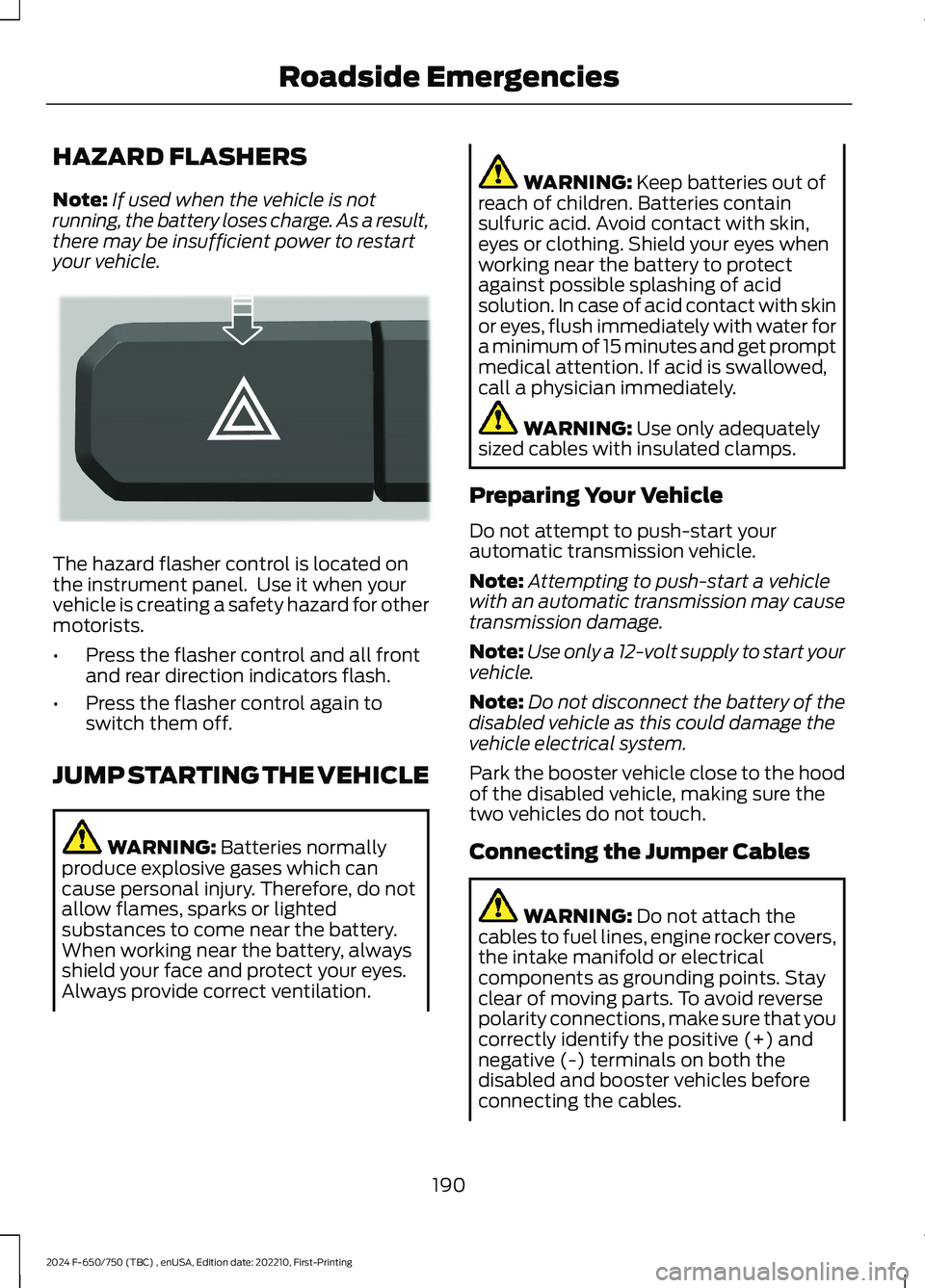
The hazard flasher control is located onthe instrument panel. Use it when yourvehicle is creating a safety hazard for othermotorists.
•Press the flasher control and all frontand rear direction indicators flash.
•Press the flasher control again toswitch them off.
JUMP STARTING THE VEHICLE
WARNING: Batteries normallyproduce explosive gases which cancause personal injury. Therefore, do notallow flames, sparks or lightedsubstances to come near the battery.When working near the battery, alwaysshield your face and protect your eyes.Always provide correct ventilation.
WARNING: Keep batteries out ofreach of children. Batteries containsulfuric acid. Avoid contact with skin,eyes or clothing. Shield your eyes whenworking near the battery to protectagainst possible splashing of acidsolution. In case of acid contact with skinor eyes, flush immediately with water fora minimum of 15 minutes and get promptmedical attention. If acid is swallowed,call a physician immediately.
WARNING: Use only adequatelysized cables with insulated clamps.
Preparing Your Vehicle
Do not attempt to push-start yourautomatic transmission vehicle.
Note:Attempting to push-start a vehiclewith an automatic transmission may causetransmission damage.
Note:Use only a 12-volt supply to start yourvehicle.
Note:Do not disconnect the battery of thedisabled vehicle as this could damage thevehicle electrical system.
Park the booster vehicle close to the hoodof the disabled vehicle, making sure thetwo vehicles do not touch.
Connecting the Jumper Cables
WARNING: Do not attach thecables to fuel lines, engine rocker covers,the intake manifold or electricalcomponents as grounding points. Stayclear of moving parts. To avoid reversepolarity connections, make sure that youcorrectly identify the positive (+) andnegative (-) terminals on both thedisabled and booster vehicles beforeconnecting the cables.
190
2024 F-650/750 (TBC) , enUSA, Edition date: 202210, First-PrintingRoadside EmergenciesE304635
Page 195 of 386

WARNING: Do not attach the endof the positive cable to the studs orL-shaped eyelet located above thepositive (+) terminal of your vehicle’sbattery. High current may flow throughand cause damage to the fuses.
WARNING: Do not connect the endof the second cable to the negative (-)terminal of the battery to be jumped. Aspark may cause an explosion of thegases that surround the battery.
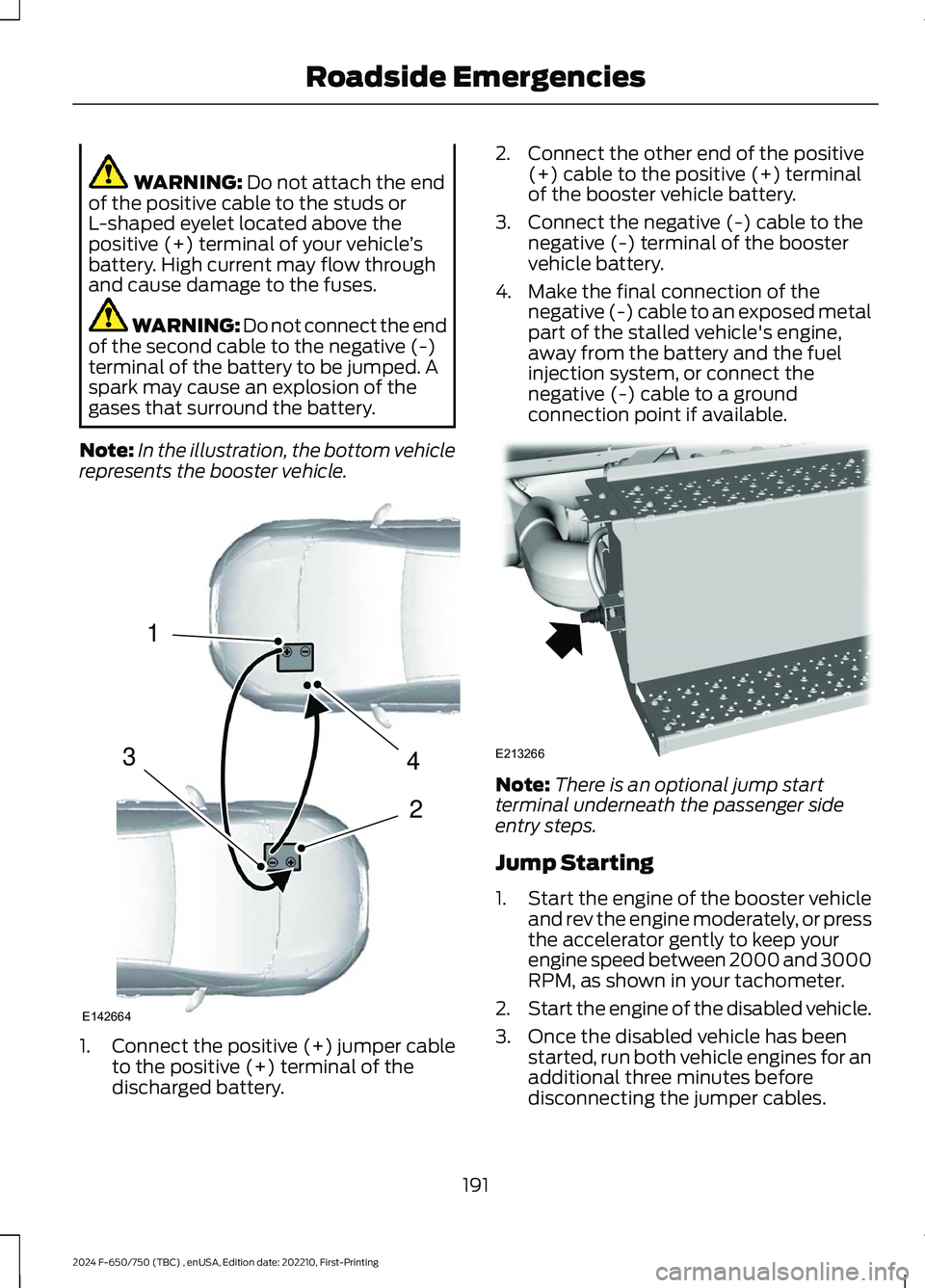
Note:In the illustration, the bottom vehiclerepresents the booster vehicle.
1.Connect the positive (+) jumper cableto the positive (+) terminal of thedischarged battery.
2.Connect the other end of the positive(+) cable to the positive (+) terminalof the booster vehicle battery.
3.Connect the negative (-) cable to thenegative (-) terminal of the boostervehicle battery.
4.Make the final connection of thenegative (-) cable to an exposed metalpart of the stalled vehicle's engine,away from the battery and the fuelinjection system, or connect thenegative (-) cable to a groundconnection point if available.
Note:There is an optional jump startterminal underneath the passenger sideentry steps.
Jump Starting
1.Start the engine of the booster vehicleand rev the engine moderately, or pressthe accelerator gently to keep yourengine speed between 2000 and 3000RPM, as shown in your tachometer.
2.Start the engine of the disabled vehicle.
3.Once the disabled vehicle has beenstarted, run both vehicle engines for anadditional three minutes beforedisconnecting the jumper cables.
191
2024 F-650/750 (TBC) , enUSA, Edition date: 202210, First-PrintingRoadside Emergencies4213E142664 E213266
Page 196 of 386

Removing the Jumper Cables
Remove the jumper cables in the reverseorder that they were connected.
1.Remove the negative (-) jumper cablefrom the disabled vehicle.
2.Remove the jumper cable on thenegative (-) terminal of the boostervehicle battery.
3.Remove the jumper cable from thepositive (+) terminal of the boostervehicle battery.
4.Remove the jumper cable from thepositive (+) terminal of the disabledvehicle battery.
5.Allow the engine to idle for at least oneminute.
TRANSPORTING THE VEHICLE
WARNING: Block the wheels tohelp prevent the vehicle from moving.
WARNING: Unexpected andpossibly sudden vehicle movement mayoccur if you do not take theseprecautions.
If you need to have your vehicle towed,contact a professional towing service or,if you are a member of a roadsideassistance program, your roadsideassistance service provider.
192
2024 F-650/750 (TBC) , enUSA, Edition date: 202210, First-PrintingRoadside Emergencies4132E142665 E143886
Page 258 of 386

Removal
1.Disconnect the fuel lines by squeezingthe connector tabs and pulling the linesstraight off.
2.Rotate the filter fully counterclockwiseuntil the peg is at the far end of the slot.
3.Pull the filter straight up from thebracket and discard the filter.
Installation
1.Install the new filter into the filterbracket. Turn the filter clockwise tolock it in place.
2.Reconnect the fuel lines.
3.Switch the ignition on for 30 secondsand then switch the ignition off.Repeat this operation six times in a rowto purge any trapped air from the fuelsystem.
ELECTRICAL SYSTEM
INSPECTION
Periodically inspect electrical connectorson the outside of the cab and on the engineand frame for corrosion and tightness.Exposed terminals, such as the fuel sender,cranking motor, alternator andfeed-through studs, should be cleaned andre-coated with a lubricant sealing greasesuch as Motorcraft Silicone Brake CaliperGrease and Dielectric Compound XG-3, orequivalent. This should include the groundcable connector for batteries, engine andcab as well as the jump-starting stud.
Accessory Feed Connections
Vehicle electrical systems are complex andoften include powertrain components,such as engine and transmission controls,instrument panels and ABS. While mostsystems operate on battery voltage (12volts), some systems can be as high as 90volts or as low as five volts. See theElectrical Circuit Diagram Manuals,available from your vehicle’s manufacturer,to make sure that any extra body lights andaccessory connections to circuits are bothappropriate and not overloaded. Do notmake modifications to any vehicle controlsystem without first contacting anauthorized dealer.
254
2024 F-650/750 (TBC) , enUSA, Edition date: 202210, First-PrintingMaintenanceE2262151 E22621423