2022 TOYOTA SUPRA warning
[x] Cancel search: warningPage 18 of 498

161-1. NOTES
third-party providers via servers of
the vehicle manufacturer. No direct
access to the vehicle and its data is
granted.
More information on CarData is
available on the Toyota Supra Con-
nect customer portal.
The eCall emergency call system
required by law enables manual or
automatic emergency calls to be
issued in the event of accidents, for
example.
The emergency calls are answered
by the public rescue coordination
centre.
For information on the eCall statu-
tory on-board emergency call sys-
tem based on the 112 emergency
call, as well as its operation and its
functions, see the chapter on emer-
gency calls.
The eCall service based on the 112
emergency call is a public service
of general interest and is provided
free of charge.
If a serious accident occurs, the
eCall statutory emergency call sys-
tem is activated automatically by
on-board sensors as a standard
feature. It is also triggered automat-
ically if the vehicle is equipped with
an intelligent emergency call sys-
tem that fails to wo rk in the event of
a serious accident.
The eCall statutory emergency call
system can also be triggered man-
ually if required.
If a critical system failure occurs
that would put the eCall statutory
emergency call system out of oper-
ation, the passengers receive a
warning.
For further information:
• Emergency call, see page 353.
• Malfunction, see page 354.
The eCall statutory emergency call
system processes personal data in
accordance with the following regu-
lations:
• Protection of personal data: Reg-
ulation 2016/679/EU of the Euro-
pean Parliament and of the
Council.
• Protection of personal data:
Directive 2002/58/EC of the
European Parliament and of the
Council.
Personal data is only processed for
the purpose of transmitting eCall
emergency calls to the standard-
ised European emergency call
number 112.
Statutory emergency call
system
Principle
General
Information on data processing
Page 32 of 498

302-1. QUICK REFERENCE
1Wipers
2 Instrument cluster
3 Turn indicator, high-beam head-
lights
4 Light switch element
Indicator and warning lamps can
illuminate in a variety of combina-
tions and colours.
When the engine starts or the
standby state is switched on, the
functionality of some lights is briefly
checked.
1 Exterior mirrors
2 Power window switches
3 Central locking system
4 Unlocking the boot lid
1 Selector lever
2 Controller
3 Auto Start & Stop cancel button
4 Sport mode switch
5 Park Assistant button
6 VSC OFF button
7 Toyota Supra Safety button
8 Parking brake
Toyota Supra Command brings
together the functions of a number
of switches. These functions can be
operated using the Controller and,
depending on the equipment ver-
sion, the touchscreen.
Displays and controls
Around the steering wheel
Indicator and warning lamps
Driver's door
1
2
3
4
321
4
Switch cluster
Toyota Supra Command
Principle
Page 44 of 498

422-1. QUICK REFERENCE
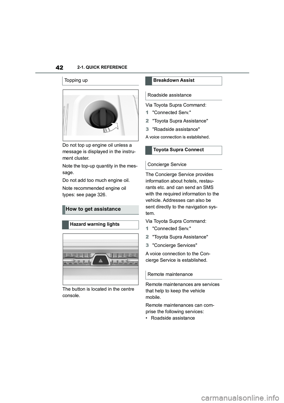
Do not top up engine oil unless a
message is displayed in the instru-
ment cluster.
Note the top-up quantity in the mes-
sage.
Do not add too much engine oil.
Note recommended engine oil
types: see page 326.
The button is located in the centre
console.
Via Toyota Supra Command:
1 "Connected Serv."
2 "Toyota Supra Assistance"
3 "Roadside assistance"
A voice connection is established.
The Concierge Service provides
information about hotels, restau-
rants etc. and can send an SMS
with the required information to the
vehicle. Addresses can also be
sent directly to the navigation sys-
tem.
Via Toyota Supra Command:
1 "Connected Serv."
2 "Toyota Supra Assistance"
3 "Concierge Services"
A voice connection to the Con-
cierge Service is established.
Remote maintenances are services
that help to keep the vehicle
mobile.
Remote maintenances can com-
prise the following services:
• Roadside assistance
Topping up
How to get assistance
Hazard warning lights
Breakdown Assist
Roadside assistance
Toyota Supra Connect
Concierge Service
Remote maintenance
Page 50 of 498

483-1. CONTROLS
13 Horn, entire area
14 To release the bonnet
P. 3 2 1
15 Unlocking the boot lid P.91
1 Control Display P.59
2 Hazard warning lights
P. 3 5 2
3 Ventilation P.266
4 Glove box P.274
5 Radio/multimedia, see Naviga-
tion system Owner's manual
6 Automatic air conditioning P.261
7 Controller with buttons P.60,
P. 6 1
8 Sport mode switch P.160
SPORT drive mode
Toyota Supra Safety P.205
Auto Start/Stop P.145
Parking Sensors P.50
Rear-view camera P.253
RCTA (Rear cross traffic alert)
function P.256
Park Assistant P.50
Vehicle Stability Control,
VSC P.229
9 Parking brake P.148
10 Automatic transmission selector
lever P.154
Around the centre console
1
4
23
5
6
7
89
10
11
Page 58 of 498

563-1. CONTROLS
1Depress the brake pedal.
2 Press the start/stop button.
The starting process is activated
automatically for a short time and
stops as soon as the engine starts.
Most of the indicator and warning
lamps in the instrument cluster are
illuminated for different lengths of
time.
Depending on the motorisation, full
drive power and the entire engine
speed range may not be available
until approx. 30 seconds after the
engine is started. In this case, the
vehicle will not accelerate in the
usual way, refer to page P.168.
1 With the vehicle at a standstill,
engage selector lever position P.
2 Press the start/stop button.
The engine is switched off. The vehicle
changes to standby state.
3 Apply the parking brake.
Switching on drive-ready
state
Principle
Drive-ready state is
switched on using
the start/stop button:
Automatic transmission
Petrol engine
Display in the instrument
cluster
READY in the instrument
cluster indicates that
drive-ready state is
switched on.
Switching off drive-ready
state
Page 93 of 498

91
3
3-1. CONTROLS
CONTROLS
The windows are closed for as long
as the button on the remote control
is pressed.
The exterior mirrors are folded in.
If the hazard warning lights are
switched on, the exterior mirrors
are not folded in.
The function is not available for the
first 10 seconds after locking.
• The interior light is switched on
unless it was switched off manu-
ally. To switch th e interior light
on/off manually, see page 191.
• Depending on the settings, the
exterior lights, see page 187, are
switched on.
The lighting functions may depend
on the ambient brightness.
To prevent the remote control from
being locked in, do not place the
remote control in the boot.
It is possible to set whether the
doors are unlocked when the boot
lid is opened with the remote con-
trol. For settings, see page 101.
On some equipment versions, the
doors are also unlocked each time.
Comfort closing
Safety notes
WA R N I N G
Parts of the body can become trapped when the comfort closing fea-
ture is operated. There is a danger of
injury. When the comfort closing fea-
ture is operating, make sure that the area of movement is kept clear.
Closing
Keep the button on the
remote control pressed after
locking.
Switching on the interior
light and exterior lights
With the vehicle locked,
press the button on the
remote control.
Boot lid
General
Safety notes
WA R N I N G
Parts of the body can become trapped when the boot lid is operated.
There is a danger of injury. When
opening and closing, make sure that the area of movement of the boot lid
is kept clear.
NOTICE
The boot lid swings rearwards and upwards when opened. There is a
danger of damage to property. When
opening and closing, make sure that the area of movement of the boot lid
is kept clear.
Unlocking
Press and hold the button on
the remote control for approx-
imately 1 second.
Page 97 of 498

95
3
3-1. CONTROLS
CONTROLS
Press the button, arrow 1, and pull
out the integrated key, arrow 2.
1 Pull the door handle outwards
with one hand and hold it.
2 Slide one finger of your other
hand under the cover from
behind and push the cover out-
wards.
Support the cover with your thumb, to
stop it falling out of the door handle.
3 Remove the cover.
4 Unlock or lock the door lock with
the integrated key.
The other doors must be unlocked
or locked from the inside.
The switched-on alarm system is
triggered when the door is opened
after being unlocked via the door
lock.
The alarm system is not switched
on if the vehicle is locked with the
integrated key.
In the event of an accident of suffi-
cient severity, the vehicle is auto-
matically unlocked. The hazard
warning lights and in terior lights illu-
minate.
Unlocking/locking using the
door lock
Alarm system
Central locking buttons
General
Page 105 of 498

103
3
3-1. CONTROLS
CONTROLS
is opened.
• Movements inside the vehicle.
• A change in the vehicle's incline,
for instance if an attempt is made
to jack it up and steal the wheels
or to raise it prior to towing away.
• An interruption in the power sup-
ply from the battery.
• Improper use of the socket for
on-board diagnosis OBD.
• The vehicle is locked while a
device is connected to the socket
for on-board diagnosis OBD.
Socket for on-board diagnosis
OBD, see page 332.
The alarm system indicates the fol-
lowing changes visually and audi-
bly:
• Audible alarm: Depending on
local regulations, the acoustic
alarm may be suppressed.
• Visual alarm: By flashing of the
hazard warning lights and, if
applicable, the headlights.
To safeguard the function of the
alarm system, do not modify the
system.
The alarm system is switched off
and on at the same time as the
vehicle is unlocked and locked via
the remote control or Smart Key
System.
The alarm system is triggered on
opening a door if the door has been
unlocked using the integrated key
in the door lock.
To stop the alarm, see page 104.
The boot lid can be opened even
with the alarm system switched on.
On closing the boot lid, it is locked
again and monitored, as long as the
doors are locked. The hazard warn-
ing lights flash once.
• Indicator lamp flashes every 2
seconds: The alarm system is
switched on.
• Indicator lamp flashes for
approximately 10 seconds
before it flashes every 2 sec-
onds: The interior movement
detector and tilt alarm sensor are
not active because doors, bon-
Switching on/off
Opening the doors when the
alarm system is switched on
Opening the boot lid with the
alarm system switched on
Indicator lamp on the
rear-view mirror