Page 301 of 498

299
5
5-1. MOBILITY
MOBILITY
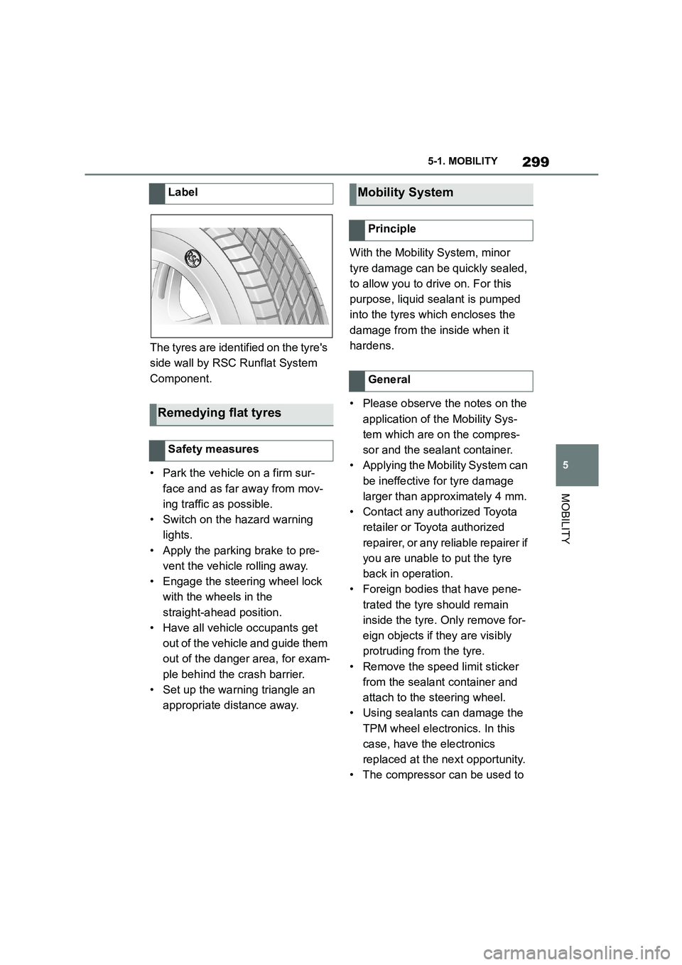
The tyres are identified on the tyre's
side wall by RSC Runflat System
Component.
• Park the vehicle on a firm sur-
face and as far away from mov-
ing traffic as possible.
• Switch on the hazard warning
lights.
• Apply the parking brake to pre-
vent the vehicle rolling away.
• Engage the steering wheel lock
with the wheels in the
straight-ahead position.
• Have all vehicle occupants get
out of the vehicle and guide them
out of the danger area, for exam-
ple behind the crash barrier.
• Set up the warning triangle an
appropriate distance away.
With the Mobility System, minor
tyre damage can be quickly sealed,
to allow you to drive on. For this
purpose, liquid sealant is pumped
into the tyres which encloses the
damage from the inside when it
hardens.
• Please observe the notes on the
application of the Mobility Sys-
tem which are on the compres-
sor and the sealant container.
• Applying the Mobility System can
be ineffective for tyre damage
larger than approximately 4 mm.
• Contact any authorized Toyota
retailer or Toyota authorized
repairer, or any reliable repairer if
you are unable to put the tyre
back in operation.
• Foreign bodies that have pene-
trated the tyre should remain
inside the tyre. Only remove for-
eign objects if they are visibly
protruding from the tyre.
• Remove the speed limit sticker
from the sealant container and
attach to the steering wheel.
• Using sealants can damage the
TPM wheel electronics. In this
case, have the electronics
replaced at the next opportunity.
• The compressor can be used to
Label
Remedying flat tyres
Safety measures
Mobility System
Principle
General
Page 302 of 498
3005-1. MOBILITY
check the tyre inflation pressure.
The Mobility System is located in the
right storage compartment of the boot.
• Sealant container, arrow 1.
• Filler hose, arrow 2.
Note the use-by date on the sealant
container.
1 Unlocking sealant container
2 Sealant container holder
3 Tyre inflation pressure indicator
4 Reduce tyre inflation pressure
button
5 On/Off button
6 Compressor
7 Plug/cable for socket
8 Connecting hose
• Park the vehicle on a firm sur-
face and as far away from mov-
ing traffic as possible.
• Switch on the hazard warning
lights.
• Apply the parking brake to pre-
vent the vehicle rolling away.
• Engage the steering wheel lock
with the wheels in the
straight-ahead position.
• Have all vehicle occupants get
out of the vehicle and guide them
out of the danger area, for exam-
ple behind the crash barrier.
• Set up the warning triangle an
appropriate distance away.
Overview
Storage
Sealant container
Compressor
Safety measures
Page 317 of 498

315
5
5-1. MOBILITY
MOBILITY
cial coding. The bolts can only be
released with the adapter that
matches the coding.
The adapter of the locking wheel
bolts can be found in the on-board
tool kit or in an oddments tray in the
on-board tool kit.
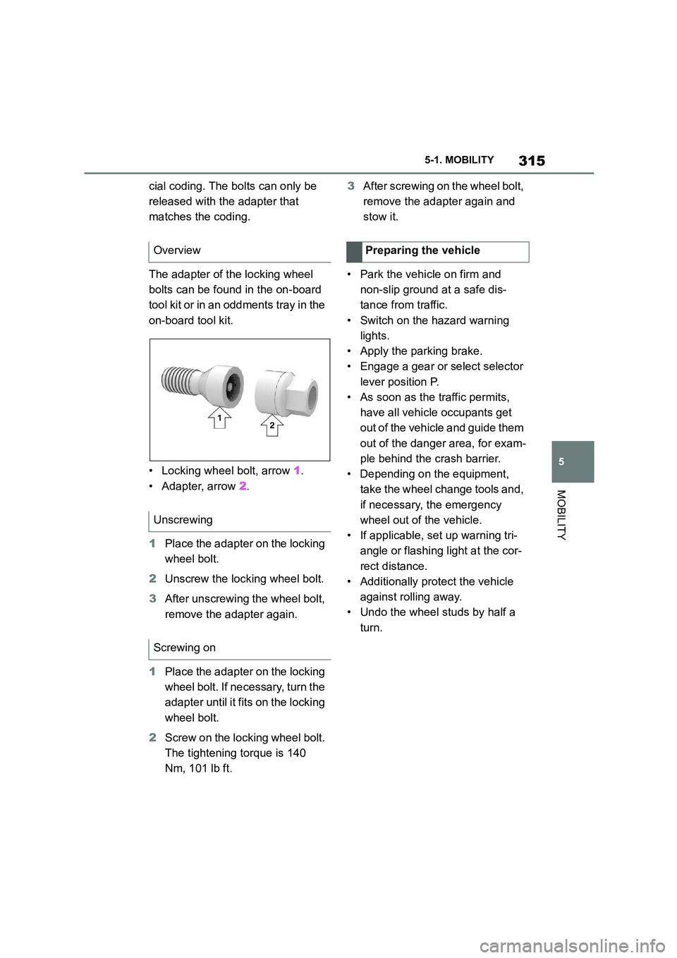
• Locking wheel bolt, arrow 1.
• Adapter, arrow 2.
1 Place the adapter on the locking
wheel bolt.
2 Unscrew the locking wheel bolt.
3 After unscrewing the wheel bolt,
remove the adapter again.
1 Place the adapter on the locking
wheel bolt. If necessary, turn the
adapter until it fi ts on the locking
wheel bolt.
2 Screw on the locking wheel bolt.
The tightening torque is 140
Nm, 101 lb ft.
3 After screwing on the wheel bolt,
remove the adapter again and
stow it.
• Park the vehicle on firm and
non-slip ground at a safe dis-
tance from traffic.
• Switch on the hazard warning
lights.
• Apply the parking brake.
• Engage a gear or select selector
lever position P.
• As soon as the traffic permits,
have all vehicle occupants get
out of the vehicle and guide them
out of the danger area, for exam-
ple behind the crash barrier.
• Depending on the equipment,
take the wheel change tools and,
if necessary, the emergency
wheel out of the vehicle.
• If applicable, set up warning tri-
angle or flashing light at the cor-
rect distance.
• Additionally protect the vehicle
against rolling away.
• Undo the wheel studs by half a
turn.
Overview
Unscrewing
Screwing on
Preparing the vehicle
Page 332 of 498

3305-1. MOBILITY
This chapter describes all standard,
country-specific and special equip-
ment available for the model series.
It may therefore describe equip-
ment and functions which are not
installed in your vehicle, for exam-
ple on account of the special equip-
ment selected or the country
specification. This also applies to
safety-relevant functions and sys-
tems. Please comply with the rele-
vant laws and regulations when
using the corresponding functions
and systems.
The maintenance system indicates
what maintenance measures are
required and thereby assists in
maintaining the road safety and
operational safety of the vehicle.
The exact work required and the
maintenance intervals may vary
depending on the country specifica-
tions. Replacement work, spare
parts, operating materials and wear
materials are calculated sepa-
rately. Additional information is
available from a dealer of the man-
ufacturer or another qualified dealer
or a specialist workshop.
Condition Based Service CBS
determines the maintenance
requirement using sensors and
special algorithms which monitor
the conditions in which the vehicle
is used.
The system thus enables the scope
of the maintenance work to be
adapted to the individual usage
profile.
Information on service require-
ments, see page 170, can be
shown on the Control Display.
Periods when the vehicle is out of
use with its battery disconnected
are not taken into account.
In such cases, have any
time-dependent maintenance pro-
cedures, for example for the brake
fluid and, where applicable, the
engine oil and microfilter/activated
charcoal filter, updated by a dealer
of the manufacturer or another
qualified dealer or a specialist
workshop.
Maintenance
Vehicle equipment
Maintenance System
Condition Based Service
CBS
Principle
General
Periods out of use
Page 334 of 498

3325-1. MOBILITY
maintenance on your vehicle reliably
and economically.
Rubber hoses (for cooling and heater
system, brake system and fuel system)
should be inspected by a qualified tech-
nician according to the Toyota mainte-
nance schedule.
Rubber hoses are particularly important
maintenance items. Have any deterio-
rated or damaged hoses replaced
immediately. Note that rubber hoses
will deteriorate with age, resulting in
swelling, chafing or cracking.
No maintenance work other than
normal maintenance is required to
keep the emission levels of your
vehicle within the design limits.
Devices connected to the OBD
socket trigger the alarm system
when the vehicle is locked.
Remove any devices connected to
the OBD socket before locking the
vehicle.
The OBD socket for checking emis-
sions-relevant components is
located on the driver's side.
For Australia: maintenance
Socket for on-board diagno-
sis OBD
General
Safety note
NOTICE
Incorrect use of the OBD on-board
diagnosis socket can result in mal- functions in the vehicle. There is a
danger of damage to property. Only
have service and maintenance work involving the OBD on-board diagnosis
socket carried out by any authorized
Toyota retailer or Toyota authorized
repairer, or any reliable repairer or other authorised persons. Only con-
nect devices that have been tested
and found to be safe for use with the OBD on-board diagnosis socket.
Position
Page 336 of 498
3345-1. MOBILITY
Your vehicle needs to be serviced according to the normal maintenance
schedule.
Maintenance operations:
I = Inspect, correct or replace as necessary
R = Replace, change or lubricate
Scheduled maintenance (except for Europe and
Australia)
Perform maintenance by the schedule as follows:
Maintenance schedule requirements
Maintenance schedule (except for Korea, Mexico and South
Africa)
SERVICE
INTERVAL:ODOMETER READING
MONTHS(Odometer
reading or
months, which-
ever comes
first.)
x1000
km1224364860728496
x1000
miles7.214.421.628.83643.250.457.6
BASIC ENGINE COMPONENTS
1
Engine oil (Include
engine oil filter)
<>
RRRRRRRR12
IGNITION SYSTEM
2Spark plugsRRRR24
FUEL AND EMISSION CONTROL SYSTEMS
3Air filterRRRR24
CHASSIS AND BODY
4Brake padsReplace when the brake warning light
appears.-
5Brake fluidFirst replace at 36 months, then replace at every 24
months.
Page 337 of 498
335
5
5-1. MOBILITY
MOBILITY
6
Horn, headlight flash-
ers and hazard warn-
ing flashers
II48
7Interior lightingII48
8BlowerII48
9Lighting systemII48
10Seat beltsII48
11Wiper and window
washer systemII48
12
Tire settings in the
central information
display (CID)
II48
13Tires (If necessary,
emergency wheel)II48
14Mobility SetII48
15
Warning triangle,
high-visibility jacket
and first-aid kit
II48
16
Washer fluid for the
window washer sys-
tem
II48
17Coolant level and
coolant compositionII48
18
Brake lines and the
brake line connec-
tions
II48
19
Vehicle underbody
and all other visible
components
II48
20Steering componentsII48
SERVICE
INTERVAL:ODOMETER READING
MONTHS(Odometer
reading or
months, which-
ever comes
first.)
x1000
km1224364860728496
x1000
miles7.214.421.628.83643.250.457.6
Page 339 of 498
337
5
5-1. MOBILITY
MOBILITY
4Brake padsReplace when the brake warning light
appears.-
5Brake fluidFirst replace at 36 months, then replace at every 24
months.
6
Horn, headlight flash-
ers and hazard warn-
ing flashers
II36
7Interior lightingII36
8BlowerII36
9Lighting systemII36
10Seat beltsII36
11Wiper and window
washer systemII36
12
Tire settings in the
central information
display (CID)
II36
13Tires (If necessary,
emergency wheel)II36
14Mobility SetII36
15
Warning triangle,
high-visibility jacket
and first-aid kit
II36
16
Washer fluid for the
window washer sys-
tem
II36
17Coolant level and
coolant compositionII36
18Brake lines and the
brake line connectionsII36
SERVICE INTER-
VA L :ODOMETER READING
MONTHS(Odometer read-
ing or months,
whichever comes
first.)
x1000
km20406080100120
x1000
miles122436486072