Page 65 of 260

STARTING AND OPERATING63
PARKSENSE REAR PARK ASSIST
A
LERTS
If an obstacle is behind the vehicle when REVERSE gear is engaged, an audible alert is activated.
The tones emitted by the loudspeaker inform the driver that the vehicle is approaching an obstacle. The pauses between the tones are directly proportional to
the distance from the obstacle. Pulses emitted in quick succession indicate the presence of a very close obstacle. A continuous tone indicates that the obstacle
is less than 12 inches (30 cm) away.
While audible signals are emitted, the audio system is muted.
The audible signal is turned off immediately if the distance increases. The tone cycle remains constant if the distance measured by the inner sensors is constant.
If this condition occurs for the external sensors, the signal is turned off after three seconds (stopping warnings during maneuvers parallel to walls).
Audible And Visual Signals Supplied By The Park Assist System
SIGNAL MEANING INDICATION
Obstacle Distance
An obstacle is present within the sensors' field of view
Audible signal
(dashboard loudspeaker)
• Sound pulses emitted at a rate that increases as
the distance decreases
• Emits continuous tone at 12 inches (30 cm)
• Adjustable volume level programmable through
personal settings in the instrument cluster display
Ú page 40
Failure Sensor or system failuresVisual Signal
(instrument panel)
• Icon appears on display
• Message is displayed on instrument cluster
display (if equipped)4
22_VM_OM_EN_USC_t.book Page 63
Page 66 of 260

64STARTING AND OPERATING
PARKSENSE REAR PARK ASSIST
F
AILURE INDICATIONS
A malfunction of the ParkSense sensors
or system is indicated, during REVERSE
gear engagement, by the instrument
panel warning icon.
The warning icon is illuminated and a message is
displayed on the instrument cluster display (if
equipped) Ú page 44.
The sensors and wiring are tested continuously
when the ignition is in the MAR (ACC/ON/RUN)
position. Failures are indicated immediately if they
occur when the system is on.
Even if the system is able to identify that a specific
sensor is in failure condition, the instrument
cluster display shall indicate that the ParkSense
system is unavailable, without reference to the
sensor in failure condition. If even a single sensor
fails, the entire system will be disabled. The system
is turned off automatically.
CLEANING THE PARKSENSE REAR PARK
A
SSIST SYSTEM
Clean the ParkSense sensors with water, car wash
soap and a soft cloth. Do not use rough or hard
cloths. In washing stations, clean sensors quickly
while keeping the vapor jet/high pressure washing
nozzles at least 4 inches (10 cm) from the sensors. Do not scratch or poke the sensors. Otherwise, you
could damage the sensors.
PARKSENSE REAR PARK ASSIST
S
YSTEM USAGE PRECAUTIONS
NOTE:
Ensure that the outer surface and the underside
of the rear fascia/bumper is clean and clear of
snow, ice, mud, dirt or other obstruction to keep
the ParkSense Rear Park Assist system oper -
ating properly.
Jackhammers, large trucks, and other vibra -
tions could affect the performance of the
ParkSense system.
Clean the ParkSense sensors regularly, taking
care not to scratch or damage them. The sensors
must not be covered with ice, snow, slush, mud,
dirt or debris. Failure to do so can result in the
system not working properly. The ParkSense
system might not detect an obstacle behind the
fascia/bumper, or it could provide a false indica -
tion that an obstacle is behind the fascia/bumper.
Objects such as bicycle carriers, etc., must not
be placed within 12 inches (30 cm) from the
rear fascia/bumper while driving the vehicle.
Failure to do so can result in the system misin -
terpreting a close object as a sensor problem,
causing a failure indication to be displayed in
the instrument cluster display.
WARNING!
Drivers must be careful when backing up even
when using ParkSense. Always check carefully
behind your vehicle, look behind you, and be
sure to check for pedestrians, animals, other
vehicles, obstructions, and blind spots before
backing up. You are responsible for safety and
must continue to pay attention to your
surroundings. Failure to do so can result in
serious injury or death.
Before using ParkSense, it is strongly recom -
mended that the ball mount and hitch ball
assembly be disconnected from the vehicle
when the vehicle is not used for towing.
Failure to do so can result in injury or damage
to vehicles or obstacles because the hitch
ball will be much closer to the obstacle than
the rear fascia when the vehicle sounds the
continuous tone. Also, the sensors could
detect the ball mount and hitch ball
assembly, depending on its size and shape,
giving a false indication that an obstacle is
behind the vehicle.
22_VM_OM_EN_USC_t.book Page 64
Page 67 of 260

STARTING AND OPERATING65
If it’s necessary to keep the ball mount and hitch
ball assembly mounted for a long period, it is
possible to filter out the ball mount and hitch ball
assembly presence in the sensor field of view. The
filtering operation must be performed only by an
authorized dealer.
PARKVIEW REAR BACK UP CAMERA
Your vehicle is equipped with the ParkView Rear
Back Up Camera that allows you to see an
on-screen image of the rear surroundings of your
vehicle whenever the gear selector is put into
REVERSE. The image will be displayed on the
touchscreen display along with a caution note to “Check Entire Surroundings” across the top of the
screen. After five seconds this note will disappear.
The ParkView camera is located on the rear of the
vehicle above the rear license plate.
The Rear Back Up Camera can also be activated
when the vehicle is not in REVERSE through the
Uconnect system Ú
page 79.
NOTE:If one of the rear cargo doors is not completely
closed, the Back Up Camera cannot provide an
accurate image of the area behind the vehicle. A
dedicated message will appear on the Uconnect
display indicating the camera is not in the correct
position.
The Camera Delay setting can be set to on/off in
the rear camera settings menu. When the vehicle
is shifted out of REVERSE and the Camera Delay is
turned off, the rear camera mode is exited and the
navigation or audio screen appears on display
again.
When the transmission is shifted out of REVERSE,
and Camera Delay is activated in the menu screen,
the camera image will continue to be displayed for
up to 10 seconds, unless the speed of the vehicle
is greater than 8 mph (13 km/h), the transmission
is in PARK, or the ignition is placed in the STOP
(OFF/LOCK) position. When displayed, static grid lines will illustrate the
width of the vehicle and will show separate zones
that will help indicate the distance to the rear of
the vehicle. The following table shows the
approximate distances for each zone:
CAUTION!
ParkSense is only a parking aid and it is
unable to recognize every obstacle, including
small obstacles. Parking curbs might be
temporarily detected or not detected at all.
Obstacles located above or below the sensors
will not be detected when they are in close
proximity.
The vehicle must be driven slowly when using
ParkSense in order to be able to stop in time
when an obstacle is detected. It is recom
-
mended that the driver looks over his/her
shoulder when using ParkSense.
Zone Distance To The Rear
Of The Vehicle
Red 0 - 1 ft (0 - 30 cm)
Yellow 1 ft - 3 ft (30 cm - 1 m)
Green 3 ft or greater
(1 m or greater)
WARNING!
Drivers must be careful when backing up even
when using the ParkView Rear Back Up Camera.
Always check carefully behind your vehicle, and
be sure to check for pedestrians, animals, other
vehicles, obstructions, or blind spots before
backing up. You are responsible for the safety of
your surroundings and must continue to pay
attention while backing up. Failure to do so can
result in serious injury or death.
4
22_VM_OM_EN_USC_t.book Page 65
Page 68 of 260

66STARTING AND OPERATING
NOTE:If snow, ice, mud, or any foreign substance builds
up on the camera lens, clean the lens, rinse with
water, and dry with a soft cloth. Do not cover the
lens.
REFUELING THE VEHICLE
The gas cap is located on the left side of the
vehicle. If the gas cap is lost or damaged, be sure
to use the correct replacement cap for this vehicle
1. Open the fuel filler door.
2. Remove the fuel cap by rotating it counter -
clockwise.
Fuel Filler Cap
NOTE:The driver's side sliding door cannot be opened
while the fuel door is open. This feature operates
only when the sliding door is in a closed position
prior to opening the fuel door.
3. Fully insert the gasoline nozzle into the filler
pipe.
4. Fill the vehicle with fuel.
NOTE:
When the fuel nozzle “clicks” or shuts off,
the fuel tank is full.
Wait five seconds before removing the fuel
nozzle to allow excess fuel to drain from the
nozzle.
5. Remove gasoline nozzle, reinstall fuel cap and close fuel filler door.
CAUTION!
To avoid vehicle damage, ParkView should
only be used as a parking aid. The ParkView
camera is unable to view every obstacle or
object in your drive path.
To avoid vehicle damage, the vehicle must be
driven slowly when using ParkView to be able
to stop in time when an obstacle is seen. It is
recommended that the driver look frequently
over his/her shoulder when using ParkView.
WARNING!
Never have any smoking materials lit in or
near the vehicle when the gas cap is removed
or the tank is being filled.
Never add fuel when the engine is running.
This is in violation of most state and federal
fire regulations and may cause the Malfunc -
tion Indicator Light (MIL) to turn on.
A fire may result if gasoline is pumped into a
portable container that is inside of a vehicle.
You could be burned. Always place gas
containers on the ground while filling.
CAUTION!
Damage to the fuel system or emissions
control system could result from using an
improper fuel tank filler tube cap. A poorly
fitting cap could let impurities into the fuel
system and may cause the Malfunction Indi -
cator Light (MIL) to turn on, due to fuel vapors
escaping from the system.
To avoid fuel spillage and overfilling, do not
“top off” the fuel tank after filling.
22_VM_OM_EN_USC_t.book Page 66
Page 69 of 260

STARTING AND OPERATING67
NOTE:
Tighten the fuel filler cap until you hear a
“clicking” sound. This is an indication that the
fuel filler cap is properly tightened.
If the gas cap is not tightened properly, the MIL
may come on. Be sure the gas cap is tightened
every time the vehicle is refueled.
VEHICLE LOADING
As required by National Highway Traffic Safety
Administration regulations, your vehicle has a
certification label affixed to the driver's side door or
B-pillar.
If seats are removed for carrying cargo, do not
exceed the specified GVWR and GAWR.
VEHICLE CERTIFICATION LABEL
Your vehicle has a Vehicle Certification Label
affixed to the driver’s side B-pillar or the rear of the
driver’s door.
The label contains the following information:
Name of manufacturer
Month and year of manufacture
Gross Vehicle Weight Rating (GVWR)
Gross Axle Weight Rating (GAWR) front and rear
Vehicle Identification Number (VIN)
Type of vehicle
Month, Day, and Hour of manufacture (MDH)
The bar code allows a computer scanner to read
the VIN.
GROSS VEHICLE WEIGHT RATING
(GVWR)
The GVWR is the total allowable weight of your
vehicle. This includes driver, passengers, and
cargo. The total load must be limited so that you do
not exceed the GVWR.
GROSS AXLE WEIGHT RATING (GAWR)
The GAWR is the maximum capacity of the front
and rear axles. Distribute the load over the front
and rear axles evenly. Make sure that you do not
exceed either front or rear GAWR.
TIRE SIZE
The tire size on the Vehicle Certification Label
represents the actual tire size on your vehicle.
Replacement tires must be equal to the load
capacity of this tire size.
RIM SIZE
This is the rim size that is appropriate for the tire
size listed.
INFLATION PRESSURE
This is the cold tire inflation pressure for your
vehicle for all loading conditions up to full GAWR.
CURB WEIGHT
The curb weight of a vehicle is defined as the total
weight of the vehicle with all fluids, including
vehicle fuel, at full capacity conditions, and with no
occupants or cargo loaded into the vehicle. The
front and rear curb weight values are determined
by weighing your vehicle on a commercial scale
before any occupants or cargo are added.
WARNING!
Because the front wheels steer the vehicle, it is
important that you do not exceed the maximum
front or rear GAWR. A dangerous driving
condition can result if either rating is exceeded.
You could lose control of the vehicle and have a
collision.
4
22_VM_OM_EN_USC_t.book Page 67
Page 70 of 260
 of your vehicle will provide
satisfactory service as long as you do not exceed
the GVWR and")
68STARTING AND OPERATING
OVERLOADING
The load carrying components (axle, springs, tires,
wheels, etc.) of your vehicle will provide
satisfactory service as long as you do not exceed
the GVWR and the front and rear GAWR.
The best way to figure out the total weight of your
vehicle is to weigh it when it is fully loaded and
ready for operation. Weigh it on a commercial scale
to ensure that it is not over the GVWR.
Figure out the weight on the front and rear of the
vehicle separately. It is important that you distribute
the load evenly over the front and rear axles.
Overloading can cause potential safety hazards
and shorten useful service life. Heavier axles or
suspension components do not necessarily
increase the vehicle's GVWR.
LOADING
To load your vehicle properly, first figure out its
empty weight, axle-by-axle and side-by-side. Store
heavier items down low and be sure you distribute
their weight as evenly as possible. Stow all loose
items securely before driving. If weighing the
loaded vehicle shows that you have exceeded
either GAWR, but the total load is within the
specified GVWR, you must redistribute the weight.
Improper weight distribution can have an adverse
effect on the way your vehicle steers and handles
and the way the brakes operate.
NOTE:Refer to the “Vehicle Certification Label” affixed to
the B-pillar or the rear of the driver's door for your
vehicle's GVWR and GAWR.
TRAILER TOWING
In this section you will find safety tips and
information on limits to the type of towing you can
reasonably do with your vehicle. Before towing a
trailer, carefully review this information to tow your
load as efficiently and safely as possible.
To maintain the New Vehicle Limited Warranty
coverage, follow the requirements and
recommendations in this manual concerning
vehicles used for trailer towing.
COMMON TOWING DEFINITIONS
The following trailer towing related definitions will
assist you in understanding the following
information:
Gross Vehicle Weight Rating (GVWR)
The GVWR is the total allowable weight of your
vehicle. This includes driver, passengers, cargo
and tongue weight. The total load must be limited
so that you do not exceed the GVWR Ú page 67.
Gross Combination Weight Rating (GCWR)
The GCWR is the total allowable weight of your
vehicle and trailer when weighed in combination.
Gross Trailer Weight (GTW)
The GTW is the weight of the trailer plus the weight
of all cargo, consumables and equipment
(permanent or temporary) loaded in or on the
trailer in its "loaded and ready for operation"
condition.
The recommended way to measure GTW is to put
your fully loaded trailer on a vehicle scale. The
entire weight of the trailer must be supported by
the scale.
Gross Axle Weight Rating (GAWR)
The GAWR is the maximum capacity of the front
and rear axles. Distribute the load over the front
and rear axles evenly. Make sure that you do not
exceed either front or rear GAWR Úpage 67.
WARNING!
It is important that you do not exceed the
maximum front or rear GAWR. A dangerous
driving condition can result if either rating is
exceeded. You could lose control of the vehicle
and have a collision.
22_VM_OM_EN_USC_t.book Page 68
Page 71 of 260

The TW is the downward force exerted on the hitch
ball by the trailer. You must consider this as part of
the load on your vehicle.
Trailer Frontal Area
T")
STARTING AND OPERATING69
Tongue Weight (TW)
The TW is the downward force exerted on the hitch
ball by the trailer. You must consider this as part of
the load on your vehicle.
Trailer Frontal Area
The frontal area is the maximum height multiplied
by the maximum width of the front of a trailer.
Trailer Sway Control (TSC)
The TSC can be a mechanical telescoping link that
can be installed between the hitch receiver and the
trailer tongue that typically provides adjustable
friction associated with the telescoping motion to
dampen any unwanted trailer swaying motions
while traveling.
If equipped, the electronic TSC recognizes a
swaying trailer and automatically applies individual
wheel brakes and/or reduces engine power to
attempt to eliminate the trailer sway.
Weight-Carrying Hitch
A weight-carrying hitch supports the trailer tongue
weight, just as if it were luggage located at a hitch
ball or some other connecting point of the vehicle.
These kinds of hitches are commonly used to tow
small and medium sized trailers.
Weight-Distributing Hitch
The weight-distributing hitch works by applying
leverage through spring (load) bars. They are
typically used for heavier loads to distribute trailer
tongue weight to the tow vehicle's front axle and
the trailer axle(s). When used in accordance with
the manufacturer's directions, it provides for a
more level ride, offering more consistent steering
and brake control thereby enhancing towing
safety. The addition of a friction/hydraulic sway
control also dampens sway caused by traffic and
crosswinds and contributes positively to tow vehicle and trailer stability. Trailer Sway Control
(TSC) and a weight distributing (load equalizing)
hitch are recommended for heavier Tongue
Weights (TW) and may be required depending on
vehicle and trailer configuration/loading to comply
with Gross Axle Weight Rating (GAWR)
requirements.WARNING!
An improperly adjusted Weight Distributing
Hitch system may reduce handling, stability,
braking performance, and could result in a
collision.
Weight Distributing Systems may not be
compatible with Surge Brake Couplers.
Consult with your hitch and trailer manufac-
turer or a reputable Recreational Vehicle
dealer for additional information.
4
22_VM_OM_EN_USC_t.book Page 69
Page 72 of 260
70STARTING AND OPERATING
TRAILER HITCH CLASSIFICATION
The following chart provides the industry standard for the maximum trailer weight a given trailer hitch class can tow and should be used to assist you in selecting
the correct trailer hitch for your intended towing condition.
Trailer Hitch Classification Definitions
Class Max. Trailer Hitch Industry Standards
Class I - Light Duty 2,000 lb (907 kg)
Class II - Medium Duty 3,500 lb (1,587 kg)
Class III - Heavy Duty 6,000 lb (2,721 kg)
Class IV - Extra Heavy Duty 10,000 lb (4,535 kg)
See chart on Ú page 71 for the Maximum Gross Trailer Weight (GTW) towable for your given drivetrain.
All trailer hitches should be professionally installed on your vehicle.
22_VM_OM_EN_USC_t.book Page 70
 1
1 2
2 3
3 4
4 5
5 6
6 7
7 8
8 9
9 10
10 11
11 12
12 13
13 14
14 15
15 16
16 17
17 18
18 19
19 20
20 21
21 22
22 23
23 24
24 25
25 26
26 27
27 28
28 29
29 30
30 31
31 32
32 33
33 34
34 35
35 36
36 37
37 38
38 39
39 40
40 41
41 42
42 43
43 44
44 45
45 46
46 47
47 48
48 49
49 50
50 51
51 52
52 53
53 54
54 55
55 56
56 57
57 58
58 59
59 60
60 61
61 62
62 63
63 64
64 65
65 66
66 67
67 68
68 69
69 70
70 71
71 72
72 73
73 74
74 75
75 76
76 77
77 78
78 79
79 80
80 81
81 82
82 83
83 84
84 85
85 86
86 87
87 88
88 89
89 90
90 91
91 92
92 93
93 94
94 95
95 96
96 97
97 98
98 99
99 100
100 101
101 102
102 103
103 104
104 105
105 106
106 107
107 108
108 109
109 110
110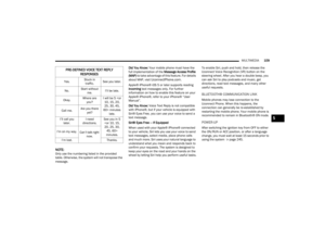 111
111 112
112 113
113 114
114 115
115 116
116 117
117 118
118 119
119 120
120 121
121 122
122 123
123 124
124 125
125 126
126 127
127 128
128 129
129 130
130 131
131 132
132 133
133 134
134 135
135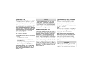 136
136 137
137 138
138 139
139 140
140 141
141 142
142 143
143 144
144 145
145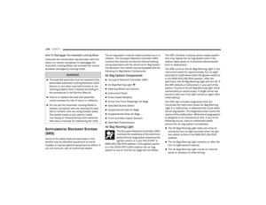 146
146 147
147 148
148 149
149 150
150 151
151 152
152 153
153 154
154 155
155 156
156 157
157 158
158 159
159 160
160 161
161 162
162 163
163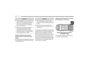 164
164 165
165 166
166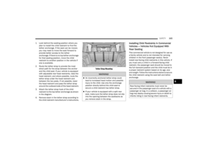 167
167 168
168 169
169 170
170 171
171 172
172 173
173 174
174 175
175 176
176 177
177 178
178 179
179 180
180 181
181 182
182 183
183 184
184 185
185 186
186 187
187 188
188 189
189 190
190 191
191 192
192 193
193 194
194 195
195 196
196 197
197 198
198 199
199 200
200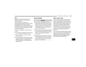 201
201 202
202 203
203 204
204 205
205 206
206 207
207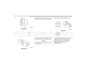 208
208 209
209 210
210 211
211 212
212 213
213 214
214 215
215 216
216 217
217 218
218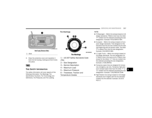 219
219 220
220 221
221 222
222 223
223 224
224 225
225 226
226 227
227 228
228 229
229 230
230 231
231 232
232 233
233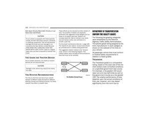 234
234 235
235 236
236 237
237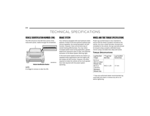 238
238 239
239 240
240 241
241 242
242 243
243 244
244 245
245 246
246 247
247 248
248 249
249 250
250 251
251 252
252 253
253 254
254 255
255 256
256 257
257 258
258 259
259