2022 RAM PROMASTER CITY warning light
[x] Cancel search: warning lightPage 5 of 260

3
TRIP COMPUTER .................................................... 43 Trip Button ........................................................43
Trip Functions ..................................................43
Values Displayed ..............................................44
WARNING LIGHTS AND MESSAGES ................... 44
Red Warning Lights ..........................................44
Yellow Warning Lights ......................................47
Green Indicator Lights......................................49
Blue Indicator Lights ........................................50
White Indicator Lights ......................................50
ONBOARD DIAGNOSTIC SYSTEM — OBD II ....... 50
Onboard Diagnostic System
(OBD II) Cybersecurity ......................................51
EMISSIONS INSPECTION AND MAINTENANCE
PROGRAMS ............................................................ 51
STARTING AND OPERATING
STARTING THE ENGINE ........................................ 52
Automatic Transmission ..................................52
Normal Starting ................................................52
Cold Weather Operation .................................52
Extended Park Starting ....................................52
If Engine Fails To Start .....................................53
After Starting.....................................................53
ENGINE BLOCK HEATER — IF EQUIPPED ............ 53
ENGINE BREAK-IN RECOMMENDATIONS .......... 54
PARKING BRAKE .................................................. 54 AUTOMATIC TRANSMISSION ...............................55
Key Ignition Park Interlock...............................56
Brake/Transmission Shift Interlock (BTSI)
System .............................................................56
9-Speed Automatic Transmission ..................56
POWER STEERING ................................................60
Power Steering Fluid Check ............................60
CRUISE CONTROL — IF EQUIPPED .......................60
To Activate ........................................................61
To Set A Desired Speed ...................................61
To Vary The Speed Setting...............................61
To Accelerate For Passing ...............................61
To Resume Speed ............................................62
To Deactivate ...................................................62
PARKSENSE REAR PARK ASSIST —
IF EQUIPPED ...........................................................62
ParkSense Rear Park Assist Sensors .............62
ParkSense Rear Park Assist Alerts .................63
ParkSense Rear Park Assist Failure
Indications ........................................................64
Cleaning The ParkSense Rear Park Assist
System ..............................................................64
ParkSense Rear Park Assist System Usage
Precautions.......................................................64
PARKVIEW REAR BACK UP CAMERA .................65
REFUELING THE VEHICLE .....................................66 VEHICLE LOADING ................................................. 67
Vehicle Certification Label............................... 67
Gross Vehicle Weight Rating (GVWR) ............. 67
Gross Axle Weight Rating (GAWR) .................. 67
Tire Size ............................................................ 67
Rim Size ............................................................ 67
Inflation Pressure ............................................. 67
Curb Weight ...................................................... 67
Overloading ...................................................... 68
Loading ............................................................ 68
TRAILER TOWING .................................................. 68
Common Towing Definitions............................ 68
Trailer Hitch Classification............................... 70
Trailer Towing Weights (Maximum Trailer
Weight Ratings) ............................................... 71
Trailer And Tongue Weight .............................71
Towing Requirements ..................................... 71
Towing Tips ...................................................... 74
RECREATIONAL TOWING
(BEHIND MOTORHOME) ....................................... 75
Towing This Vehicle Behind Another Vehicle .... 75
Recreational Towing — Automatic Transmission .. 76
DRIVING TIPS ......................................................... 76
Driving On Slippery Surfaces .......................... 76
Driving Through Water ....................................76
22_VM_OM_EN_USC_t.book Page 3
Page 10 of 260
8
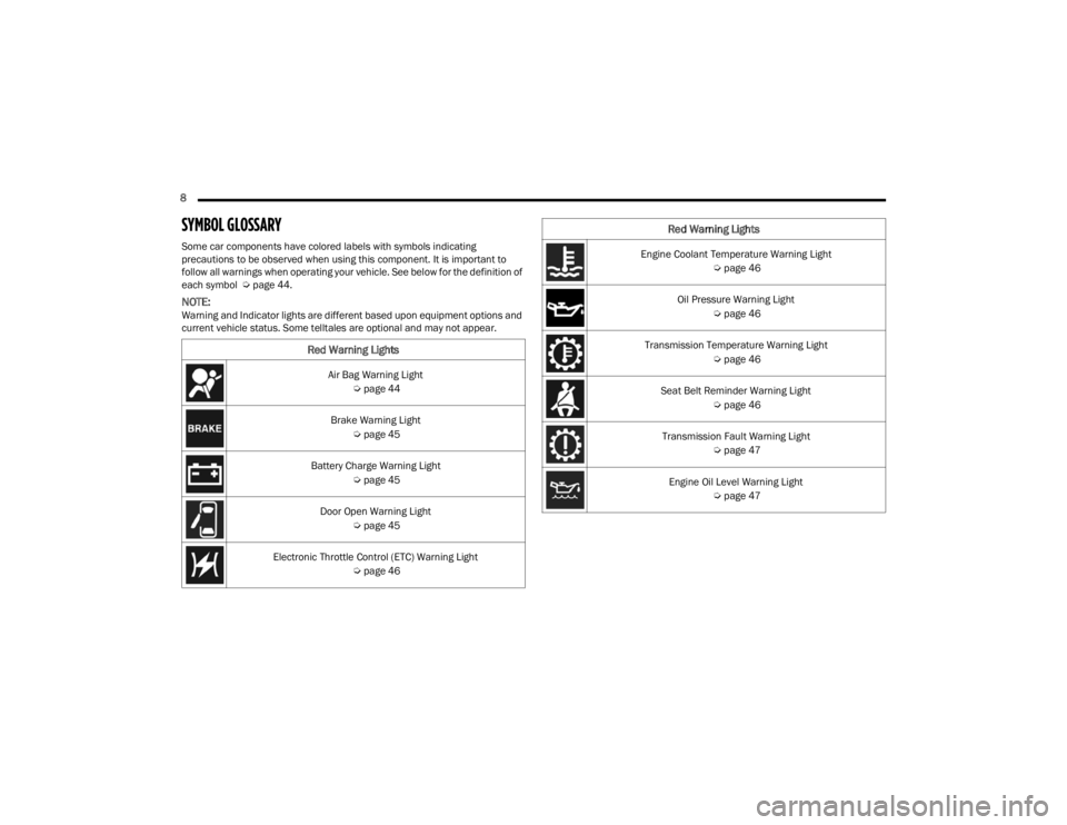
SYMBOL GLOSSARY
Some car components have colored labels with symbols indicating
precautions to be observed when using this component. It is important to
follow all warnings when operating your vehicle. See below for the definition of
each symbol Úpage 44.
NOTE:Warning and Indicator lights are different based upon equipment options and
current vehicle status. Some telltales are optional and may not appear.
Red Warning Lights
Air Bag Warning Light
Úpage 44
Brake Warning Light Úpage 45
Battery Charge Warning Light Úpage 45
Door Open Warning Light Úpage 45
Electronic Throttle Control (ETC) Warning Light Úpage 46
Engine Coolant Temperature Warning Light
Úpage 46
Oil Pressure Warning Light Úpage 46
Transmission Temperature Warning Light Úpage 46
Seat Belt Reminder Warning Light Úpage 46
Transmission Fault Warning Light Úpage 47
Engine Oil Level Warning Light Úpage 47
Red Warning Lights
22_VM_OM_EN_USC_t.book Page 8
Page 11 of 260

9
Yellow Warning Lights
Anti-Lock Brake System (ABS) Warning Light Úpage 47
Low Fuel Warning Light Úpage 47
Generic Warning Light Úpage 47
Tire Pressure Monitoring System (TPMS) Warning Light Úpage 47
Vehicle Security Warning Light Úpage 48
Engine Check/Malfunction Indicator Warning Light (MIL) Úpage 48
Electronic Stability Control (ESC) Warning Light Úpage 49
Electronic Stability Control (ESC) OFF Warning Light Úpage 49
Green Indicator Lights
Turn Signal Indicator Lights
Úpage 49
Parking/Headlights On Indicator Light Úpage 49
Front Fog Indicator Light Úpage 49
Cruise Control Indicator Light Úpage 50
Blue Indicator Lights
High Beam Indicator Light
Úpage 50
White Indicator Lights
Speed Warning Indicator Light
Úpage 50
1
22_VM_OM_EN_USC_t.book Page 9
Page 14 of 260

12GETTING TO KNOW YOUR VEHICLE
SENTRY KEY
The Sentry Key Immobilizer system prevents
unauthorized vehicle operation by disabling the
engine. The system does not need to be armed or
activated. Operation is automatic, regardless of
whether the vehicle is locked or unlocked.
The system uses ignition keys which have an
embedded electronic chip (transponder) to
prevent unauthorized vehicle operation. Therefore,
only keys that are programmed to the vehicle can
be used to start and operate the vehicle.
If the Vehicle Security Light is on after the key is
placed in the MAR (ACC/ON/RUN) position, it
indicates that there is a problem with the
electronics.
All of the keys provided with your new vehicle have
been programmed to the vehicle electronics.
NOTE:A key which has not been programmed is also
considered an invalid key, even if it is cut to fit the
ignition switch lock cylinder for that vehicle
Úpage 245.
IGNITION SWITCH
1. Place the gear selector in PARK.
2. Rotate the key to the STOP (OFF/LOCK)
position.
3. Remove the key from the ignition switch lock cylinder.
Ignition Switch Positions
CAUTION!
The Sentry Key Immobilizer system is not
compatible with some aftermarket Remote
Starting systems. Use of these systems may
result in vehicle starting problems and loss of
security protection.
1 — AVV (START)
2 — MAR (ACC/ON/RUN)
3 — STOP (OFF/LOCK)
WARNING!
Before exiting a vehicle, always shift the trans -
mission into PARK, apply the parking brake, and
remove the key fob from the vehicle. When
leaving the vehicle, always lock your vehicle. In
case you switch off the vehicle and the transmis -
sion is not in PARK, a warning message will
appear on the cluster which indicates you to shift
the transmission into PARK and then you can
remove the key within 15 seconds. If 15 seconds
expire, you have to rotate the key from the STOP
(OFF/LOCK) position to the MAR (ACC/ON/RUN)
position and come back to the STOP (OFF/LOCK)
position in order to remove the key.
Never leave children alone in a vehicle, or with
access to an unlocked vehicle. Allowing chil -
dren to be in a vehicle unattended is dangerous
for a number of reasons. A child or others could
be seriously or fatally injured. Children should
be warned not to touch the parking brake,
brake pedal or the gear selector.
Do not leave the key fob in or near the vehicle,
or in a location accessible to children. A child
could operate power windows, other controls,
or move the vehicle.
Do not leave children or animals inside parked
vehicles in hot weather. Interior heat buildup
may cause serious injury or death.
22_VM_OM_EN_USC_t.book Page 12
Page 24 of 260
22GETTING TO KNOW YOUR VEHICLE
MIRRORS
INSIDE REARVIEW MIRROR
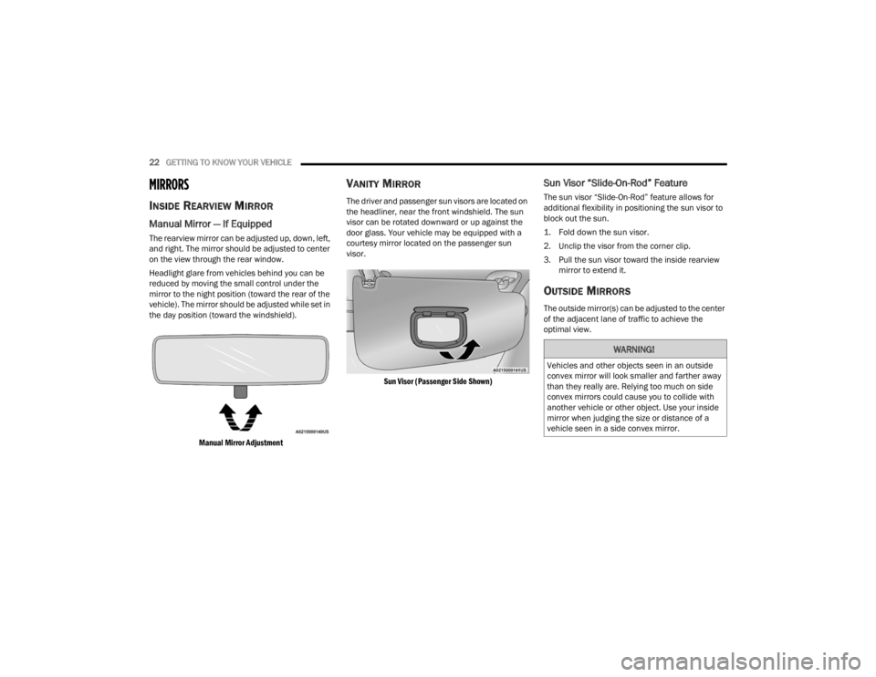
Manual Mirror — If Equipped
The rearview mirror can be adjusted up, down, left,
and right. The mirror should be adjusted to center
on the view through the rear window.
Headlight glare from vehicles behind you can be
reduced by moving the small control under the
mirror to the night position (toward the rear of the
vehicle). The mirror should be adjusted while set in
the day position (toward the windshield).
Manual Mirror Adjustment
VANITY MIRROR
The driver and passenger sun visors are located on
the headliner, near the front windshield. The sun
visor can be rotated downward or up against the
door glass. Your vehicle may be equipped with a
courtesy mirror located on the passenger sun
visor.
Sun Visor (Passenger Side Shown)
Sun Visor “Slide-On-Rod” Feature
The sun visor “Slide-On-Rod” feature allows for
additional flexibility in positioning the sun visor to
block out the sun.
1. Fold down the sun visor.
2. Unclip the visor from the corner clip.
3. Pull the sun visor toward the inside rearview mirror to extend it.
OUTSIDE MIRRORS
The outside mirror(s) can be adjusted to the center
of the adjacent lane of traffic to achieve the
optimal view.
WARNING!
Vehicles and other objects seen in an outside
convex mirror will look smaller and farther away
than they really are. Relying too much on side
convex mirrors could cause you to collide with
another vehicle or other object. Use your inside
mirror when judging the size or distance of a
vehicle seen in a side convex mirror.
22_VM_OM_EN_USC_t.book Page 22
Page 26 of 260
24GETTING TO KNOW YOUR VEHICLE
EXTERIOR LIGHTS
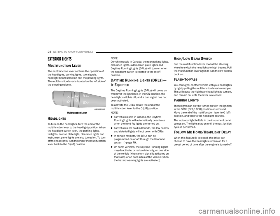
MULTIFUNCTION LEVER
The multifunction lever controls the operation of
the headlights, parking lights, turn signals,
headlight beam selection and the passing lights.
The multifunction lever is located on the left side of
the steering column.
Multifunction Lever
HEADLIGHTS
To turn on the headlights, turn the end of the
multifunction lever to the headlight position. When
the headlight switch is on, the parking lights,
taillights, license plate light, clearance lights and
instrument panel lights are also turned on. To turn
off the headlights, turn the end of the multifunction
lever back to the O (off) position.
NOTE:On vehicles sold in Canada, the rear parking lights,
clearance lights, sidemarker, plate lights and
Daytime Running Lights (DRLs) will turn on when
the headlight switch is rotated to the O (off)
position.
DAYTIME RUNNING LIGHTS (DRLS) —
I
F EQUIPPED
The Daytime Running Lights (DRLs) will come on
whenever the ignition is in the ON position, the
headlight switch is off, and a turn signal has not
been activated.
To activate the DRLs, rotate the end of the
multifunction lever to the O (off) position.
NOTE:
For vehicles sold in Canada, the Daytime
Running Lights will automatically deactivate
when the front fog lights are turned on.
For vehicles not sold in Canada, the low beams
and side/taillights will not be on with DRLs.
In certain markets, the DRLs can be
programmed on or off through the Uconnect
system Ú page 79.
On some vehicles, the Daytime Running Lights
may deactivate, or reduce intensity, on one side
of the vehicle (when a turn signal is activated on
that side), or on both sides of the vehicle (when
the hazard warning lights are activated).
HIGH/LOW BEAM SWITCH
Pull the multifunction lever toward the steering
wheel to switch the headlights to high beams. Pull
the multifunction lever again to turn the low beams
back on.
FLASH-TO-PASS
You can signal another vehicle with your headlights
by lightly pulling the multifunction lever toward you.
This will cause the high beam headlights to turn on,
and remain on, until the lever is released.
PARKING LIGHTS
These lights can only be turned on with the ignition
in the STOP (OFF/LOCK) position or removed.
Move the end of the multifunction lever to O (off)
position, and then to the headlight position.
The indicator light telltale in the instrument panel
comes on. The lights stay on until the next ignition
cycle is performed.
FOLLOW ME HOME/HEADLIGHT DELAY
When this feature is selected, the driver can
choose to have the headlights remain on for a
preset period of time after the engine is turned off.
22_VM_OM_EN_USC_t.book Page 24
Page 35 of 260
GETTING TO KNOW YOUR VEHICLE33
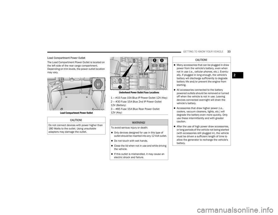
Load Compartment Power Outlet
The Load Compartment Power Outlet is located on
the left side of the rear cargo compartment.
Depending on trim levels, the power outlet location
may vary.
Load Compartment Power Outlet Underhood Power Outlet Fuse Locations
CAUTION!
Do not connect devices with power higher than
180 Watts to the outlet. Using unsuitable
adapters may damage the outlet.
1 — #15 Fuse 15A Blue IP Power Outlet 12V (Key)
2 — #30 Fuse 15A Blue 2nd IP Power Outlet
12V (Battery)
3 — #85 Fuse 15A Blue Rear Power Outlet
12V (Key)
WARNING!
To avoid serious injury or death:
Only devices designed for use in this type of
outlet should be inserted into any 12 Volt outlet.
Do not touch with wet hands.
Close the lid when not in use and while driving
the vehicle.
If this outlet is mishandled, it may cause an
electric shock and failure.
CAUTION!
Many accessories that can be plugged in draw
power from the vehicle's battery, even when
not in use (i.e., cellular phones, etc.). Eventu
-
ally, if plugged in long enough, the vehicle's
battery will discharge sufficiently to degrade
battery life and/or prevent the engine from
starting.
All accessories connected to the battery
powered outlets should be removed or turned
off when the vehicle is not in use. Leaving
devices connected overnight will drain the
vehicle’s battery.
Accessories that draw higher power (i.e.,
coolers, vacuum cleaners, lights, etc.) will
degrade the battery even more quickly. Only
use these intermittently and with greater
caution.
After the use of high power draw accessories,
or long periods of the vehicle not being started
(with accessories still plugged in), the vehicle
must be driven a sufficient length of time to
allow the generator to recharge the vehicle's
battery.
2
22_VM_OM_EN_USC_t.book Page 33
Page 37 of 260
GETTING TO KNOW YOUR VEHICLE35
Power Windows System Initialization
The power windows may be reset if any of the
following occurs:
On the front doors:
Fuse or battery are disconnected when the
window is moving
50 window movements without ever closing
the window
On the rear doors (in addition to the conditions
for the front doors):
Fuse or battery are disconnected when the
window is moving
The auto-reverse system is activated while
the window is moving and the door is
opening
50 window movements without ever closing
the window
One door opening with the window moving,
without ever closing the door
Three doors opening with the window in
motion. During these maneuvers, the upper
stop position is never reached Proceed as follows for initialization:
1. Completely close the driver's door window,
keeping the window switch pushed for at
least five seconds after the (upper) end of
travel position.
2. Proceed in the same way on the passenger's window switches.
Rear Window Lockout Switch — If Equipped
The window lockout switch on the driver's door trim
panel allows you to disable the window controls on
the rear passenger doors. To disable the window
controls, push and release the window lockout
button (the indicator light on the button will turn
on). To enable the window controls, push and
release the window lockout button again (the
indicator light on the button will turn off).
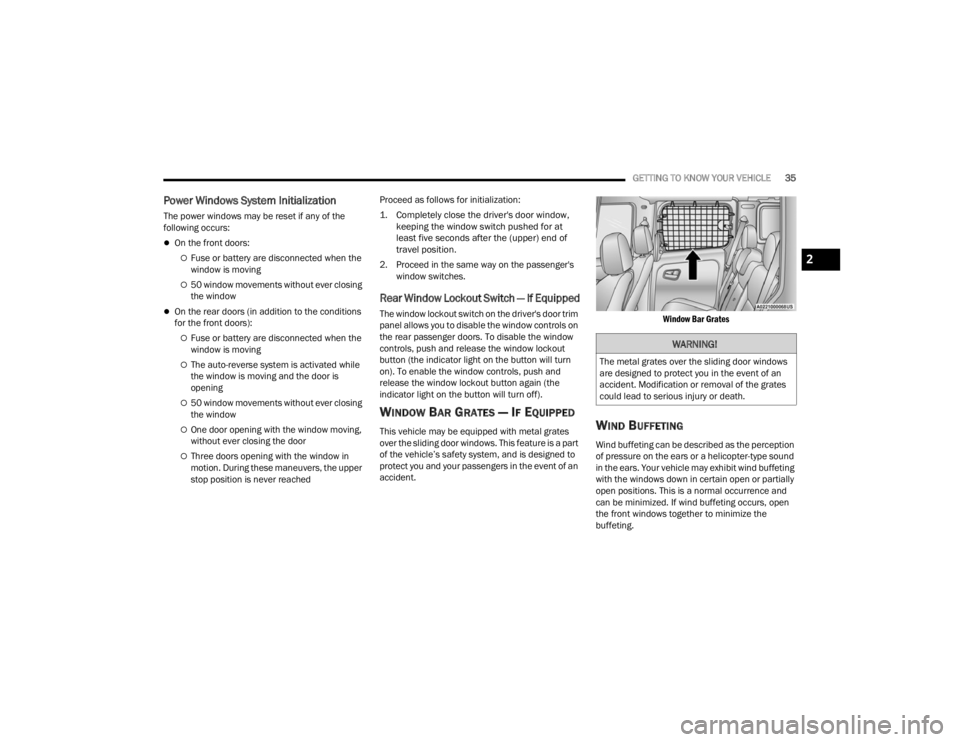
WINDOW BAR GRATES — IF EQUIPPED
This vehicle may be equipped with metal grates
over the sliding door windows. This feature is a part
of the vehicle’s safety system, and is designed to
protect you and your passengers in the event of an
accident.
Window Bar Grates
WIND BUFFETING
Wind buffeting can be described as the perception
of pressure on the ears or a helicopter-type sound
in the ears. Your vehicle may exhibit wind buffeting
with the windows down in certain open or partially
open positions. This is a normal occurrence and
can be minimized. If wind buffeting occurs, open
the front windows together to minimize the
buffeting.
WARNING!
The metal grates over the sliding door windows
are designed to protect you in the event of an
accident. Modification or removal of the grates
could lead to serious injury or death.
2
22_VM_OM_EN_USC_t.book Page 35