2022 RAM PROMASTER CITY ECO mode
[x] Cancel search: ECO modePage 6 of 260

4
MULTIMEDIA
UCONNECT SYSTEMS ........................................... 78
CYBERSECURITY ................................................... 78
UCONNECT SETTINGS .......................................... 79 Uconnect 3/3 NAV Settings .............................79
UCONNECT INTRODUCTION.................................. 88
Identifying Your Radio ......................................88
Safety And General Information ......................90
UCONNECT MODES ............................................... 91
Radio Mode ......................................................91
Media Mode......................................................98
Phone Mode ................................................. 100
NAVIGATION MODE — IF EQUIPPED ..................110
Operating Navigation Mode —If Equipped ... 110
STEERING WHEEL AUDIO CONTROLS —
IF EQUIPPED ........................................................ 128
Radio Operation ............................................ 128
Media Mode................................................... 129
RAM TELEMATICS - IF EQUIPPED ...................... 129
Ram Telematics General Information .......... 129
RADIO OPERATION AND MOBILE PHONES ..... 130
Regulatory And Safety Information .............. 130
SAFETY
SAFETY FEATURES .............................................. 131Four-Wheel Anti-Lock Brake System (ABS).. 131
Electronic Brake Control (EBC) System ...... 132
AUXILIARY DRIVING SYSTEMS.......................... 135
Tire Pressure Monitoring System (TPMS) .... 135
OCCUPANT RESTRAINT SYSTEMS ................... 137
Occupant Restraint Systems ........................ 137
Important Safety Precautions ...................... 137Seat Belt Systems ........................................ 138Supplemental Restraint Systems (SRS) ...... 144Child Restraints ............................................. 152
SAFETY TIPS ....................................................... 168
Transporting Passengers .............................. 168Transporting Pets ......................................... 168
Safety Checks You Should Make Inside
The Vehicle ................................................... 168
Periodic Safety Checks You Should Make
Outside The Vehicle ...................................... 169
Exhaust Gas................................................... 170
Carbon Monoxide Warnings ........................ 170
IN CASE OF EMERGENCY
HAZARD WARNING FLASHERS......................... 171
JACKING AND TIRE CHANGING ......................... 171
Preparations For Jacking ............................. 171
Jack Location — If Equipped ......................... 172
Removing The Spare Tire —If Equipped....... 172 Jacking Instructions ...................................... 174
Vehicles With Alloy Wheels ........................... 177
Vehicles Equipped With Wheel Covers ........ 178
TIRE SERVICE KIT — IF EQUIPPED .................... 179
Tire Service Kit Storage ................................ 179Tire Service Kit Usage ................................... 179
JUMP STARTING .................................................. 181
Preparations For Jump Starting ................... 181Jump Starting Procedure .............................. 182
IF YOUR ENGINE OVERHEATS ........................... 183
IGNITION KEY REMOVAL OVERRIDE ................. 184
GEAR SELECTOR OVERRIDE .............................. 184
FREEING A STUCK VEHICLE .............................. 185
TOWING A DISABLED VEHICLE .......................... 187
ENHANCED ACCIDENT RESPONSE SYSTEM
(EARS) .................................................................. 188
EVENT DATA RECORDER (EDR) ......................... 188
SERVICING AND MAINTENANCE
SCHEDULED SERVICING .................................... 189
Maintenance Plan ......................................... 190
ENGINE COMPARTMENT .................................... 193
Engine Compartment — 2.4L ....................... 193
Checking Oil Level ........................................ 194
Adding Washer Fluid .................................... 194
Maintenance-Free Battery ........................... 194
Pressure Washing ......................................... 195
22_VM_OM_EN_USC_t.book Page 4
Page 8 of 260

6
INTRODUCTION
Dear Customer,
Congratulations on selecting your new Ram. Be assured that it represents precision workmanship, distinctive styling, and high quality. This Owner’s Manual has
been prepared with the assistance of service and engineering specialists to acquaint you with the operation and maintenance of your vehicle. It is supplemented
by customer-oriented documents. Within this information, you will find a description of the services that FCA US LLC offers to its customers as well as the details
of the terms and conditions for maintaining its validity. Please take the time to read all of these publications carefully before driving your vehicle for the first time.
Following the instructions, recommendations, tips, and important warnings in this manual will help ensure safe and enjoyable operation of your vehicle. Be sure
you are familiar with all vehicle controls, particularly those used for braking, steering, transmission, and transfer case shifting (if equipped). Learn how your
vehicle handles on different road surfaces. Your driving skills will improve with experience.
This Owner’s Manual describes all versions of this vehicle. Options and equipment dedicated to specific markets or versions are not expressly indicated in
the text. Therefore, you should only consider the information that is related to the trim level, engine, and version that you have purchased. Any content
introduced throughout the Owner’s Information, which may or may not be applicable to your vehicle, will be identified with the wording “If Equipped”. All data
contained in this publication are intended to help you use your vehicle in the best possible way. FCA US LLC aims at a constant improvement of the vehicles
produced. For this reason, it reserves the right to make changes to the model described for technical and/or commercial reasons. For further information,
contact an authorized dealer.
When it comes to service, remember that authorized dealers know your Ram best, have factory-trained technicians and genuine Mopar® parts, and care about
your satisfaction.
22_VM_OM_EN_USC_t.book Page 6
Page 28 of 260

26GETTING TO KNOW YOUR VEHICLE
Rear Lights
Cargo Vehicle
Lateral Roof Light
This is located on the right side of the load
compartment.
Rear Roof Light
This is located on the rear panel of the load
compartment.
In auto-mode, the light comes on automatically
when you open the sliding doors and the rear swing
doors, and goes out when you close them.
Push the left-hand side of the lens to switch the
light off when the doors are open.
Push the right-hand side of the lens to switch
the light on when the doors are open.
Passenger Vehicle
The interior lamps are located in the center of the
roof, above the second row seating, and in the roof,
in the center of the rear load area. Second Row Seating And Rear Roof Lights
Operation
In auto-mode, the light comes on automatically
when you open the rear swing doors, and goes out
when you close them.
Push the left-hand side of the lens to switch the
light off when the doors are open.
Push the right-hand side of the lens to switch
the light on when the doors are open.
Cargo Compartment Light — If Equipped
The cargo compartment light comes on
automatically when the swing doors are opened
and turns off when the doors are closed.
WIPERS AND WASHERS
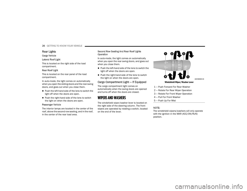
The windshield wiper/washer lever is located on
the right side of the steering column. The front
wipers are operated by rotating a switch, located
on the end of the lever.
Windshield Wiper/Washer Lever
NOTE:The windshield wipers/washers will only operate
with the ignition in the MAR (ACC/ON/RUN)
position.1 — Push Forward For Rear Washer
2 — Rotate For Rear Wiper Operation
3 — Rotate For Front Wiper Operation
4 — Pull For Front Washer
5 — Push Up For Mist
22_VM_OM_EN_USC_t.book Page 26
Page 30 of 260

28GETTING TO KNOW YOUR VEHICLE
REAR WIPER AND WASHER —
I
F EQUIPPED
The rear wiper/washer is operated by rotating a
switch, located at the middle of the windshield
wiper/washer lever.
Rotate the windshield wiper lever center
ring upwards to operate the rear window
wiper as follows:
In intermittent mode when the front window
wiper is not operating
In synchronous mode (at half the speed of the
front window wiper) when the front window
wiper is operating
In continuous mode while vehicle is in REVERSE
With the windshield wipers on, and REVERSE gear
engaged, rear window wiping will be continuous in
the same way.
Rear Windshield Washer Operation Pushing the windshield wiper lever
forward activates the rear window
washer. Keep the windshield wiper lever
pushed for more than quarter of a
second to activate the rear window wiper as well.
When the windshield wiper lever is released, the
wipers will return to normal operation.
CLIMATE CONTROLS
The Climate Control system allows you to regulate
the temperature, air flow, and direction of air
circulating throughout the vehicle. The controls are
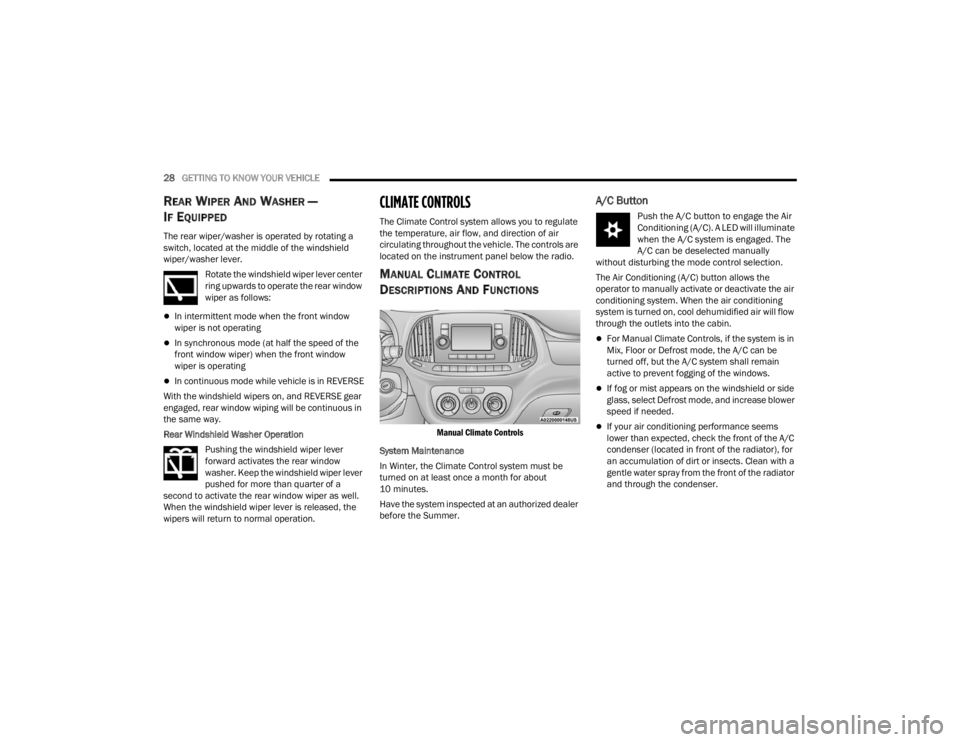
located on the instrument panel below the radio.
MANUAL CLIMATE CONTROL
D
ESCRIPTIONS AND FUNCTIONS
Manual Climate Controls
System Maintenance
In Winter, the Climate Control system must be
turned on at least once a month for about
10 minutes.
Have the system inspected at an authorized dealer
before the Summer.
A/C Button
Push the A/C button to engage the Air
Conditioning (A/C). A LED will illuminate
when the A/C system is engaged. The
A/C can be deselected manually
without disturbing the mode control selection.
The Air Conditioning (A/C) button allows the
operator to manually activate or deactivate the air
conditioning system. When the air conditioning
system is turned on, cool dehumidified air will flow
through the outlets into the cabin.
For Manual Climate Controls, if the system is in
Mix, Floor or Defrost mode, the A/C can be
turned off, but the A/C system shall remain
active to prevent fogging of the windows.
If fog or mist appears on the windshield or side
glass, select Defrost mode, and increase blower
speed if needed.
If your air conditioning performance seems
lower than expected, check the front of the A/C
condenser (located in front of the radiator), for
an accumulation of dirt or insects. Clean with a
gentle water spray from the front of the radiator
and through the condenser.
22_VM_OM_EN_USC_t.book Page 28
Page 31 of 260

GETTING TO KNOW YOUR VEHICLE29
(Continued)
Recirculation Button
Press and release this button to change
the system between recirculation mode
and outside air mode. The Recirculation
indicator and the A/C indicator
illuminate when the Recirculation button is
pressed. Recirculation can be used when outside
conditions such as smoke, odors, dust, or high
humidity are present. Recirculation can be used in
all modes. Recirculation may be unavailable
(button on the touchscreen greyed out) if
conditions exist that could create fogging on the
inside of the windshield. The A/C can be
deselected manually without disturbing the mode
control selection. Continuous use of the
Recirculation mode may make the inside air stuffy
and window fogging may occur. Extended use of
this mode is not recommended. Recirculation
mode may automatically adjust to optimize
customer experience for warming, cooling,
dehumidification, etc.
In cold weather, use of Recirculation mode may
lead to excessive window fogging. The
Recirculation feature may be unavailable if
conditions exist that could create fogging on the
inside of the windshield.
Front Defrost Setting
Use Defrost mode with maximum
temperature settings for best
windshield and side window defrosting
and defogging. Turn the knob to the
Front Defrost position. Air comes from the
windshield and side window demist outlets.
Rear Defrost Button — If Equipped
Push and release the Rear Defrost
Control button to turn on the rear
window defroster and the heated
outside mirrors (if equipped). An
indicator will illuminate when the rear window
defroster is on. The rear window defroster
automatically turns OFF after 20 minutes.Temperature Control
Temperature Control regulates the temperature of
the air forced through the climate system.
The temperature increases as you turn
the temperature control knob clockwise.
The temperature decreases as you turn
the temperature control knob
counterclockwise.
Blower Control
There are four blower speeds. Use this
control to regulate the amount of air
forced through the system in any mode
you select. The blower speed increases
as you move the control clockwise from the OFF
position.
CAUTION!
Failure to follow these cautions can cause
damage to the heating elements:
Use care when washing the inside of the rear
window. Do not use abrasive window cleaners
on the interior surface of the window. Use a
soft cloth and a mild washing solution, wiping
parallel to the heating elements. Labels can
be peeled off after soaking with warm water.
Do not use scrapers, sharp instruments, or
abrasive window cleaners on the interior
surface of the window.
Keep all objects a safe distance from the
window.
CAUTION!
2
22_VM_OM_EN_USC_t.book Page 29
Page 32 of 260

30GETTING TO KNOW YOUR VEHICLE
Mode Control
Rotate this control to change the airflow
distribution mode. The airflow
distribution mode can be adjusted so air
comes from the instrument panel
outlets, floor outlets, defrost outlets and demist
outlets. The Mode settings are as follows:
Panel Mode
Air comes from the outlets in the
instrument panel. Each of these outlets
can be individually adjusted to direct the
flow of air. The air vanes of the center
outlets and outboard outlets can be moved up and
down or side to side to regulate airflow direction.
There is a shut-off wheel located below the air
vanes to shut off or adjust the amount of airflow
from these outlets.
Bi-Level Mode
Air comes from the instrument panel
outlets and floor outlets. A slight amount
of air is directed through the defrost and
side window demister outlets.
NOTE:Bi-Level mode is designed under comfort condi -
tions to provide cooler air out of the panel outlets
and warmer air from the floor outlets.
Floor Mode
Air comes from the floor outlets. A slight
amount of air is directed through the
defrost and side window demister
outlets.
Mix Mode
Air is directed through the floor, defrost,
and side window demister outlets. This
setting works best in cold or snowy
conditions that require extra heat to the
windshield. This setting is good for maintaining
comfort while reducing moisture on the
windshield.
OPERATING TIPS
Refer to the chart at the end of this section for
suggested control settings for various weather
conditions.
Summer Operation
The engine cooling system must be protected with
a high-quality antifreeze coolant to provide proper
corrosion protection and to protect against engine
overheating. OAT coolant (conforming to
MS.90032) is recommended Ú page 240.
Winter Operation
To ensure the best possible heater and defroster
performance, make sure the engine cooling
system is functioning properly and the proper
amount, type, and concentration of coolant is used
Úpage 240. Use of the Air Recirculation mode
during Winter months is not recommended
because it may cause window fogging.
Vacation/Storage
For information on maintaining the Climate Control
system when the vehicle is being stored for an
extended period of time, see Ú page 233.
Window Fogging
Vehicle windows tend to fog on the inside of the
glass in mild, rainy and/or humid weather. To clear
the windows, select Defrost or Mix mode and
increase the front blower speed. Do not use the
Recirculation mode without A/C for long periods,
as fogging may occur.
Outside Air Intake
Make sure the air intake, located directly in front of
the windshield, is free of obstructions, such as
leaves. Leaves collected in the air intake may
reduce airflow, and if they enter the air distribution
box, they could plug the water drains. In Winter
months, make sure the air intake is clear of ice,
slush, and snow.
22_VM_OM_EN_USC_t.book Page 30
Page 56 of 260

54STARTING AND OPERATING
ENGINE BREAK-IN RECOMMENDATIONS
A long break-in period is not required for the engine
and drivetrain (transmission and axle) in your
vehicle.
Drive moderately during the first 300 miles
(500 km). After the initial 60 miles (100 km),
speeds up to 50 or 55 mph (80 or 90 km/h) are
desirable.
While cruising, brief full-throttle acceleration within
the limits of local traffic laws contributes to a good
break-in. Wide-open throttle acceleration in low
gear can be detrimental and should be avoided.
The engine oil installed in the engine at the factory
is a high-quality energy conserving type lubricant.
Oil changes should be consistent with anticipated
climate conditions under which vehicle operations
will occur. For the recommended viscosity and
quality grades Ú page 240.
NOTE:A new engine may consume some oil during its first
few thousand miles (kilometers) of operation. This
should be considered a normal part of the break-in
and not interpreted as a concern. Please check
your oil level with the engine oil indicator often
during the break-in period. Add oil as required.
PARKING BRAKE
Before leaving the vehicle, make sure that the
parking brake is fully applied. Also, be certain to
leave an automatic transmission in PARK.
The parking brake lever is located in the center
console. To apply the parking brake, pull the lever
up as firmly as possible. To release the parking
brake, pull the lever up slightly, push the center
button, then lower the lever completely.
Parking Brake
When the parking brake is applied with the ignition
switch in the ON position, the Brake Warning Light
in the instrument cluster display will illuminate.
NOTE:
When the parking brake is applied and the auto
-
matic transmission is placed in gear, the Brake
Warning Light will flash. If vehicle speed is
detected, a chime will sound to alert the driver.
Fully release the parking brake before
attempting to move the vehicle.
This light only shows that the parking brake is
applied. It does not show the degree of brake
application.
When parking on a hill, it is important to turn the
front wheels toward the curb on a downhill grade
and away from the curb on an uphill grade. For
vehicles equipped with an automatic transmission,
apply the parking brake before placing the gear
selector in PARK, otherwise the load on the
transmission locking mechanism may make it
difficult to move the gear selector out of PARK. The
parking brake should always be applied whenever
the driver is not in the vehicle.
CAUTION!
Never use Non-Detergent Oil or Straight Mineral
Oil in the engine or damage may result.
22_VM_OM_EN_USC_t.book Page 54
Page 58 of 260

56STARTING AND OPERATING
KEY IGNITION PARK INTERLOCK
This vehicle is equipped with a Key Ignition Park
Interlock which requires the transmission to be in
PARK before the ignition can be turned to the full
STOP (OFF/LOCK) (key removal) position. The key
can only be removed from the ignition when the
ignition is in the STOP (OFF/LOCK) position, and
once removed, the transmission is locked in PARK.
BRAKE/TRANSMISSION SHIFT
I
NTERLOCK (BTSI) SYSTEM
This vehicle is equipped with a BTSI that holds the
transmission gear selector in PARK unless the
brakes are applied. To shift the transmission out of
PARK, the ignition must be in the MAR (ON/RUN)
position (engine running or not) and the brake
pedal must be pressed. The brake pedal must also be pressed to shift from
NEUTRAL into DRIVE or REVERSE when the vehicle
is stopped or moving at low speeds.
9-SPEED AUTOMATIC TRANSMISSION
The transmission gear range (PRND) is displayed
both beside the gear selector and in the
instrument cluster display. To select a gear range,
push the lock button on the gear selector and
move the lever rearward or forward. You must also
press the brake pedal to shift the transmission out
of PARK (or NEUTRAL, when the vehicle is stopped
or moving at low speeds). Select the DRIVE range
for normal driving.
NOTE:In the event of a mismatch between the gear
selector position and the actual transmission gear
(for example, driver selects REVERSE while driving
forward), the position indicator will blink continu
-
ously until the selector is returned to the proper
position, or the requested shift can be completed.
The electronically controlled transmission adapts
its shift schedule based on driver inputs, along
with environmental and road conditions. The
transmission electronics are self-calibrating;
therefore, the first few shifts on a new vehicle may
be somewhat abrupt. This is a normal condition,
and precision shifts will develop within a few
hundred miles or kilometers. The 9-speed transmission has been developed to
meet the needs of current and future FWD/AWD
vehicles. Software and calibration is refined to
optimize the customer’s driving experience and
fuel economy. By design, some vehicle and
driveline combinations utilize NINTH gear only in
very specific driving situations and conditions.
Only shift from DRIVE to PARK or REVERSE when
the accelerator pedal is released and the vehicle is
stopped. Be sure to keep your foot on the brake
pedal when shifting between these gears.
The transmission gear selector provides PARK,
REVERSE, NEUTRAL, DRIVE, and Electronic Range
Select (ERS) shift positions. Manual downshifts can
be made using the ERS shift control. Moving the gear
selector into the ERS “-”/”+” position (beside the
DRIVE position) activates ERS mode, displays the
current gear in the instrument cluster, and prevents
automatic upshifts beyond this gear. In ERS mode,
toggling the gear selector forward “-” or rearward “+”
will change the highest available gear
Ú
page 59.
NOTE:If the gear selector cannot be moved to the PARK,
REVERSE, or NEUTRAL position (when pushed
forward) it is probably in the ERS “+”/”-” position
(beside the DRIVE position). In ERS mode, the
transmission gear limit (1, 2, 3, etc.) is displayed in
the instrument cluster. Move the gear selector to
the right (into the DRIVE [D] position) for access to
PARK, REVERSE, and NEUTRAL.
CAUTION!
Shift into or out of PARK or REVERSE only after
the vehicle has come to a complete stop.
Do not shift between PARK, REVERSE,
NEUTRAL, or DRIVE when the engine is above
idle speed.
Before shifting into any gear, make sure your
foot is firmly pressing the brake pedal.
22_VM_OM_EN_USC_t.book Page 56