2022 RAM PROMASTER CITY steering wheel
[x] Cancel search: steering wheelPage 4 of 260
2
INTRODUCTION
SYMBOLS KEY ...........................................................7
VAN CONVERSIONS/CAMPERS ..............................7
VEHICLE MODIFICATIONS/ALTERATIONS .............7
SYMBOL GLOSSARY.................................................8
GETTING TO KNOW YOUR VEHICLE
KEYS ....................................................................... 10 Key Fob .............................................................10
SENTRY KEY ........................................................... 12
IGNITION SWITCH .................................................. 12
DOORS ................................................................... 13
Power Door Locks ............................................13
Auto Unlock Doors ............................................13
Sliding Side Door ..............................................13
Double Rear Swing Doors ................................15
Child-Protection Door Lock System.................15
STEERING WHEEL.................................................. 16
Tilt/Telescoping Steering Column ...................16
SEATS ...................................................................... 16
Manual Adjustment (Front Seats) ...................16
Folding Rear Seat — If Equipped .....................17
Heated Seats — If Equipped ............................18
Head Restraints ...............................................19 UCONNECT VOICE RECOGNITION ........................21
Introducing Voice Recognition.........................21
Basic Voice Commands ...................................21
Get Started .......................................................21
Additional Information .....................................21
MIRRORS ...............................................................22
Inside Rearview Mirror .....................................22
Vanity Mirror .....................................................22
Outside Mirrors ................................................22
EXTERIOR LIGHTS ..................................................24
Multifunction Lever ..........................................24
Headlights ........................................................24
Daytime Running Lights (DRLs) —
If Equipped .......................................................24
High/Low Beam Switch....................................24
Flash-To-Pass ..................................................24
Parking Lights ..................................................24
Follow Me Home/Headlight Delay ..................24
Fog Lights — If Equipped .................................25
Turn Signals ......................................................25
Lane Change Assist..........................................25
INTERIOR LIGHTS ..................................................25
Courtesy/Interior Lights ...................................25
WIPERS AND WASHERS ......................................26
Front Wiper Operation......................................27
Rear Wiper And Washer —If Equipped ............28 CLIMATE CONTROLS ............................................ 28
Manual Climate Control Descriptions And
Functions .......................................................... 28
Operating Tips .................................................. 30
INTERIOR STORAGE AND EQUIPMENT ............... 31
Storage ............................................................. 31
USB Control — If Equipped .............................. 32
Power Outlets .................................................. 32
WINDOWS ............................................................. 34
Power Window Controls —If Equipped ........... 34
Window Bar Grates — If Equipped .................. 35
Wind Buffeting .................................................35
HOOD....................................................................... 36
Opening............................................................. 36
Closing ..............................................................36
CARGO AREA FEATURES ...................................... 37
Rear Cargo Tie-Downs ..................................... 37
ROOF RACK — IF EQUIPPED................................. 37
GETTING TO KNOW YOUR
INSTRUMENT PANEL
INSTRUMENT CLUSTER......................................... 39
Instrument Cluster Descriptions ..................... 40
INSTRUMENT CLUSTER DISPLAY ....................... 40
Location And Controls...................................... 40
Change Engine Oil — If Equipped ................... 41
Instrument Cluster Display Menu Items ......... 42
22_VM_OM_EN_USC_t.book Page 2
Page 6 of 260

4
MULTIMEDIA
UCONNECT SYSTEMS ........................................... 78
CYBERSECURITY ................................................... 78
UCONNECT SETTINGS .......................................... 79 Uconnect 3/3 NAV Settings .............................79
UCONNECT INTRODUCTION.................................. 88
Identifying Your Radio ......................................88
Safety And General Information ......................90
UCONNECT MODES ............................................... 91
Radio Mode ......................................................91
Media Mode......................................................98
Phone Mode ................................................. 100
NAVIGATION MODE — IF EQUIPPED ..................110
Operating Navigation Mode —If Equipped ... 110
STEERING WHEEL AUDIO CONTROLS —
IF EQUIPPED ........................................................ 128
Radio Operation ............................................ 128
Media Mode................................................... 129
RAM TELEMATICS - IF EQUIPPED ...................... 129
Ram Telematics General Information .......... 129
RADIO OPERATION AND MOBILE PHONES ..... 130
Regulatory And Safety Information .............. 130
SAFETY
SAFETY FEATURES .............................................. 131Four-Wheel Anti-Lock Brake System (ABS).. 131
Electronic Brake Control (EBC) System ...... 132
AUXILIARY DRIVING SYSTEMS.......................... 135
Tire Pressure Monitoring System (TPMS) .... 135
OCCUPANT RESTRAINT SYSTEMS ................... 137
Occupant Restraint Systems ........................ 137
Important Safety Precautions ...................... 137Seat Belt Systems ........................................ 138Supplemental Restraint Systems (SRS) ...... 144Child Restraints ............................................. 152
SAFETY TIPS ....................................................... 168
Transporting Passengers .............................. 168Transporting Pets ......................................... 168
Safety Checks You Should Make Inside
The Vehicle ................................................... 168
Periodic Safety Checks You Should Make
Outside The Vehicle ...................................... 169
Exhaust Gas................................................... 170
Carbon Monoxide Warnings ........................ 170
IN CASE OF EMERGENCY
HAZARD WARNING FLASHERS......................... 171
JACKING AND TIRE CHANGING ......................... 171
Preparations For Jacking ............................. 171
Jack Location — If Equipped ......................... 172
Removing The Spare Tire —If Equipped....... 172 Jacking Instructions ...................................... 174
Vehicles With Alloy Wheels ........................... 177
Vehicles Equipped With Wheel Covers ........ 178
TIRE SERVICE KIT — IF EQUIPPED .................... 179
Tire Service Kit Storage ................................ 179Tire Service Kit Usage ................................... 179
JUMP STARTING .................................................. 181
Preparations For Jump Starting ................... 181Jump Starting Procedure .............................. 182
IF YOUR ENGINE OVERHEATS ........................... 183
IGNITION KEY REMOVAL OVERRIDE ................. 184
GEAR SELECTOR OVERRIDE .............................. 184
FREEING A STUCK VEHICLE .............................. 185
TOWING A DISABLED VEHICLE .......................... 187
ENHANCED ACCIDENT RESPONSE SYSTEM
(EARS) .................................................................. 188
EVENT DATA RECORDER (EDR) ......................... 188
SERVICING AND MAINTENANCE
SCHEDULED SERVICING .................................... 189
Maintenance Plan ......................................... 190
ENGINE COMPARTMENT .................................... 193
Engine Compartment — 2.4L ....................... 193
Checking Oil Level ........................................ 194
Adding Washer Fluid .................................... 194
Maintenance-Free Battery ........................... 194
Pressure Washing ......................................... 195
22_VM_OM_EN_USC_t.book Page 4
Page 18 of 260
16GETTING TO KNOW YOUR VEHICLE
NOTE:For emergency exit from the rear seats when the
Child-Protection Door Lock system is engaged,
manually raise the door lock knob to the unlocked
position, roll down the window, and open the door
using the outside door handle.
STEERING WHEEL
TILT/TELESCOPING STEERING COLUMN
This feature allows you to tilt the steering column
upward or downward. It also allows you to lengthen
or shorten the steering column. The steering
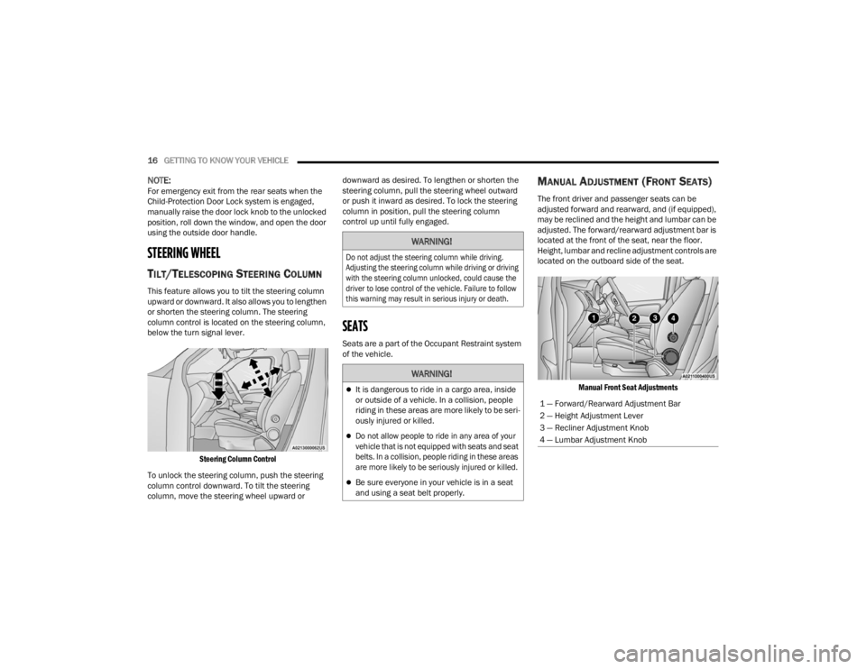
column control is located on the steering column,
below the turn signal lever.
Steering Column Control
To unlock the steering column, push the steering
column control downward. To tilt the steering
column, move the steering wheel upward or downward as desired. To lengthen or shorten the
steering column, pull the steering wheel outward
or push it inward as desired. To lock the steering
column in position, pull the steering column
control up until fully engaged.
SEATS
Seats are a part of the Occupant Restraint system
of the vehicle.
MANUAL ADJUSTMENT (FRONT SEATS)
The front driver and passenger seats can be
adjusted forward and rearward, and (if equipped),
may be reclined and the height and lumbar can be
adjusted. The forward/rearward adjustment bar is
located at the front of the seat, near the floor.
Height, lumbar and recline adjustment controls are
located on the outboard side of the seat.
Manual Front Seat Adjustments
WARNING!
Do not adjust the steering column while driving.
Adjusting the steering column while driving or driving
with the steering column unlocked, could cause the
driver to lose control of the vehicle. Failure to follow
this warning may result in serious injury or death.
WARNING!
It is dangerous to ride in a cargo area, inside
or outside of a vehicle. In a collision, people
riding in these areas are more likely to be seri -
ously injured or killed.
Do not allow people to ride in any area of your
vehicle that is not equipped with seats and seat
belts. In a collision, people riding in these areas
are more likely to be seriously injured or killed.
Be sure everyone in your vehicle is in a seat
and using a seat belt properly.
1 — Forward/Rearward Adjustment Bar
2 — Height Adjustment Lever
3 — Recliner Adjustment Knob
4 — Lumbar Adjustment Knob
22_VM_OM_EN_USC_t.book Page 16
Page 26 of 260
24GETTING TO KNOW YOUR VEHICLE
EXTERIOR LIGHTS
MULTIFUNCTION LEVER
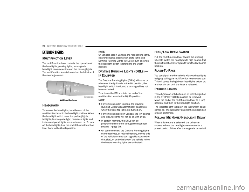
The multifunction lever controls the operation of
the headlights, parking lights, turn signals,
headlight beam selection and the passing lights.
The multifunction lever is located on the left side of
the steering column.
Multifunction Lever
HEADLIGHTS
To turn on the headlights, turn the end of the
multifunction lever to the headlight position. When
the headlight switch is on, the parking lights,
taillights, license plate light, clearance lights and
instrument panel lights are also turned on. To turn
off the headlights, turn the end of the multifunction
lever back to the O (off) position.
NOTE:On vehicles sold in Canada, the rear parking lights,
clearance lights, sidemarker, plate lights and
Daytime Running Lights (DRLs) will turn on when
the headlight switch is rotated to the O (off)
position.
DAYTIME RUNNING LIGHTS (DRLS) —
I
F EQUIPPED
The Daytime Running Lights (DRLs) will come on
whenever the ignition is in the ON position, the
headlight switch is off, and a turn signal has not
been activated.
To activate the DRLs, rotate the end of the
multifunction lever to the O (off) position.
NOTE:
For vehicles sold in Canada, the Daytime
Running Lights will automatically deactivate
when the front fog lights are turned on.
For vehicles not sold in Canada, the low beams
and side/taillights will not be on with DRLs.
In certain markets, the DRLs can be
programmed on or off through the Uconnect
system Ú page 79.
On some vehicles, the Daytime Running Lights
may deactivate, or reduce intensity, on one side
of the vehicle (when a turn signal is activated on
that side), or on both sides of the vehicle (when
the hazard warning lights are activated).
HIGH/LOW BEAM SWITCH
Pull the multifunction lever toward the steering
wheel to switch the headlights to high beams. Pull
the multifunction lever again to turn the low beams
back on.
FLASH-TO-PASS
You can signal another vehicle with your headlights
by lightly pulling the multifunction lever toward you.
This will cause the high beam headlights to turn on,
and remain on, until the lever is released.
PARKING LIGHTS
These lights can only be turned on with the ignition
in the STOP (OFF/LOCK) position or removed.
Move the end of the multifunction lever to O (off)
position, and then to the headlight position.
The indicator light telltale in the instrument panel
comes on. The lights stay on until the next ignition
cycle is performed.
FOLLOW ME HOME/HEADLIGHT DELAY
When this feature is selected, the driver can
choose to have the headlights remain on for a
preset period of time after the engine is turned off.
22_VM_OM_EN_USC_t.book Page 24
Page 27 of 260
GETTING TO KNOW YOUR VEHICLE25
Activation
Remove the key or turn the ignition to the STOP
(OFF/LOCK) position, and pull the multifunction
lever toward the steering wheel within two
minutes. Each time the lever is pulled, the
activation of the lights will be extended by 30
seconds. The activation of the lights can be
extended to a maximum of 210 seconds.
Deactivation
Pull the multifunction lever toward the steering
wheel and hold it for more than two seconds.
FOG LIGHTS — IF EQUIPPED
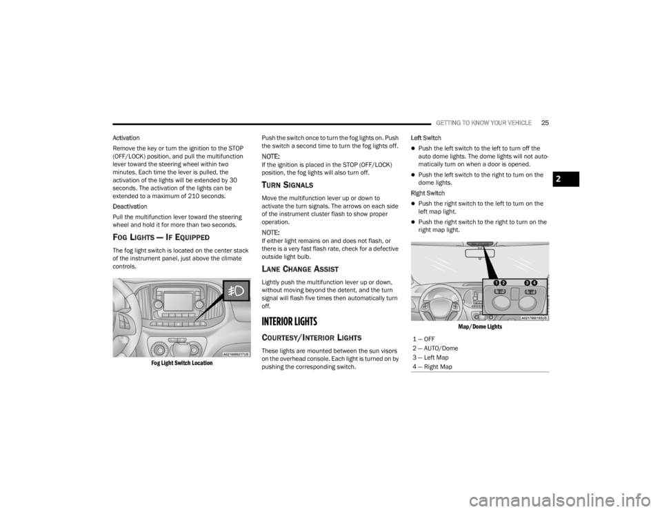
The fog light switch is located on the center stack
of the instrument panel, just above the climate
controls.
Fog Light Switch Location
Push the switch once to turn the fog lights on. Push
the switch a second time to turn the fog lights off.
NOTE:If the ignition is placed in the STOP (OFF/LOCK)
position, the fog lights will also turn off.
TURN SIGNALS
Move the multifunction lever up or down to
activate the turn signals. The arrows on each side
of the instrument cluster flash to show proper
operation.
NOTE:If either light remains on and does not flash, or
there is a very fast flash rate, check for a defective
outside light bulb.
LANE CHANGE ASSIST
Lightly push the multifunction lever up or down,
without moving beyond the detent, and the turn
signal will flash five times then automatically turn
off.
INTERIOR LIGHTS
COURTESY/INTERIOR LIGHTS
These lights are mounted between the sun visors
on the overhead console. Each light is turned on by
pushing the corresponding switch. Left Switch
Push the left switch to the left to turn off the
auto dome lights. The dome lights will not auto -
matically turn on when a door is opened.
Push the left switch to the right to turn on the
dome lights.
Right Switch
Push the right switch to the left to turn on the
left map light.
Push the right switch to the right to turn on the
right map light.
Map/Dome Lights
1 — OFF
2 — AUTO/Dome
3 — Left Map
4 — Right Map
2
22_VM_OM_EN_USC_t.book Page 25
Page 42 of 260
40GETTING TO KNOW YOUR INSTRUMENT PANEL
INSTRUMENT CLUSTER DESCRIPTIONS
1. Speedometer
Indicates vehicle speed.
2. Fuel Gauge
The pointer shows the level of fuel in the
fuel tank when the ignition switch is in the
ON/RUN position.
The fuel pump arrow symbol
points to the side of the vehicle
where the fuel door is located.
3.Temperature Gauge
The temperature gauge shows engine
coolant temperature. Any reading within the
normal range indicates that the engine
cooling system is operating satisfactorily.
The pointer will likely indicate a higher
temperature when driving in hot weather or
up mountain grades. It should not be
allowed to exceed the upper limits of the
normal operating range. 4. Tachometer
Indicates the engine speed in revolutions
per minute (RPM x 1000).
5. Instrument Cluster Display
When the appropriate conditions exist, this
display shows the instrument cluster
display messages Ú page 40.
INSTRUMENT CLUSTER DISPLAY
Your vehicle will be equipped with an instrument
cluster display, which offers useful information to
the driver. With the ignition in the OFF mode,
opening/closing of a door will activate the display
for viewing, and display the total miles, or
kilometers, in the odometer. The steering wheel
mounted controls allow you to scroll through the
main menus and submenus. You can access the
specific information you want and make selections
and adjustments.
LOCATION AND CONTROLS
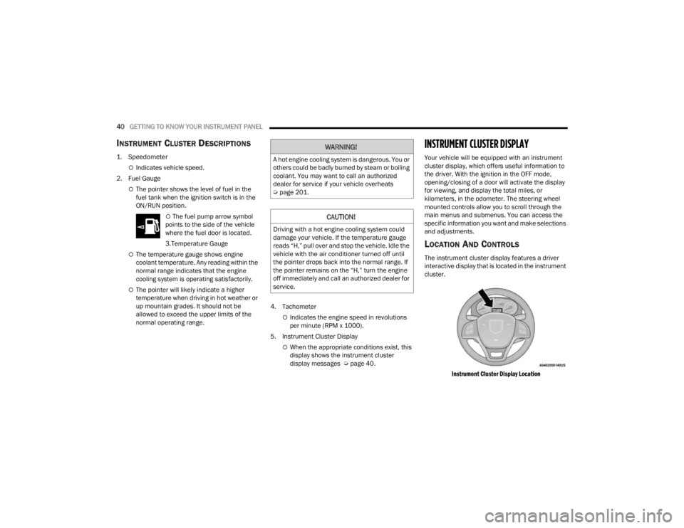
The instrument cluster display features a driver
interactive display that is located in the instrument
cluster.
Instrument Cluster Display Location
WARNING!
A hot engine cooling system is dangerous. You or
others could be badly burned by steam or boiling
coolant. You may want to call an authorized
dealer for service if your vehicle overheats
Úpage 201.
CAUTION!
Driving with a hot engine cooling system could
damage your vehicle. If the temperature gauge
reads “H,” pull over and stop the vehicle. Idle the
vehicle with the air conditioner turned off until
the pointer drops back into the normal range. If
the pointer remains on the “H,” turn the engine
off immediately and call an authorized dealer for
service.
22_VM_OM_EN_USC_t.book Page 40
Page 43 of 260
GETTING TO KNOW YOUR INSTRUMENT PANEL41
The menu items described below are an example
of what can be found in the vehicle's menu:
Dimmer
Speed Beep
Trip A / B (options are selectable through the
steering wheel stalk)
Buzzer Volume
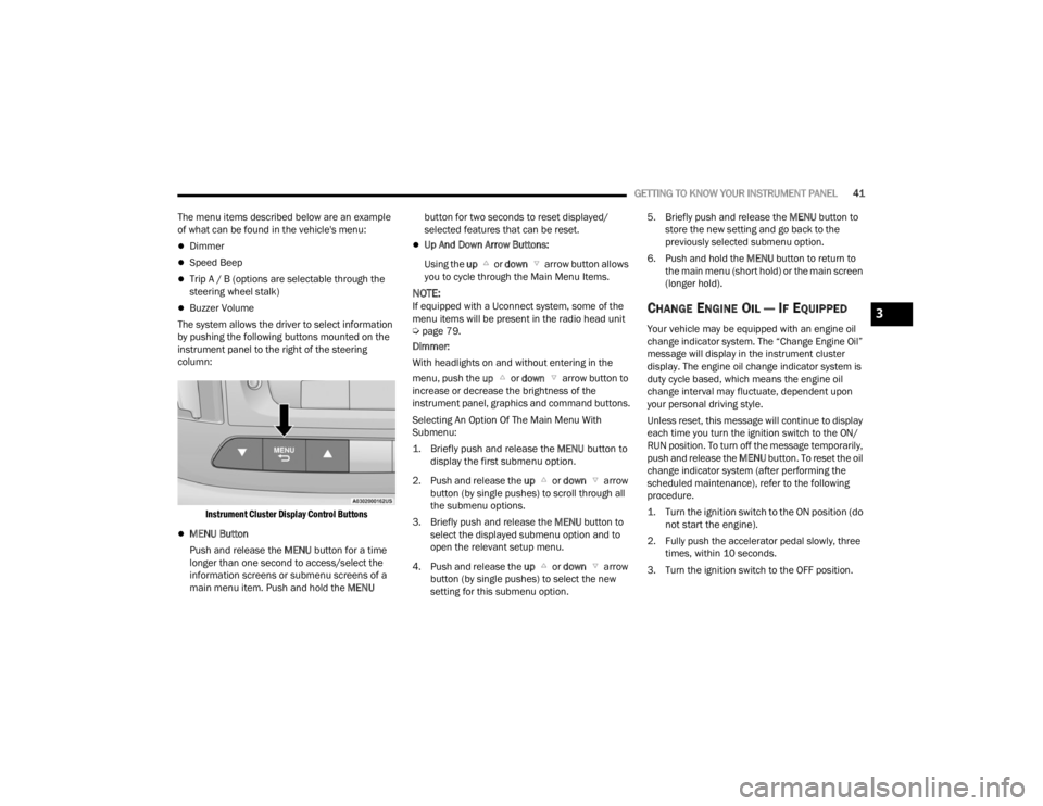
The system allows the driver to select information
by pushing the following buttons mounted on the
instrument panel to the right of the steering
column:
Instrument Cluster Display Control Buttons
MENU Button
Push and release the MENU button for a time
longer than one second to access/select the
information screens or submenu screens of a
main menu item. Push and hold the MENU button for two seconds to reset displayed/
selected features that can be reset.
Up And Down Arrow Buttons:
Using the up or down arrow button allows
you to cycle through the Main Menu Items.
NOTE:If equipped with a Uconnect system, some of the
menu items will be present in the radio head unit
Ú page 79.
Dimmer:
With headlights on and without entering in the
menu, push the up or down arrow button to
increase or decrease the brightness of the
instrument panel, graphics and command buttons.
Selecting An Option Of The Main Menu With
Submenu:
1. Briefly push and release the
MENU
button to
display the first submenu option.
2. Push and release the up or down arrow
button (by single pushes) to scroll through all
the submenu options.
3. Briefly push and release the MENU button to
select the displayed submenu option and to
open the relevant setup menu.
4. Push and release the up or down arrow
button (by single pushes) to select the new
setting for this submenu option. 5. Briefly push and release the MENU
button to
store the new setting and go back to the
previously selected submenu option.
6. Push and hold the MENU button to return to
the main menu (short hold) or the main screen
(longer hold).CHANGE ENGINE OIL — IF EQUIPPED
Your vehicle may be equipped with an engine oil
change indicator system. The “Change Engine Oil”
message will display in the instrument cluster
display. The engine oil change indicator system is
duty cycle based, which means the engine oil
change interval may fluctuate, dependent upon
your personal driving style.
Unless reset, this message will continue to display
each time you turn the ignition switch to the ON/
RUN position. To turn off the message temporarily,
push and release the MENU button. To reset the oil
change indicator system (after performing the
scheduled maintenance), refer to the following
procedure.
1. Turn the ignition switch to the ON position (do not start the engine).
2. Fully push the accelerator pedal slowly, three times, within 10 seconds.
3. Turn the ignition switch to the OFF position.
3
22_VM_OM_EN_USC_t.book Page 41
Page 62 of 260
60STARTING AND OPERATING
NOTE:To select the proper gear position for maximum
deceleration (engine braking), move the gear
selector into the ERS position, then simply press
and hold it forward “-”. The transmission will shift
to the range from which the vehicle can best be
slowed down.
POWER STEERING
The standard power steering system provides
increased vehicle response and ease of
maneuverability. The system will provide
mechanical steering capability if power assist is
lost.
If for some reason the power assist is interrupted,
it will still be possible to steer your vehicle. Under
these conditions, you will observe a substantial
increase in steering effort, especially at very low
vehicle speeds and during parking maneuvers.
NOTE:
Increased noise levels at the end of the steering
wheel travel are considered normal and do not
indicate that there is a problem with the power
steering system.
Upon initial start-up in cold weather, the power
steering pump may make noise for a short
amount of time. This is due to the cold, thick
fluid in the steering system. This noise should
be considered normal, and it does not in any
way damage the steering system.
POWER STEERING FLUID CHECK
Checking the power steering fluid level at a defined
service interval is not required. The fluid should
only be checked if a leak is suspected, abnormal
noises are apparent, and/or the system is not
functioning as anticipated. Coordinate inspection
efforts through an authorized dealer. If necessary, add fluid to restore to the proper
indicated level. With a clean cloth, wipe any spilled
fluid from all surfaces Ú
page 241.CRUISE CONTROL — IF EQUIPPED
When engaged, the Cruise Control takes over
accelerator operations at speeds greater than
25 mph (40 km/h).
The Cruise Control buttons are located on the right
side of the steering wheel.
WARNING!
Do not downshift for additional engine braking
on a slippery surface. The drive wheels could
lose their grip and the vehicle could skid,
causing a collision or personal injury.
CAUTION!
Prolonged operation of the steering system at
the end of the steering wheel travel will increase
the steering fluid temperature and it should be
avoided when possible. Damage to the power
steering pump may occur.
WARNING!
Fluid level should be checked on a level surface
and with the engine off to prevent injury from
moving parts and to ensure accurate fluid level
reading. Do not overfill. Use only the
manufacturer recommended power steering
fluid.
CAUTION!
Do not use chemical flushes in your power
steering system as the chemicals can damage
your power steering components. Such damage
is not covered by the New Vehicle Limited
Warranty.
22_VM_OM_EN_USC_t.book Page 60