Page 129 of 260

MULTIMEDIA127
Adding A Location Using Search
1. In the Main Menu, press “Search”.
2. Enter the name or address of a location using the touchscreen keyboard.
3. Select the desired location, and then press “Show In Map”.
4. The Map View will show the location. Press the pop-up menu button.
5. Press “Add to My Places”.
6. The name of the location will appear in the edit screen. You can edit the name of the location
for easy recognition.
7. Press “Done” to save your location in the My Places list.
Setting Your Home Location
1. In the Main Menu, press “My Places”.
2. Press “Home” .
3. To select a location for home, do one of the following:
Zoom in on the map at the location you want
to select. Press and hold to select the loca -
tion, then press the home icon next to the
name of the location.
You can also search for a location using the
search function. Select “Set Home Loca -
tion.”
DELETING A LOCATION FROM MY PLACES
Deleting A Recent Destination From My Places
1. In the main menu, select “My Places”.
2. Press “Recent Destinations”.
3. Press “Edit List”.
4. Select the destination(s) you want to delete.
5. Press the Delete button.
Deleting A Location From My Places
1. In the main menu, select “My Places”.
2. Press “Edit List”.
3. Select the destination(s) you want to delete.
4. Press the Delete button.
Getting Help
Press the Help button in the Main menu or from
the Settings menu to see the following information:
About : Press this button to view information about
your Uconnect system. This information includes:
Serial number
Application version
Installed maps
Legal information, such as Copyright and
Licenses for EULA and Open Source
Important Safety Notices And Warnings
GLOBAL POSITIONING SYSTEM
The Global Positioning System (GPS) is a
satellite-based system that provides location and
timing information around the globe. GPS is
operated and controlled under the sole
responsibility of the Government of the United
States of America, which is responsible for its
availability and accuracy. Any changes in GPS
availability and accuracy, or in environmental
conditions, may impact the operation of this
Navigation system. TomTom® does not accept any
liability for the availability and accuracy of GPS.
USE WITH CARE
Use of TomTom® navigation while driving still
means that you need to drive with due care and
attention.
SAFETY SETTINGS
We recommend using the safety settings to make
your driving as safe as possible. These are some of
the options included in the safety settings:
Show safety reminders
Warn when driving faster than allowed
You can also drive more safely by using voice
commands to control navigation Ú page 123.
5
22_VM_OM_EN_USC_t.book Page 127
Page 130 of 260

128MULTIMEDIA
Copyright Notices
© 2021 TomTom®. All rights reserved. TomTom®
and the "two hands" logo are registered
trademarks of TomTom® N.V. or one of its
subsidiaries. Please see
www.tomtom.com/
en_us/legal/ for warranties and end user license
agreements applying to this product.
© 2021 TomTom®. All rights reserved. This
material is proprietary and the subject of copyright
protection and/or database rights protection and/
or other intellectual property rights owned by
TomTom® or its suppliers. The use of this material
is subject to the terms of a license agreement. Any
unauthorized copying or disclosure of this material
will lead to criminal and civil liabilities.
Data Source © 2021 TomTom® All rights reserved.
The software included in this product contains
copyrighted software that is licensed under the
GPL. A copy of that license can be viewed in the
License section. You can obtain the complete
corresponding source code from us for a period of
three years after our last shipment of this product.
For more information, visit
https://
www.tomtom.com/en_gb/opensource or
contact your local TomTom® customer support
team via
us.support.tomtom.com/app/
answers/list. Upon request, we will send you a CD
with the corresponding source code. Linotype, Frutiger and Univers are trademarks of
Linotype GmbH registered in the US Patent and
Trademark Office and may be registered in certain
other jurisdictions. MHei is a trademark of The
Monotype Corporation and may be registered in
certain jurisdictions.
STEERING WHEEL AUDIO CONTROLS —
IF EQUIPPED
The remote sound system controls are located on
the back surface of the steering wheel. Reach
behind the wheel to access the switches.
Remote Sound System Controls
The right-hand control is a rocker type switch with
a push button in the center. Pushing the top of the
switch will increase the volume, and pushing the
bottom of the switch will decrease the volume.
The push button located in the center of the
right-hand control to select the source (AM, FM,
SiriusXM®, or USB)
The left-hand control is a rocker type switch with a
push button in the center. The function of the left
hand control is different depending on which mode
you are in.
The following describes the left-hand control
operation in each mode.
RADIO OPERATION
Pushing the top of the switch will seek up for the
next available station and pushing the bottom of
the switch will seek down for the next available
station.
The button located in the center of the left-hand
control will tune to the next preset station that you
have programmed in the radio preset button.
22_VM_OM_EN_USC_t.book Page 128
Page 131 of 260
.
Pushing the bottom of the switch once goes to the
beginning of the curre")
MULTIMEDIA129
MEDIA MODE
Pushing the top of the switch once goes to the next
track on the selected media (USB/Bluetooth®).
Pushing the bottom of the switch once goes to the
beginning of the current track, or to the beginning
of the previous track if it is within eight seconds
after the current track begins to play.
RAM TELEMATICS - IF EQUIPPED
Ram Telematics is designed to help improve
safety, efficiency, and productivity. It gives you
complete visibility of your fleet options, whether
from behind a desk or on a mobile device while you
are on the go. You can log-in to view near real-time
and historical activity, including location, vehicle
health, and driver performance. Activating Ram Telematics In Your Vehicles
Before you get started you will need:
The Vehicle Identification Number (VIN) of each
vehicle you want to activate.
Your main user’s username and password; new
customers will be asked to register.
If you are a new customer, you will need
company credit card information or invoice
number as further proof of customer identifica
-
tion. Don’t worry, you will not be charged.
Go to activate.verizonconnect.com/ram/
#login. If you are an existing Verizon Connect
customer, enter your company’s log in creden -
tials. New customers will need to register to
create a new account.
Manually enter the VIN or upload a CSV file with
your VIN. A vehicle name is optional and can be
added later. Follow online instructions to
complete your vehicle entry.
Create a password and enter billing information.
An email will be sent to you to complete the final
step. After that, you will be ready to log-in and
access Verizon Connect Fleet!
You are good to go! You will receive an email
confirming your vehicles are now online.
For more information, or to learn more, visit
www.verizonconnect.com/ram/.
RAM TELEMATICS GENERAL
I
NFORMATION
Modification Statement
Marelli has not approved any changes or
modifications to this device by the user. Any
changes or modifications could void the user’s
authority to operate the equipment.
Marelli n'approuve aucune modification apportée
à l'appareil par l'utilisateur, quelle qu'en soit la
nature. Tout changement ou modification peuvent
annuler le droit d'utilisation de l'appareil par
l'utilisateur.5
22_VM_OM_EN_USC_t.book Page 129
Page 132 of 260
. Operation is subject to the
following two co")
130MULTIMEDIA
Interference Statement
This device complies with Part 15, 22, 24, and 27
of the FCC and Industry Canada licence-exempt
RSS standard(s). Operation is subject to the
following two conditions:(1) This device may not
cause interference, and(2) This device must
accept any interference, including interference
that may cause undesired operation of the device.
Le présent appareil est conforme aux CNR
d'Industrie Canada applicables aux appareils radio
exempts de licence. L'exploitation est autorisée
aux deux conditions suivantes:(1) l'appareil ne doit
pas produire de brouillage, et(2) l'utilisateur de
l'appareil doit accepter tout brouillage
radioélectrique subi, même si le broulliage est
susceptible d'en compromettre le fonctionnement.
RF Exposure
This equipment complies with FCC and IC radiation
exposure limits set forth for an uncontrolled
environment. The antenna should be installed and
operated with minimum distance of 8 in (20) cm
between the radiator and your body.
Cet appareil est conforme aux limites d'exposition
aux rayonnements de la IC pour environnement
non contrôlé. L'antenne doit être installé de façon
à garder une distance minmale de 20 centimètres
entre la source de rayonnements et votre corps.
RADIO OPERATION AND MOBILE PHONES
Under certain conditions, the mobile phone being
on in your vehicle can cause erratic or noisy
performance from your radio. This condition may
be lessened or eliminated by repositioning the
mobile phone within the vehicle. This condition is
not harmful to the radio. If your radio performance
does not satisfactorily improve from repositioning
the mobile phone, it is recommended that the
volume be turned down or off during mobile phone
operation when not using the Uconnect system.
REGULATORY AND SAFETY
I
NFORMATION
US/CANADA
Exposure to Radio Frequency Radiation
The radiated output power of the internal wireless
radio is far below the FCC and IC radio frequency
exposure limits. Nevertheless, the wireless radio
will be used in such a manner that the radio is 8 in
(20 cm) or further from the human body. The internal wireless radio operates within
guidelines found in radio frequency safety
standards and recommendations, which reflect
the consensus of the scientific community.
The radio manufacturer believes the internal
wireless radio is safe for use by consumers. The
level of energy emitted is far less than the
electromagnetic energy emitted by wireless
devices such as mobile phones. However, the use
of wireless radios may be restricted in some
situations or environments, such as aboard
airplanes. If you are unsure of restrictions, you are
encouraged to ask for authorization before turning
on the wireless radio Ú
page 245.
22_VM_OM_EN_USC_t.book Page 130
Page 133 of 260

SAFETY
SAFETY FEATURES
FOUR-WHEEL ANTI-LOCK BRAKE
S
YSTEM (ABS)
The ABS is designed to aid the driver in
maintaining vehicle control under adverse braking
conditions. The system")
131
(Continued)
SAFETY
SAFETY FEATURES
FOUR-WHEEL ANTI-LOCK BRAKE
S
YSTEM (ABS)
The ABS is designed to aid the driver in
maintaining vehicle control under adverse braking
conditions. The system operates with a separate
computer to modulate hydraulic pressure, to
prevent wheel lock-up and to help avoid skidding
on slippery surfaces.
The system's pump motor runs during an ABS stop
to provide regulated hydraulic pressure. The pump
motor makes a low humming noise during
operation, which is normal.
The ABS includes an amber ABS Warning Light.
When the light is illuminated, the ABS is not
functioning. The system reverts to standard
non-Anti-Lock Brakes. Turning the ignition OFF and
ON again may reset the ABS if the fault detected
was only momentary. When you are in a severe braking condition
involving the use of the ABS, you will experience
some pedal drop as the vehicle comes to a stop.
This is the result of the system reverting to the
base brake system.
Engagement of the ABS may be accompanied by a
pulsing sensation. You may also hear a clicking
noise. These occurrences are normal and indicate
that the system is functioning properly.
WARNING!
The ABS contains sophisticated electronic
equipment that may be susceptible to interfer
-
ence caused by improperly installed or high
output radio transmitting equipment. This
interference can cause possible loss of
anti-lock braking capability. Installation of
such equipment should be performed by qual -
ified professionals.
Pumping of the Anti-Lock Brakes will diminish
their effectiveness and may lead to a collision.
Pumping makes the stopping distance longer.
Just press firmly on your brake pedal when you
need to slow down or stop.
The ABS cannot prevent the natural laws of
physics from acting on the vehicle, nor can it
increase braking or steering efficiency beyond
that afforded by the condition of the vehicle
brakes and tires or the traction afforded.
The ABS cannot prevent collisions, including
those resulting from excessive speed in turns,
following another vehicle too closely, or hydro -
planing.
The capabilities of an ABS equipped vehicle
must never be exploited in a reckless or
dangerous manner that could jeopardize the
user’s safety or the safety of others.
WARNING!
6
22_VM_OM_EN_USC_t.book Page 131
Page 134 of 260

ELECTRONIC BRAKE CONTROL (EBC)
S
YSTEM
Your vehicle is equipped with an advanced
Electronic Brake Control (EBC) system that
includes the Brake Assist System (BAS), Tractio")
132SAFETY
(Continued)
ELECTRONIC BRAKE CONTROL (EBC)
S
YSTEM
Your vehicle is equipped with an advanced
Electronic Brake Control (EBC) system that
includes the Brake Assist System (BAS), Traction
Control System (TCS), Hill Start Assist (HSA),
Electronic Stability Control (ESC), Electronic Roll
Mitigation (ERM) and Trailer Sway Control (TSC). All
systems work together to enhance vehicle stability
and control in various driving conditions and are
commonly referred to as ESC.
Brake Assist System (BAS)
BAS is designed to optimize the vehicle’s braking
capability during emergency braking maneuvers.
The system detects an emergency braking
situation by sensing the rate and amount of brake
application and then applies optimum pressure to
the brakes. This can help reduce braking
distances. The BAS complements the Anti-Lock
Brake System (ABS). Applying the brakes very
quickly results in the best BAS assistance. To
receive the benefit of the system, you must apply
continuous braking pressure during the stopping
sequence (do not “pump” the brakes). Do not
reduce brake pedal pressure unless braking is no
longer desired. Once the brake pedal is released,
the BAS is deactivated.Electronic Stability Control (ESC)
ESC enhances directional control and stability of
the vehicle under various driving conditions. ESC
corrects for over/under steering of the vehicle by
applying the brake of the appropriate wheel to
counteract the above conditions. Engine power
may also be reduced to help the vehicle maintain
the desired path.
Oversteer — when the vehicle is turning more
than appropriate for the steering wheel position.
Understeer — when the vehicle is turning less
than appropriate for the steering wheel position. ESC uses sensors in the vehicle to determine the
vehicle path intended by the driver and compares
it to the actual path of the vehicle. When the actual
path does not match the intended path, ESC
applies the brake of the appropriate wheel to
assist in counteracting the oversteer or understeer
condition.
WARNING!
The Brake Assist System (BAS) cannot prevent
the natural laws of physics from acting on the
vehicle, nor can it increase the traction afforded
by prevailing road conditions. BAS cannot
prevent collisions, including those resulting from
excessive speed in turns, driving on very slippery
surfaces, or hydroplaning. The capabilities of a
BAS-equipped vehicle must never be exploited in
a reckless or dangerous manner, which could
jeopardize the user's safety or the safety of
others.
WARNING!
Electronic Stability Control (ESC) cannot
prevent the natural laws of physics from
acting on the vehicle, nor can it increase the
traction afforded by prevailing road condi
-
tions. ESC cannot prevent accidents, including
those resulting from excessive speed in turns,
driving on very slippery surfaces, or hydro -
planing. ESC also cannot prevent accidents
resulting from loss of vehicle control due to
inappropriate driver input for the conditions.
Only a safe, attentive, and skillful driver can
prevent accidents. The capabilities of an ESC
equipped vehicle must never be exploited in a
reckless or dangerous manner which could
jeopardize the user’s safety or the safety of
others.
22_VM_OM_EN_USC_t.book Page 132
Page 135 of 260

SAFETY133
ESC Activation/Malfunction Indicator Light
And ESC OFF Indicator Light
The ESC Activation/Malfunction
Indicator Light in the instrument cluster
will come on when the ignition switch is
turned to the MAR (ON/RUN) position for
four seconds. If the ESC Activation/Malfunction
Indicator Light comes on continuously with the
engine running, a malfunction has been detected
in the ESC system. If this light remains on after
several ignition cycles, and the vehicle has been driven several miles (km) at speeds greater than
30 mph (48 km/h), see an authorized dealer as
soon as possible to have the problem diagnosed
and corrected.
The ESC Activation/Malfunction Indicator Light
(located in the instrument cluster) starts to flash as
soon as the tires lose traction and the ESC system
becomes active. The ESC Activation/Malfunction
Indicator Light also flashes when TCS is active. If
the ESC Activation/Malfunction Indicator Light
begins to flash during acceleration, ease up on the
accelerator and apply as little throttle as possible.
Be sure to adapt your speed and driving to the
prevailing road conditions.
The ESC OFF Indicator Light indicates
the Electronic Stability Control (ESC) is
in a reduced mode.
NOTE:
The ESC Activation/Malfunction Indicator Light
and the ESC OFF Indicator Light come on
momentarily each time the ignition switch
placed in the ON position.
Each time the ignition is placed in the ON posi -
tion, the ESC system will be on even if it was
turned off previously.
Electronic Roll Mitigation (ERM)
ERM anticipates the potential for wheel lift by
monitoring the driver’s steering wheel input and
the speed of the vehicle. When ERM determines
that the rate of change of the steering wheel angle
and vehicle’s speed are sufficient to potentially
cause wheel lift, it then applies the appropriate
brake and may also reduce engine power to lessen
the chance that wheel lift will occur.
ERM can only reduce the chance of wheel lift
occurring during severe or evasive driving
maneuvers; it cannot prevent wheel lift due to
other factors, such as road conditions, leaving the
roadway, or striking objects or other vehicles.Vehicle modifications, or failure to properly
maintain your vehicle, may change the
handling characteristics of your vehicle, and
may negatively affect the performance of the
ESC system. Changes to the steering system,
suspension, braking system, tire type and size
or wheel size may adversely affect ESC perfor -
mance. Improperly inflated and unevenly worn
tires may also degrade ESC performance. Any
vehicle modification or poor vehicle mainte -
nance that reduces the effectiveness of the
ESC system can increase the risk of loss of
vehicle control, vehicle rollover, personal
injury and death.
WARNING!
WARNING!
Many factors, such as vehicle loading, road
conditions and driving conditions, influence the
chance that wheel lift or rollover may occur. ERM
cannot prevent all wheel lift or rollovers,
especially those that involve leaving the roadway
or striking objects or other vehicles. The
capabilities of an ERM-equipped vehicle must
never be exploited in a reckless or dangerous
manner which could jeopardize the user's safety
or the safety of others.
6
22_VM_OM_EN_USC_t.book Page 133
Page 136 of 260

HSA is designed to assist the driver when starting
a vehicle from a stop on a hill. HSA will maintain
the level of brake pressure the driver applied for a
sho")
134SAFETY
Hill Start Assist (HSA)
HSA is designed to assist the driver when starting
a vehicle from a stop on a hill. HSA will maintain
the level of brake pressure the driver applied for a
short period of time after the driver takes their foot
off of the brake pedal. If the driver does not apply
the throttle during this short period of time, the
system will release brake pressure and the vehicle
will roll down the hill. The system will release brake
pressure in proportion to the amount of throttle
applied as the vehicle starts to move in the
intended direction of travel.
HSA ACTIVATION CRITERIA
The following criteria must be met in order for HSA
to activate:
The vehicle must be stopped.
The vehicle must be on a 5% (approximate)
grade or greater hill.
Gear selection matches vehicle uphill direction
(i.e., vehicle facing uphill is in forward gear;
vehicle backing uphill is in REVERSE gear).
HSA will work in REVERSE and all forward gears
when the activation criteria have been met. The
system will not activate if the vehicle is placed in
NEUTRAL or PARK.
Traction Control System (TCS)
TCS monitors the amount of wheel spin of each of
the driven wheels. If wheel spin is detected, brake
pressure is applied to the slipping wheel(s) and
engine power is reduced to provide enhanced
acceleration and stability. A feature of the TCS
system, Brake Limited Differential (BLD) functions
similarly to a limited slip differential and controls
the wheel spin across a driven axle. If one wheel on
a driven axle is spinning faster than the other, the
system will apply the brake of the spinning wheel.
This will allow more engine torque to be applied to
the wheel that is not spinning. This feature remains
active even if TCS and ESC are in the “Partial Off”
mode Ú page 132.
Trailer Sway Control (TSC) — If Equipped
TSC uses sensors in the vehicle to recognize an
excessively swaying trailer and will take the
appropriate actions to attempt to stop the sway.
The system may reduce engine power and apply
the brake of the appropriate wheel(s) to counteract
the sway of the trailer.
NOTE:TSC cannot stop all trailers from swaying. Always
use caution when towing a trailer and follow the
trailer tongue weight recommendations
Úpage 68.
When TSC is functioning, the ESC Activation/
Malfunction Indicator Light will flash, the engine
power may be reduced and you may feel the
brakes being applied to individual wheels to
attempt to stop the trailer from swaying. TSC is
disabled when the ESC system is in the “Partial
Off” mode.
WARNING!
There may be situations on minor hills with a
loaded vehicle, or while pulling a trailer, when
the system will not activate and slight rolling may
occur. This could cause a collision with another
vehicle or object. Always remember the driver is
responsible for braking the vehicle.
WARNING!
If TSC activates while driving, slow the vehicle
down, stop at the nearest safe location, and
adjust the trailer load to eliminate trailer sway.
22_VM_OM_EN_USC_t.book Page 134
 1
1 2
2 3
3 4
4 5
5 6
6 7
7 8
8 9
9 10
10 11
11 12
12 13
13 14
14 15
15 16
16 17
17 18
18 19
19 20
20 21
21 22
22 23
23 24
24 25
25 26
26 27
27 28
28 29
29 30
30 31
31 32
32 33
33 34
34 35
35 36
36 37
37 38
38 39
39 40
40 41
41 42
42 43
43 44
44 45
45 46
46 47
47 48
48 49
49 50
50 51
51 52
52 53
53 54
54 55
55 56
56 57
57 58
58 59
59 60
60 61
61 62
62 63
63 64
64 65
65 66
66 67
67 68
68 69
69 70
70 71
71 72
72 73
73 74
74 75
75 76
76 77
77 78
78 79
79 80
80 81
81 82
82 83
83 84
84 85
85 86
86 87
87 88
88 89
89 90
90 91
91 92
92 93
93 94
94 95
95 96
96 97
97 98
98 99
99 100
100 101
101 102
102 103
103 104
104 105
105 106
106 107
107 108
108 109
109 110
110 111
111 112
112 113
113 114
114 115
115 116
116 117
117 118
118 119
119 120
120 121
121 122
122 123
123 124
124 125
125 126
126 127
127 128
128 129
129 130
130 131
131 132
132 133
133 134
134 135
135 136
136 137
137 138
138 139
139 140
140 141
141 142
142 143
143 144
144 145
145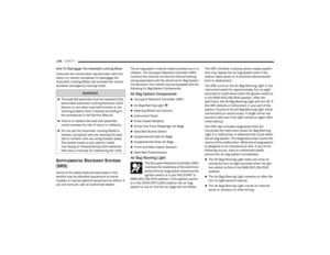 146
146 147
147 148
148 149
149 150
150 151
151 152
152 153
153 154
154 155
155 156
156 157
157 158
158 159
159 160
160 161
161 162
162 163
163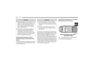 164
164 165
165 166
166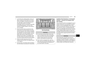 167
167 168
168 169
169 170
170 171
171 172
172 173
173 174
174 175
175 176
176 177
177 178
178 179
179 180
180 181
181 182
182 183
183 184
184 185
185 186
186 187
187 188
188 189
189 190
190 191
191 192
192 193
193 194
194 195
195 196
196 197
197 198
198 199
199 200
200 201
201 202
202 203
203 204
204 205
205 206
206 207
207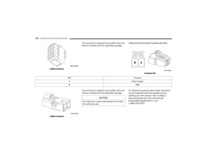 208
208 209
209 210
210 211
211 212
212 213
213 214
214 215
215 216
216 217
217 218
218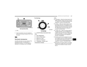 219
219 220
220 221
221 222
222 223
223 224
224 225
225 226
226 227
227 228
228 229
229 230
230 231
231 232
232 233
233 234
234 235
235 236
236 237
237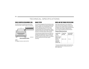 238
238 239
239 240
240 241
241 242
242 243
243 244
244 245
245 246
246 247
247 248
248 249
249 250
250 251
251 252
252 253
253 254
254 255
255 256
256 257
257 258
258 259
259