2022 RAM PROMASTER CITY power steering
[x] Cancel search: power steeringPage 4 of 260
2
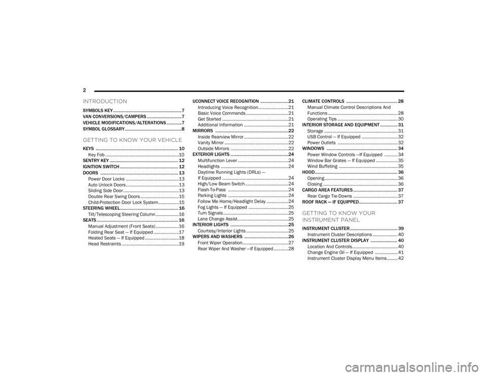
INTRODUCTION
SYMBOLS KEY ...........................................................7
VAN CONVERSIONS/CAMPERS ..............................7
VEHICLE MODIFICATIONS/ALTERATIONS .............7
SYMBOL GLOSSARY.................................................8
GETTING TO KNOW YOUR VEHICLE
KEYS ....................................................................... 10 Key Fob .............................................................10
SENTRY KEY ........................................................... 12
IGNITION SWITCH .................................................. 12
DOORS ................................................................... 13
Power Door Locks ............................................13
Auto Unlock Doors ............................................13
Sliding Side Door ..............................................13
Double Rear Swing Doors ................................15
Child-Protection Door Lock System.................15
STEERING WHEEL.................................................. 16
Tilt/Telescoping Steering Column ...................16
SEATS ...................................................................... 16
Manual Adjustment (Front Seats) ...................16
Folding Rear Seat — If Equipped .....................17
Heated Seats — If Equipped ............................18
Head Restraints ...............................................19 UCONNECT VOICE RECOGNITION ........................21
Introducing Voice Recognition.........................21
Basic Voice Commands ...................................21
Get Started .......................................................21
Additional Information .....................................21
MIRRORS ...............................................................22
Inside Rearview Mirror .....................................22
Vanity Mirror .....................................................22
Outside Mirrors ................................................22
EXTERIOR LIGHTS ..................................................24
Multifunction Lever ..........................................24
Headlights ........................................................24
Daytime Running Lights (DRLs) —
If Equipped .......................................................24
High/Low Beam Switch....................................24
Flash-To-Pass ..................................................24
Parking Lights ..................................................24
Follow Me Home/Headlight Delay ..................24
Fog Lights — If Equipped .................................25
Turn Signals ......................................................25
Lane Change Assist..........................................25
INTERIOR LIGHTS ..................................................25
Courtesy/Interior Lights ...................................25
WIPERS AND WASHERS ......................................26
Front Wiper Operation......................................27
Rear Wiper And Washer —If Equipped ............28 CLIMATE CONTROLS ............................................ 28
Manual Climate Control Descriptions And
Functions .......................................................... 28
Operating Tips .................................................. 30
INTERIOR STORAGE AND EQUIPMENT ............... 31
Storage ............................................................. 31
USB Control — If Equipped .............................. 32
Power Outlets .................................................. 32
WINDOWS ............................................................. 34
Power Window Controls —If Equipped ........... 34
Window Bar Grates — If Equipped .................. 35
Wind Buffeting .................................................35
HOOD....................................................................... 36
Opening............................................................. 36
Closing ..............................................................36
CARGO AREA FEATURES ...................................... 37
Rear Cargo Tie-Downs ..................................... 37
ROOF RACK — IF EQUIPPED................................. 37
GETTING TO KNOW YOUR
INSTRUMENT PANEL
INSTRUMENT CLUSTER......................................... 39
Instrument Cluster Descriptions ..................... 40
INSTRUMENT CLUSTER DISPLAY ....................... 40
Location And Controls...................................... 40
Change Engine Oil — If Equipped ................... 41
Instrument Cluster Display Menu Items ......... 42
22_VM_OM_EN_USC_t.book Page 2
Page 5 of 260

3
TRIP COMPUTER .................................................... 43 Trip Button ........................................................43
Trip Functions ..................................................43
Values Displayed ..............................................44
WARNING LIGHTS AND MESSAGES ................... 44
Red Warning Lights ..........................................44
Yellow Warning Lights ......................................47
Green Indicator Lights......................................49
Blue Indicator Lights ........................................50
White Indicator Lights ......................................50
ONBOARD DIAGNOSTIC SYSTEM — OBD II ....... 50
Onboard Diagnostic System
(OBD II) Cybersecurity ......................................51
EMISSIONS INSPECTION AND MAINTENANCE
PROGRAMS ............................................................ 51
STARTING AND OPERATING
STARTING THE ENGINE ........................................ 52
Automatic Transmission ..................................52
Normal Starting ................................................52
Cold Weather Operation .................................52
Extended Park Starting ....................................52
If Engine Fails To Start .....................................53
After Starting.....................................................53
ENGINE BLOCK HEATER — IF EQUIPPED ............ 53
ENGINE BREAK-IN RECOMMENDATIONS .......... 54
PARKING BRAKE .................................................. 54 AUTOMATIC TRANSMISSION ...............................55
Key Ignition Park Interlock...............................56
Brake/Transmission Shift Interlock (BTSI)
System .............................................................56
9-Speed Automatic Transmission ..................56
POWER STEERING ................................................60
Power Steering Fluid Check ............................60
CRUISE CONTROL — IF EQUIPPED .......................60
To Activate ........................................................61
To Set A Desired Speed ...................................61
To Vary The Speed Setting...............................61
To Accelerate For Passing ...............................61
To Resume Speed ............................................62
To Deactivate ...................................................62
PARKSENSE REAR PARK ASSIST —
IF EQUIPPED ...........................................................62
ParkSense Rear Park Assist Sensors .............62
ParkSense Rear Park Assist Alerts .................63
ParkSense Rear Park Assist Failure
Indications ........................................................64
Cleaning The ParkSense Rear Park Assist
System ..............................................................64
ParkSense Rear Park Assist System Usage
Precautions.......................................................64
PARKVIEW REAR BACK UP CAMERA .................65
REFUELING THE VEHICLE .....................................66 VEHICLE LOADING ................................................. 67
Vehicle Certification Label............................... 67
Gross Vehicle Weight Rating (GVWR) ............. 67
Gross Axle Weight Rating (GAWR) .................. 67
Tire Size ............................................................ 67
Rim Size ............................................................ 67
Inflation Pressure ............................................. 67
Curb Weight ...................................................... 67
Overloading ...................................................... 68
Loading ............................................................ 68
TRAILER TOWING .................................................. 68
Common Towing Definitions............................ 68
Trailer Hitch Classification............................... 70
Trailer Towing Weights (Maximum Trailer
Weight Ratings) ............................................... 71
Trailer And Tongue Weight .............................71
Towing Requirements ..................................... 71
Towing Tips ...................................................... 74
RECREATIONAL TOWING
(BEHIND MOTORHOME) ....................................... 75
Towing This Vehicle Behind Another Vehicle .... 75
Recreational Towing — Automatic Transmission .. 76
DRIVING TIPS ......................................................... 76
Driving On Slippery Surfaces .......................... 76
Driving Through Water ....................................76
22_VM_OM_EN_USC_t.book Page 3
Page 62 of 260
60STARTING AND OPERATING
NOTE:To select the proper gear position for maximum
deceleration (engine braking), move the gear
selector into the ERS position, then simply press
and hold it forward “-”. The transmission will shift
to the range from which the vehicle can best be
slowed down.
POWER STEERING
The standard power steering system provides
increased vehicle response and ease of
maneuverability. The system will provide
mechanical steering capability if power assist is
lost.
If for some reason the power assist is interrupted,
it will still be possible to steer your vehicle. Under
these conditions, you will observe a substantial
increase in steering effort, especially at very low
vehicle speeds and during parking maneuvers.
NOTE:
Increased noise levels at the end of the steering
wheel travel are considered normal and do not
indicate that there is a problem with the power
steering system.
Upon initial start-up in cold weather, the power
steering pump may make noise for a short
amount of time. This is due to the cold, thick
fluid in the steering system. This noise should
be considered normal, and it does not in any
way damage the steering system.
POWER STEERING FLUID CHECK
Checking the power steering fluid level at a defined
service interval is not required. The fluid should
only be checked if a leak is suspected, abnormal
noises are apparent, and/or the system is not
functioning as anticipated. Coordinate inspection
efforts through an authorized dealer. If necessary, add fluid to restore to the proper
indicated level. With a clean cloth, wipe any spilled
fluid from all surfaces Ú
page 241.CRUISE CONTROL — IF EQUIPPED
When engaged, the Cruise Control takes over
accelerator operations at speeds greater than
25 mph (40 km/h).
The Cruise Control buttons are located on the right
side of the steering wheel.
WARNING!
Do not downshift for additional engine braking
on a slippery surface. The drive wheels could
lose their grip and the vehicle could skid,
causing a collision or personal injury.
CAUTION!
Prolonged operation of the steering system at
the end of the steering wheel travel will increase
the steering fluid temperature and it should be
avoided when possible. Damage to the power
steering pump may occur.
WARNING!
Fluid level should be checked on a level surface
and with the engine off to prevent injury from
moving parts and to ensure accurate fluid level
reading. Do not overfill. Use only the
manufacturer recommended power steering
fluid.
CAUTION!
Do not use chemical flushes in your power
steering system as the chemicals can damage
your power steering components. Such damage
is not covered by the New Vehicle Limited
Warranty.
22_VM_OM_EN_USC_t.book Page 60
Page 71 of 260
STARTING AND OPERATING69
Tongue Weight (TW)
The TW is the downward force exerted on the hitch
ball by the trailer. You must consider this as part of
the load on your vehicle.
Trailer Frontal Area
The frontal area is the maximum height multiplied
by the maximum width of the front of a trailer.
Trailer Sway Control (TSC)
The TSC can be a mechanical telescoping link that
can be installed between the hitch receiver and the
trailer tongue that typically provides adjustable
friction associated with the telescoping motion to
dampen any unwanted trailer swaying motions
while traveling.
If equipped, the electronic TSC recognizes a
swaying trailer and automatically applies individual
wheel brakes and/or reduces engine power to
attempt to eliminate the trailer sway.
Weight-Carrying Hitch
A weight-carrying hitch supports the trailer tongue
weight, just as if it were luggage located at a hitch
ball or some other connecting point of the vehicle.
These kinds of hitches are commonly used to tow
small and medium sized trailers.
Weight-Distributing Hitch
The weight-distributing hitch works by applying
leverage through spring (load) bars. They are
typically used for heavier loads to distribute trailer
tongue weight to the tow vehicle's front axle and
the trailer axle(s). When used in accordance with
the manufacturer's directions, it provides for a
more level ride, offering more consistent steering
and brake control thereby enhancing towing
safety. The addition of a friction/hydraulic sway
control also dampens sway caused by traffic and
crosswinds and contributes positively to tow vehicle and trailer stability. Trailer Sway Control
(TSC) and a weight distributing (load equalizing)
hitch are recommended for heavier Tongue
Weights (TW) and may be required depending on
vehicle and trailer configuration/loading to comply
with Gross Axle Weight Rating (GAWR)
requirements.WARNING!
An improperly adjusted Weight Distributing
Hitch system may reduce handling, stability,
braking performance, and could result in a
collision.
Weight Distributing Systems may not be
compatible with Surge Brake Couplers.
Consult with your hitch and trailer manufac-
turer or a reputable Recreational Vehicle
dealer for additional information.
4
22_VM_OM_EN_USC_t.book Page 69
Page 111 of 260
MULTIMEDIA109
NOTE:Only use the numbering listed in the provided
table. Otherwise, the system will not transpose the
message. Did You Know:
Your mobile phone must have the
full implementation of the Message Access Profile
(MAP) to take advantage of this feature. For details
about MAP, visit
UconnectPhone.com.
Apple® iPhone® iOS 5 or later supports reading
incoming text messages only. For further
information on how to enable this feature on your
Apple® iPhone®, refer to your iPhone® “User
Manual”.
Did You Know: Voice Text Reply is not compatible
with iPhone®, but if your vehicle is equipped with
Siri® Eyes Free, you can use your voice to send a
text message.
Siri® Eyes Free — If Equipped
When used with your Apple® iPhone® connected
to your vehicle, Siri lets you use your voice to send
text messages, select media, place phone calls
and much more. Siri uses your natural language to
understand what you mean and responds back to
confirm your requests. The system is designed to
keep your eyes on the road and your hands on the
wheel by letting Siri help you perform useful tasks. To enable Siri, push and hold, then release the
Uconnect Voice Recognition (VR) button on the
steering wheel. After you hear a double beep, you
can ask Siri to play podcasts and music, get
directions, read text messages, and many other
useful requests.
BLUETOOTH® COMMUNICATION LINK
Mobile phones may lose connection to the
Uconnect Phone. When this happens, the
connection can generally be re-established by
restarting the mobile phone. Your mobile phone is
recommended to remain in Bluetooth® ON mode.
POWER-UP
After switching the ignition key from OFF to either
the ON/RUN or ACC position, or after a language
change, you must wait at least 15 seconds prior to
using the system Ú
page 245.
PRE-DEFINED VOICE TEXT REPLY
RESPONSES
Yes. Stuck in
traffic. See you later.
No. Start without
me. I’ll be late.
Okay. Where are
you? I will be 5
25, 30, 45,
60> minutes late.
Call me.
Are you there
yet?
I’ll call you later. I need
directions. See you in 5
minutes.
I’m on my way.
Can’t talk right
now.
I’m lost. Thanks.
5
22_VM_OM_EN_USC_t.book Page 109
Page 134 of 260

132SAFETY
(Continued)
ELECTRONIC BRAKE CONTROL (EBC)
S
YSTEM
Your vehicle is equipped with an advanced
Electronic Brake Control (EBC) system that
includes the Brake Assist System (BAS), Traction
Control System (TCS), Hill Start Assist (HSA),
Electronic Stability Control (ESC), Electronic Roll
Mitigation (ERM) and Trailer Sway Control (TSC). All
systems work together to enhance vehicle stability
and control in various driving conditions and are
commonly referred to as ESC.
Brake Assist System (BAS)
BAS is designed to optimize the vehicle’s braking
capability during emergency braking maneuvers.
The system detects an emergency braking
situation by sensing the rate and amount of brake
application and then applies optimum pressure to
the brakes. This can help reduce braking
distances. The BAS complements the Anti-Lock
Brake System (ABS). Applying the brakes very
quickly results in the best BAS assistance. To
receive the benefit of the system, you must apply
continuous braking pressure during the stopping
sequence (do not “pump” the brakes). Do not
reduce brake pedal pressure unless braking is no
longer desired. Once the brake pedal is released,
the BAS is deactivated.Electronic Stability Control (ESC)
ESC enhances directional control and stability of
the vehicle under various driving conditions. ESC
corrects for over/under steering of the vehicle by
applying the brake of the appropriate wheel to
counteract the above conditions. Engine power
may also be reduced to help the vehicle maintain
the desired path.
Oversteer — when the vehicle is turning more
than appropriate for the steering wheel position.
Understeer — when the vehicle is turning less
than appropriate for the steering wheel position. ESC uses sensors in the vehicle to determine the
vehicle path intended by the driver and compares
it to the actual path of the vehicle. When the actual
path does not match the intended path, ESC
applies the brake of the appropriate wheel to
assist in counteracting the oversteer or understeer
condition.
WARNING!
The Brake Assist System (BAS) cannot prevent
the natural laws of physics from acting on the
vehicle, nor can it increase the traction afforded
by prevailing road conditions. BAS cannot
prevent collisions, including those resulting from
excessive speed in turns, driving on very slippery
surfaces, or hydroplaning. The capabilities of a
BAS-equipped vehicle must never be exploited in
a reckless or dangerous manner, which could
jeopardize the user's safety or the safety of
others.
WARNING!
Electronic Stability Control (ESC) cannot
prevent the natural laws of physics from
acting on the vehicle, nor can it increase the
traction afforded by prevailing road condi
-
tions. ESC cannot prevent accidents, including
those resulting from excessive speed in turns,
driving on very slippery surfaces, or hydro -
planing. ESC also cannot prevent accidents
resulting from loss of vehicle control due to
inappropriate driver input for the conditions.
Only a safe, attentive, and skillful driver can
prevent accidents. The capabilities of an ESC
equipped vehicle must never be exploited in a
reckless or dangerous manner which could
jeopardize the user’s safety or the safety of
others.
22_VM_OM_EN_USC_t.book Page 132
Page 135 of 260
SAFETY133
ESC Activation/Malfunction Indicator Light
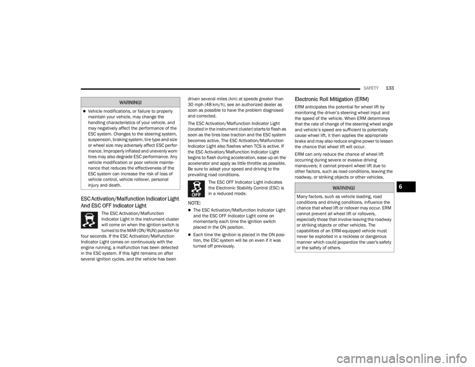
And ESC OFF Indicator Light
The ESC Activation/Malfunction
Indicator Light in the instrument cluster
will come on when the ignition switch is
turned to the MAR (ON/RUN) position for
four seconds. If the ESC Activation/Malfunction
Indicator Light comes on continuously with the
engine running, a malfunction has been detected
in the ESC system. If this light remains on after
several ignition cycles, and the vehicle has been driven several miles (km) at speeds greater than
30 mph (48 km/h), see an authorized dealer as
soon as possible to have the problem diagnosed
and corrected.
The ESC Activation/Malfunction Indicator Light
(located in the instrument cluster) starts to flash as
soon as the tires lose traction and the ESC system
becomes active. The ESC Activation/Malfunction
Indicator Light also flashes when TCS is active. If
the ESC Activation/Malfunction Indicator Light
begins to flash during acceleration, ease up on the
accelerator and apply as little throttle as possible.
Be sure to adapt your speed and driving to the
prevailing road conditions.
The ESC OFF Indicator Light indicates
the Electronic Stability Control (ESC) is
in a reduced mode.
NOTE:
The ESC Activation/Malfunction Indicator Light
and the ESC OFF Indicator Light come on
momentarily each time the ignition switch
placed in the ON position.
Each time the ignition is placed in the ON posi -
tion, the ESC system will be on even if it was
turned off previously.
Electronic Roll Mitigation (ERM)
ERM anticipates the potential for wheel lift by
monitoring the driver’s steering wheel input and
the speed of the vehicle. When ERM determines
that the rate of change of the steering wheel angle
and vehicle’s speed are sufficient to potentially
cause wheel lift, it then applies the appropriate
brake and may also reduce engine power to lessen
the chance that wheel lift will occur.
ERM can only reduce the chance of wheel lift
occurring during severe or evasive driving
maneuvers; it cannot prevent wheel lift due to
other factors, such as road conditions, leaving the
roadway, or striking objects or other vehicles.Vehicle modifications, or failure to properly
maintain your vehicle, may change the
handling characteristics of your vehicle, and
may negatively affect the performance of the
ESC system. Changes to the steering system,
suspension, braking system, tire type and size
or wheel size may adversely affect ESC perfor -
mance. Improperly inflated and unevenly worn
tires may also degrade ESC performance. Any
vehicle modification or poor vehicle mainte -
nance that reduces the effectiveness of the
ESC system can increase the risk of loss of
vehicle control, vehicle rollover, personal
injury and death.
WARNING!
WARNING!
Many factors, such as vehicle loading, road
conditions and driving conditions, influence the
chance that wheel lift or rollover may occur. ERM
cannot prevent all wheel lift or rollovers,
especially those that involve leaving the roadway
or striking objects or other vehicles. The
capabilities of an ERM-equipped vehicle must
never be exploited in a reckless or dangerous
manner which could jeopardize the user's safety
or the safety of others.
6
22_VM_OM_EN_USC_t.book Page 133
Page 146 of 260

144SAFETY
How To Disengage The Automatic Locking Mode
Unbuckle the combination lap/shoulder belt and
allow it to retract completely to disengage the
Automatic Locking Mode and activate the vehicle
sensitive (emergency) locking mode.
SUPPLEMENTAL RESTRAINT SYSTEMS
(SRS)
Some of the safety features described in this
section may be standard equipment on some
models, or may be optional equipment on others. If
you are not sure, ask an authorized dealer.
The air bag system must be ready to protect you in a
collision. The Occupant Restraint Controller (ORC)
monitors the internal circuits and interconnecting
wiring associated with the electrical Air Bag System
Components. Your vehicle may be equipped with the
following Air Bag System Components:
Air Bag System Components
Occupant Restraint Controller (ORC)
Air Bag Warning Light
Steering Wheel and Column
Instrument Panel
Knee Impact Bolsters
Driver and Front Passenger Air Bags
Seat Belt Buckle Switch
Supplemental Side Air Bags
Supplemental Knee Air Bags
Front and Side Impact Sensors
Seat Belt Pretensioners
Air Bag Warning Light
The Occupant Restraint Controller (ORC)
monitors the readiness of the electronic
parts of the air bag system whenever the
ignition switch is in the AVV/START or
MAR/ACC/ON/RUN position. If the ignition switch
is in the STOP/OFF/LOCK position the air bag
system is not on and the air bags will not inflate. The ORC contains a backup power supply system
that may deploy the air bag system even if the
battery loses power or it becomes disconnected
prior to deployment.
The ORC turns on the Air Bag Warning Light in the
instrument panel for approximately four to eight
seconds for a self-check when the ignition switch is
in the MAR/ACC/ON/RUN position. After the
self-check, the Air Bag Warning Light will turn off. If
the ORC detects a malfunction in any part of the
system, it turns on the Air Bag Warning Light, either
momentarily or continuously. A single chime will
sound to alert you if the light comes on again after
initial startup.
The ORC also includes diagnostics that will
illuminate the instrument panel Air Bag Warning
Light if a malfunction is detected that could affect
the air bag system. The diagnostics also record the
nature of the malfunction. While the air bag system
is designed to be maintenance free, if any of the
following occurs, have an authorized dealer
service the air bag system immediately.The Air Bag Warning Light does not come on
during the four to eight seconds when the igni
-
tion switch is first in the MAR/ACC/ON/RUN
position.
The Air Bag Warning Light remains on after the
four to eight-second interval.
The Air Bag Warning Light comes on intermit -
tently or remains on while driving.
WARNING!
The seat belt assembly must be replaced if the
switchable Automatic Locking Retractor (ALR)
feature or any other seat belt function is not
working properly when checked according to
the procedures in the Service Manual.
Failure to replace the seat belt assembly
could increase the risk of injury in collisions.
Do not use the Automatic Locking Mode to
restrain occupants who are wearing the seat
belt or children who are using booster seats.
The locked mode is only used to install
rear-facing or forward-facing child restraints
that have a harness for restraining the child.
22_VM_OM_EN_USC_t.book Page 144