2022 RAM PROMASTER CITY headlights
[x] Cancel search: headlightsPage 4 of 260

2
INTRODUCTION
SYMBOLS KEY ...........................................................7
VAN CONVERSIONS/CAMPERS ..............................7
VEHICLE MODIFICATIONS/ALTERATIONS .............7
SYMBOL GLOSSARY.................................................8
GETTING TO KNOW YOUR VEHICLE
KEYS ....................................................................... 10 Key Fob .............................................................10
SENTRY KEY ........................................................... 12
IGNITION SWITCH .................................................. 12
DOORS ................................................................... 13
Power Door Locks ............................................13
Auto Unlock Doors ............................................13
Sliding Side Door ..............................................13
Double Rear Swing Doors ................................15
Child-Protection Door Lock System.................15
STEERING WHEEL.................................................. 16
Tilt/Telescoping Steering Column ...................16
SEATS ...................................................................... 16
Manual Adjustment (Front Seats) ...................16
Folding Rear Seat — If Equipped .....................17
Heated Seats — If Equipped ............................18
Head Restraints ...............................................19 UCONNECT VOICE RECOGNITION ........................21
Introducing Voice Recognition.........................21
Basic Voice Commands ...................................21
Get Started .......................................................21
Additional Information .....................................21
MIRRORS ...............................................................22
Inside Rearview Mirror .....................................22
Vanity Mirror .....................................................22
Outside Mirrors ................................................22
EXTERIOR LIGHTS ..................................................24
Multifunction Lever ..........................................24
Headlights ........................................................24
Daytime Running Lights (DRLs) —
If Equipped .......................................................24
High/Low Beam Switch....................................24
Flash-To-Pass ..................................................24
Parking Lights ..................................................24
Follow Me Home/Headlight Delay ..................24
Fog Lights — If Equipped .................................25
Turn Signals ......................................................25
Lane Change Assist..........................................25
INTERIOR LIGHTS ..................................................25
Courtesy/Interior Lights ...................................25
WIPERS AND WASHERS ......................................26
Front Wiper Operation......................................27
Rear Wiper And Washer —If Equipped ............28 CLIMATE CONTROLS ............................................ 28
Manual Climate Control Descriptions And
Functions .......................................................... 28
Operating Tips .................................................. 30
INTERIOR STORAGE AND EQUIPMENT ............... 31
Storage ............................................................. 31
USB Control — If Equipped .............................. 32
Power Outlets .................................................. 32
WINDOWS ............................................................. 34
Power Window Controls —If Equipped ........... 34
Window Bar Grates — If Equipped .................. 35
Wind Buffeting .................................................35
HOOD....................................................................... 36
Opening............................................................. 36
Closing ..............................................................36
CARGO AREA FEATURES ...................................... 37
Rear Cargo Tie-Downs ..................................... 37
ROOF RACK — IF EQUIPPED................................. 37
GETTING TO KNOW YOUR
INSTRUMENT PANEL
INSTRUMENT CLUSTER......................................... 39
Instrument Cluster Descriptions ..................... 40
INSTRUMENT CLUSTER DISPLAY ....................... 40
Location And Controls...................................... 40
Change Engine Oil — If Equipped ................... 41
Instrument Cluster Display Menu Items ......... 42
22_VM_OM_EN_USC_t.book Page 2
Page 11 of 260

9
Yellow Warning Lights
Anti-Lock Brake System (ABS) Warning Light Úpage 47
Low Fuel Warning Light Úpage 47
Generic Warning Light Úpage 47
Tire Pressure Monitoring System (TPMS) Warning Light Úpage 47
Vehicle Security Warning Light Úpage 48
Engine Check/Malfunction Indicator Warning Light (MIL) Úpage 48
Electronic Stability Control (ESC) Warning Light Úpage 49
Electronic Stability Control (ESC) OFF Warning Light Úpage 49
Green Indicator Lights
Turn Signal Indicator Lights
Úpage 49
Parking/Headlights On Indicator Light Úpage 49
Front Fog Indicator Light Úpage 49
Cruise Control Indicator Light Úpage 50
Blue Indicator Lights
High Beam Indicator Light
Úpage 50
White Indicator Lights
Speed Warning Indicator Light
Úpage 50
1
22_VM_OM_EN_USC_t.book Page 9
Page 26 of 260

24GETTING TO KNOW YOUR VEHICLE
EXTERIOR LIGHTS
MULTIFUNCTION LEVER
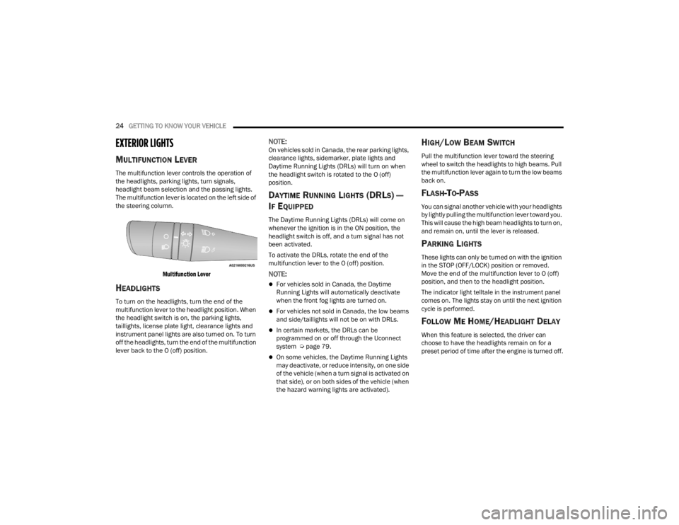
The multifunction lever controls the operation of
the headlights, parking lights, turn signals,
headlight beam selection and the passing lights.
The multifunction lever is located on the left side of
the steering column.
Multifunction Lever
HEADLIGHTS
To turn on the headlights, turn the end of the
multifunction lever to the headlight position. When
the headlight switch is on, the parking lights,
taillights, license plate light, clearance lights and
instrument panel lights are also turned on. To turn
off the headlights, turn the end of the multifunction
lever back to the O (off) position.
NOTE:On vehicles sold in Canada, the rear parking lights,
clearance lights, sidemarker, plate lights and
Daytime Running Lights (DRLs) will turn on when
the headlight switch is rotated to the O (off)
position.
DAYTIME RUNNING LIGHTS (DRLS) —
I
F EQUIPPED
The Daytime Running Lights (DRLs) will come on
whenever the ignition is in the ON position, the
headlight switch is off, and a turn signal has not
been activated.
To activate the DRLs, rotate the end of the
multifunction lever to the O (off) position.
NOTE:
For vehicles sold in Canada, the Daytime
Running Lights will automatically deactivate
when the front fog lights are turned on.
For vehicles not sold in Canada, the low beams
and side/taillights will not be on with DRLs.
In certain markets, the DRLs can be
programmed on or off through the Uconnect
system Ú page 79.
On some vehicles, the Daytime Running Lights
may deactivate, or reduce intensity, on one side
of the vehicle (when a turn signal is activated on
that side), or on both sides of the vehicle (when
the hazard warning lights are activated).
HIGH/LOW BEAM SWITCH
Pull the multifunction lever toward the steering
wheel to switch the headlights to high beams. Pull
the multifunction lever again to turn the low beams
back on.
FLASH-TO-PASS
You can signal another vehicle with your headlights
by lightly pulling the multifunction lever toward you.
This will cause the high beam headlights to turn on,
and remain on, until the lever is released.
PARKING LIGHTS
These lights can only be turned on with the ignition
in the STOP (OFF/LOCK) position or removed.
Move the end of the multifunction lever to O (off)
position, and then to the headlight position.
The indicator light telltale in the instrument panel
comes on. The lights stay on until the next ignition
cycle is performed.
FOLLOW ME HOME/HEADLIGHT DELAY
When this feature is selected, the driver can
choose to have the headlights remain on for a
preset period of time after the engine is turned off.
22_VM_OM_EN_USC_t.book Page 24
Page 43 of 260

GETTING TO KNOW YOUR INSTRUMENT PANEL41
The menu items described below are an example
of what can be found in the vehicle's menu:
Dimmer
Speed Beep
Trip A / B (options are selectable through the
steering wheel stalk)
Buzzer Volume
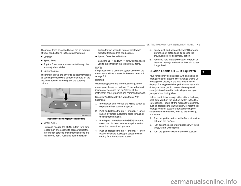
The system allows the driver to select information
by pushing the following buttons mounted on the
instrument panel to the right of the steering
column:
Instrument Cluster Display Control Buttons
MENU Button
Push and release the MENU button for a time
longer than one second to access/select the
information screens or submenu screens of a
main menu item. Push and hold the MENU button for two seconds to reset displayed/
selected features that can be reset.
Up And Down Arrow Buttons:
Using the up or down arrow button allows
you to cycle through the Main Menu Items.
NOTE:If equipped with a Uconnect system, some of the
menu items will be present in the radio head unit
Ú page 79.
Dimmer:
With headlights on and without entering in the
menu, push the up or down arrow button to
increase or decrease the brightness of the
instrument panel, graphics and command buttons.
Selecting An Option Of The Main Menu With
Submenu:
1. Briefly push and release the
MENU
button to
display the first submenu option.
2. Push and release the up or down arrow
button (by single pushes) to scroll through all
the submenu options.
3. Briefly push and release the MENU button to
select the displayed submenu option and to
open the relevant setup menu.
4. Push and release the up or down arrow
button (by single pushes) to select the new
setting for this submenu option. 5. Briefly push and release the MENU
button to
store the new setting and go back to the
previously selected submenu option.
6. Push and hold the MENU button to return to
the main menu (short hold) or the main screen
(longer hold).CHANGE ENGINE OIL — IF EQUIPPED
Your vehicle may be equipped with an engine oil
change indicator system. The “Change Engine Oil”
message will display in the instrument cluster
display. The engine oil change indicator system is
duty cycle based, which means the engine oil
change interval may fluctuate, dependent upon
your personal driving style.
Unless reset, this message will continue to display
each time you turn the ignition switch to the ON/
RUN position. To turn off the message temporarily,
push and release the MENU button. To reset the oil
change indicator system (after performing the
scheduled maintenance), refer to the following
procedure.
1. Turn the ignition switch to the ON position (do not start the engine).
2. Fully push the accelerator pedal slowly, three times, within 10 seconds.
3. Turn the ignition switch to the OFF position.
3
22_VM_OM_EN_USC_t.book Page 41
Page 51 of 260

GETTING TO KNOW YOUR INSTRUMENT PANEL49
Electronic Stability Control (ESC) Warning
Light — If Equipped
The ESC Indicator Light in the
instrument cluster will come on when
the ignition is placed in the ON/RUN or
MAR/ON/RUN position, and when ESC
is activated. It should go out with the engine
running. If the ESC Indicator Light comes on continuously with the engine running, a
malfunction has been detected in the ESC system.
If this light remains on after several ignition cycles,
and the vehicle has been driven several miles
(kilometers) at speeds greater than 30 mph
(48 km/h), see an authorized dealer as soon as
possible to have the problem diagnosed and
corrected.
The ESC OFF Indicator Light and the ESC Indi
-
cator Light come on momentarily each time the
ignition is placed in the ON/RUN or MAR/ON/
RUN position.
Each time the ignition is turned to ON/RUN or
MAR/ON/RUN, the ESC system will be on, even
if it was turned off previously.
The ESC system will make buzzing or clicking
sounds when it is active. This is normal; the
sounds will stop when ESC becomes inactive.
This light will come on when the vehicle is in an
ESC event.
Electronic Stability Control (ESC) OFF
Warning Light — If Equipped
This warning light indicates the ESC is off.
Each time the ignition is turned to
ON/RUN or ACC/ON/RUN, the ESC
system will be on, even if it was turned
off previously.
GREEN INDICATOR LIGHTS
Turn Signal Indicator Lights
When the left or right turn signal is
activated, the turn signal indicator will
flash independently and the
corresponding exterior turn signal lamps
will flash. Turn signals can be activated when the
multifunction lever is moved down (left) or up
(right).
NOTE:
A continuous chime will sound if the vehicle is
driven more than 1 mile (1.6 km) with either
turn signal on.
Check for an inoperative outside light bulb if
either indicator flashes at a rapid rate.
Parking/Headlights On Indicator Light
This indicator light will illuminate when
the parking lights or headlights are
turned on Ú page 24.
Front Fog Indicator Light — If Equipped
This indicator light will illuminate when
the front fog lights are on Ú page 24.
WARNING!
A malfunctioning catalytic converter, as
referenced above, can reach higher
temperatures than in normal operating
conditions. This can cause a fire if you drive
slowly or park over flammable substances such
as dry plants, wood, cardboard, etc. This could
result in death or serious injury to the driver,
occupants or others.
CAUTION!
Prolonged driving with the Malfunction Indicator
Light (MIL) on could cause damage to the
vehicle control system. It also could affect fuel
economy and driveability. If the MIL is flashing,
severe catalytic converter damage and power
loss will soon occur. Immediate service is
required.
3
22_VM_OM_EN_USC_t.book Page 49
Page 52 of 260

50GETTING TO KNOW YOUR INSTRUMENT PANEL
Cruise Control Indicator Light —
If Equipped
This indicator light will illuminate when
the cruise control is activated
Úpage 60.
NOTE:There will be no change in the indicator light when
the desired speed is set.
BLUE INDICATOR LIGHTS
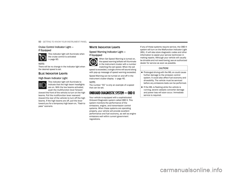
High Beam Indicator Light
This indicator light will illuminate to
indicate that the high beam headlights
are on. With the low beams activated,
push the multifunction lever forward
(toward the front of the vehicle) to turn on the high
beams. Pull the multifunction lever rearward
(toward the rear of the vehicle) to turn off the high
beams. If the high beams are off, pull the lever
toward you for a temporary high beam on, “flash to
pass” scenario.
WHITE INDICATOR LIGHTS
Speed Warning Indicator Light —
If Equipped
When Set Speed Warning is turned on,
the speed warning telltale will illuminate
in the instrument cluster with a number
matching the set speed. When the set
speed is exceeded, a single chime will sound along
with pop-up message of speed warning exceeded.
Speed Warning can be turned on and off in the
instrument cluster display Ú page 40.
NOTE:The number “55” is only an example of a speed
that can be set.
ONBOARD DIAGNOSTIC SYSTEM — OBD II
Your vehicle is equipped with a sophisticated
Onboard Diagnostic system called OBD II. This
system monitors the performance of the
emissions, engine, and transmission control
systems. When these systems are operating
properly, your vehicle will provide excellent
performance and fuel economy, as well as engine
emissions well within current government
regulations. If any of these systems require service, the OBD II
system will turn on the Malfunction Indicator Light
(MIL). It will also store diagnostic codes and other
information to assist your service technician in
making repairs. Although your vehicle will usually
be drivable and not need towing, see an authorized
dealer for service as soon as possible.
CAUTION!
Prolonged driving with the MIL on could cause
further damage to the emission control
system. It could also affect fuel economy and
driveability. The vehicle must be serviced
before any emissions tests can be performed.
If the MIL is flashing while the vehicle is
running, severe catalytic converter damage
and power loss will soon occur. Immediate
service is required.
22_VM_OM_EN_USC_t.book Page 50
Page 82 of 260

80MULTIMEDIA
Language
Display
When the Language button is pressed on the touchscreen, the system displays the different language options. Once an option is selected, the system will
display in the chosen language. The available setting is:
NOTE:Depending on the vehicle’s options, feature settings may vary.
Setting Name Description
Language This setting will change the language of the Uconnect system. The available
languages are English, Français, and Español.
When the Display button is pressed on the touchscreen, the system will display the options related to the theme (if equipped), brightness, and color of the
touchscreen. The available settings are:
NOTE:Depending on the vehicle’s options, feature settings may vary.
Setting Name
Description
Display Mode This setting will allow you to set the brightness manually or have the system
set it automatically. The “Auto” setting has the system automatically adjust
the display brightness. The “Manual” setting will allow the user to adjust the
brightness of the display.
Brightness This setting will allow you to set the brightness when the headlights are on. To
access this setting, Display Mode must be set to Manual. The “With
Headlights On” setting will increase or decrease the brightness with the
headlight on; the “With Headlights Off” will increase or decrease the
brightness with the headlights off.
22_VM_OM_EN_USC_t.book Page 80
Page 152 of 260

150SAFETY
NOTE:
Air bag covers may not be obvious in the interior
trim, but they will open during air bag deploy -
ment.
After any collision, the vehicle should be taken
to an authorized dealer immediately.
Enhanced Accident Response System
In the event of an impact, if the communication
network remains intact, and the power remains
intact, depending on the nature of the event, the
Occupant Restraint Controller (ORC) will determine
whether to have the Enhanced Accident Response
System perform the following functions:
Cut off fuel to the engine (if equipped)
Cut off battery power to the electric motor
(if equipped)
Flash hazard lights as long as the battery has
power
Turn on the interior lights, which remain on as
long as the battery has power or for 15 minutes
from the intervention of the Enhanced Accident
Response System
Unlock the power door locks
Your vehicle may also be designed to perform any
of these other functions in response to the
Enhanced Accident Response System:
Turn off the Fuel Filter Heater, Turn off the HVAC
Blower Motor, Close the HVAC Circulation Door
Cut off battery power to the:
Engine
Electric Motor (if equipped)
Electric Power Steering
Brake booster
Electric park brake
Automatic transmission gear selector
Horn
Front wiper
Headlamp washer pump (if equipped)
NOTE:After an accident, remember to cycle the ignition to
the STOP/OFF position and remove the key from
the ignition switch to avoid draining the battery.
Carefully check the vehicle for fuel leaks in the
engine compartment and on the ground near the
engine compartment and fuel tank before
resetting the system and starting the engine. If
there are no fuel leaks or damage to the vehicle
electrical devices (e.g. headlights) after an
accident, reset the system by following the
procedure described below. If you have any doubt,
contact an authorized dealer.
Enhanced Accident Response System
Reset Procedure
In order to reset the Enhanced Accident Response
System functions after an event, the ignition switch
must be changed from ignition AVV/START or
MAR/RUN to ignition STOP/OFF. Carefully check
the vehicle for fuel leaks in the engine
compartment and on the ground near the engine
compartment and fuel tank before resetting the
system and starting the engine. After an accident,
if the vehicle will not start after performing the
reset procedure, the vehicle must be towed to an
authorized dealer to be inspected and to have the
Enhanced Accident Response System reset.
WARNING!
Deployed air bags and seat belt pretensioners
cannot protect you in another collision. Have the
air bags, seat belt pretensioners, and the seat
belt retractor assemblies replaced by an
authorized dealer immediately. Also, have the
Occupant Restraint Controller System serviced
as well.
22_VM_OM_EN_USC_t.book Page 150