2022 HYUNDAI KONA EV display
[x] Cancel search: displayPage 144 of 548
4
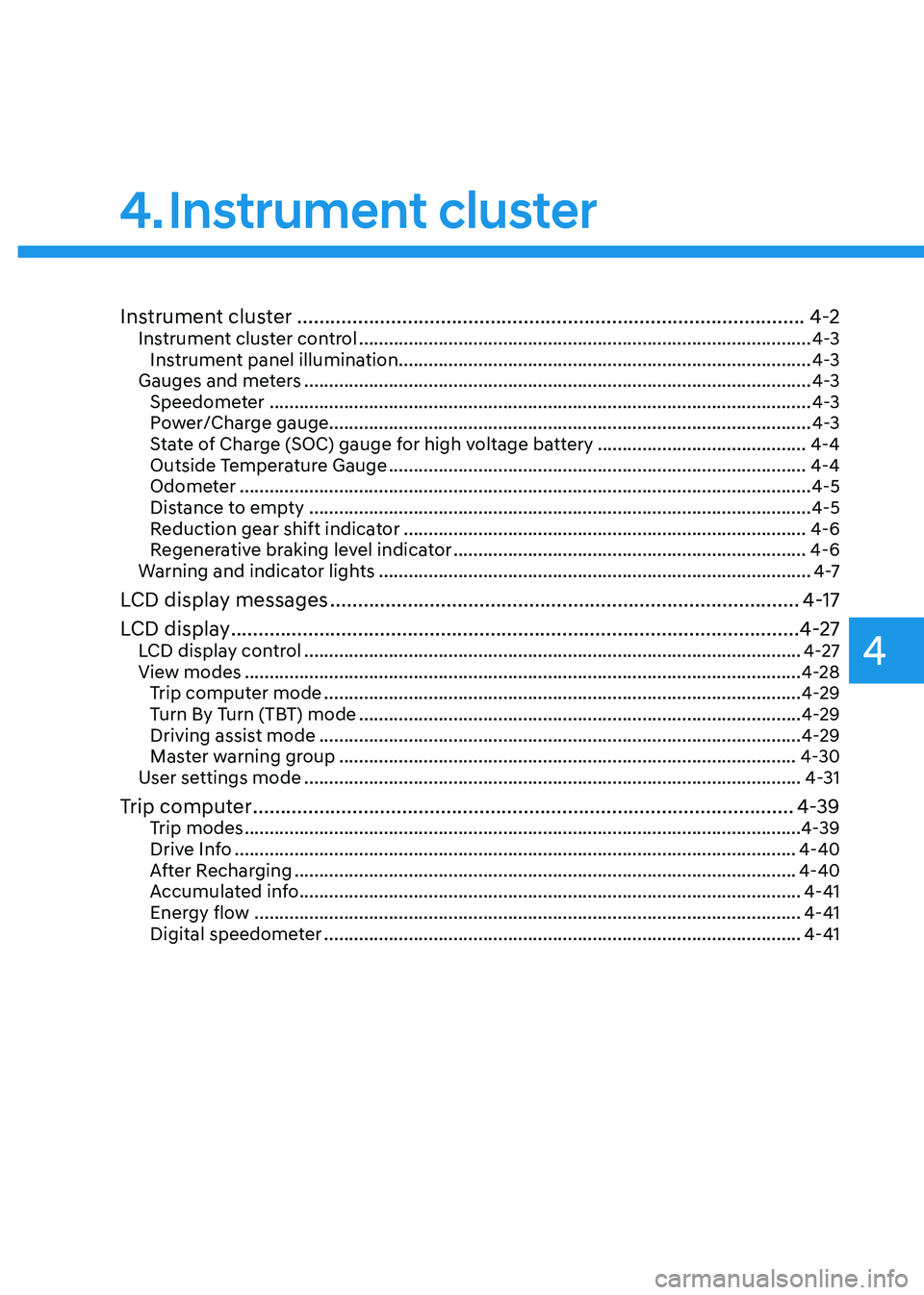
Instrument cluster ............................................................................................ 4-2
Instrument cluster control ........................................................................................... 4-3
Instrument panel illumination ................................................................................... 4-3
Gauges and meters ...................................................................................................... 4-3
Speedometer ............................................................................................................. 4-3
Power/Charge gauge................................................................................................. 4-3
State of Charge (SOC) gauge for high voltage battery ..........................................4-4
Outside Temperature Gauge .................................................................................... 4-4
Odometer ................................................................................................................... 4-5
Distance to empty ..................................................................................................... 4-5
Reduction gear shift indicator ................................................................................. 4-6
Regenerative braking level indicator ....................................................................... 4-6
Warning and indicator lights ....................................................................................... 4 -7
LCD display messages ..................................................................................... 4-17
LCD display ....................................................................................................... 4-27
LCD display control .................................................................................................... 4-27
View modes ................................................................................................................ 4-28
Trip computer mode ................................................................................................ 4-29
Turn By Turn (TBT) mode ......................................................................................... 4-29
Driving assist mode ................................................................................................. 4-29
Master warning group ............................................................................................ 4-30
User settings mode .................................................................................................... 4-31
Trip computer .................................................................................................. 4-39
Trip modes ................................................................................................................ 4-39
Drive Info ................................................................................................................. 4-40
After Recharging ..................................................................................................... 4-40
Accumulated info ..................................................................................................... 4-41
Energy flow .............................................................................................................. 4-41
Digital speedometer ................................................................................................ 4-41
4. Instrument cluster
Page 145 of 548
4-2
Instrument cluster
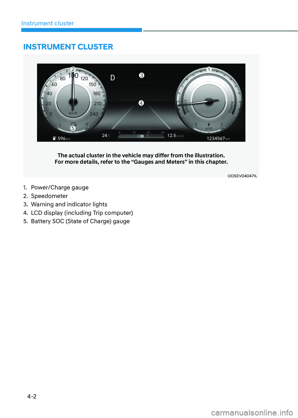
The actual cluster in the vehicle may differ from the illustration.
For more details, refer to the “Gauges and Meters” in this chapter.
OOSEV040471L
Instrument cluster
1. Power/Charge gauge
2. Speedometer
3. Warning and indicator lights
4. LCD display (including Trip computer)
5. Battery SOC (State of Charge) gauge
Page 146 of 548

04
4-3
Instrument cluster control
Instrument panel illumination
OOSEV040056L
When the vehicle’s position lights or
headlamps are on, press the illumination
control button to adjust the brightness of
the instrument panel illumination.
When pressing the illumination control
button, the interior switch illumination
intensity is also adjusted.
WARNING
Never adjust the instrument cluster
while driving. This could result in loss
of control and lead to an accident that
may cause death, serious injury, or
vehicle damage.
OCN7040019L
• The brightness of the instrument
panel illumination is displayed.
• If the brightness reaches the
maximum or minimum level, an alarm will sound.
Gauges and meters
Speedometer
OOSEV040472L
The speedometer indicates the speed of
the vehicle and is calibrated in kilometers
per hour (km/h).
Power/Charge gauge
OOSEV040474L
The Power/Charge gauge shows the
energy consumption rate of the vehicle
and the charge/discharge status of the
regenerative brakes. • POWER :
It shows the energy consumption rate
of the vehicle when driving uphill or
accelerating. The more electric energy is
used, the higher the gauge level. • CHARGE :
It shows the charging status of the
battery when it is being charged by the
regenerative brakes (decelerating or
driving on a downhill road). The more
electric energy is charged, the lower the
gauge level.
Page 147 of 548
Instrument cluster
4-4
State of Charge (SOC) gauge for high
voltage battery
OOSEV040475L
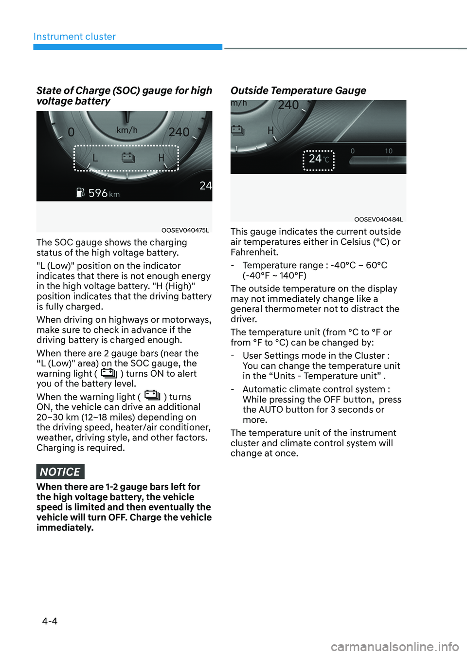
The SOC gauge shows the charging
status of the high voltage battery.
"L (Low)" position on the indicator
indicates that there is not enough energy
in the high voltage battery. "H (High)"
position indicates that the driving battery
is fully charged.
When driving on highways or motorways,
make sure to check in advance if the
driving battery is charged enough.
When there are 2 gauge bars (near the
“L (Low)" area) on the SOC gauge, the
warning light (
) turns ON to alert
you of the battery level.
When the warning light (
) turns
ON, the vehicle can drive an additional
20~30 km (12~18 miles) depending on
the driving speed, heater/air conditioner,
weather, driving style, and other factors.
Charging is required.
NOTICE
When there are 1-2 gauge bars left for
the high voltage battery, the vehicle
speed is limited and then eventually the
vehicle will turn OFF. Charge the vehicle
immediately. Outside Temperature Gauge
OOSEV040484L
This gauge indicates the current outside
air temperatures either in Celsius (°C) or
Fahrenheit.
- Temperature range : -40°C ~ 60°C (-40°F ~ 140°F)
The outside temperature on the display
may not immediately change like a
general thermometer not to distract the
driver.
The temperature unit (from °C to °F or
from °F to °C) can be changed by: - User Settings mode in the Cluster : You can change the temperature unit
in the “Units - Temperature unit” .
- Automatic climate control system : While pressing the OFF button, press
the AUTO button for 3 seconds or
more.
The temperature unit of the instrument
cluster and climate control system will
change at once.
Page 149 of 548
Instrument cluster
4-6
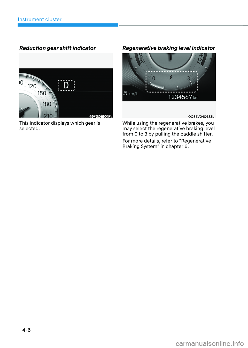
Reduction gear shift indicator
OCN7040013
This indicator displays which gear is
selected. Regenerative braking level indicatorOOSEV040483L
While using the regenerative brakes, you
may select the regenerative braking level
from 0 to 3 by pulling the paddle shifter.
For more details, refer to "Regenerative
Braking System" in chapter 6.
Page 155 of 548

Instrument cluster
4-12
Electric Power Steering (EPS)
Warning Light
This warning light illuminates:
•
When the START/STOP button is in the ON position.
- It illuminates for approximately 3 seconds and then goes off.
• When there is a malfunction with the
Electric Power Steering System.
In this case, we recommend that
you have the vehicle inspected by an
authorized HYUNDAI dealer.
Charging System Warning
Light (for 12-volt battery)
This warning light illuminates:
• When the 12-volt battery level is low
or a failure occurs on the charging
system such as LDC.
• If the warning light turns on while
driving, move the vehicle to a safe
location, turn off and turn on the
vehicle again, and check if the
warning light turns off. If the warning
light remains on, we recommend that
you have the vehicle inspected by an
authorized HYUNDAI dealer.
• Even if the warning light turns off, we
recommend that you have the vehicle
inspected by an authorized HYUNDAI
dealer.
If you drive the vehicle while the
warning light is on, vehicle speed may
be limited and the 12-volt battery may
be discharged.
à LDC : Low voltage DC-DC Converter. Master Warning Light
This indicator light illuminates:
•
When there is a malfunction in the
below systems.
- Forward Collision-Avoidance Assist malfunction (if equipped)
- Forward Collision-Avoidance Assist radar blocked (if equipped)
- Blind-Spot Collision Warning malfunction (if equipped)
- Blind-Spot Collision Warning radar blocked (if equipped)
- LED headlamp malfunction (if equipped)
- High Beam Assist malfunction (if equipped)
- Smart Cruise Control with Stop & Go malfunction (if equipped)
- Smart Cruise Control with Stop & Go radar blocked (if equipped)
- Tire Pressure Monitoring System (TPMS) malfunction
To identify the details of the warning,
look at the LCD display.
Page 156 of 548
04
4-13
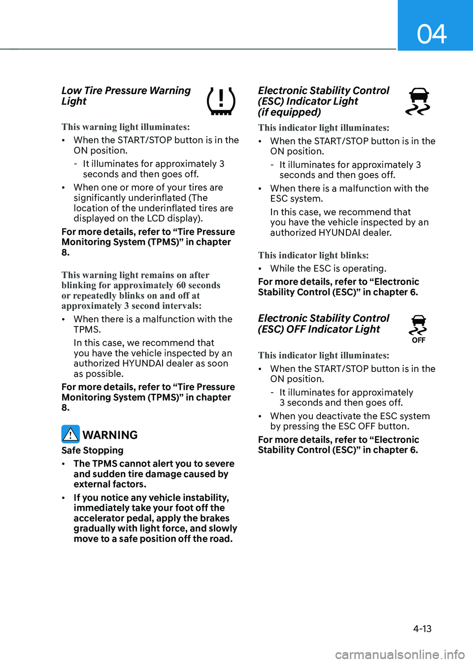
Low Tire Pressure Warning
Light
This warning light illuminates:
•
When the START/STOP button is in the ON position.
- It illuminates for approximately 3 seconds and then goes off.
• When one or more of your tires are
significantly underinflated (The
location of the underinflated tires are
displayed on the LCD display).
For more details, refer to “Tire Pressure
Monitoring System (TPMS)” in chapter 8.
This warning light remains on after
blinking for approximately 60 seconds
or repeatedly blinks on and off at
approximately 3 second intervals:
• When there is a malfunction with the TPMS.
In this case, we recommend that
you have the vehicle inspected by an
authorized HYUNDAI dealer as soon as possible.
For more details, refer to “Tire Pressure
Monitoring System (TPMS)” in chapter 8.
WARNING
Safe Stopping • The TPMS cannot alert you to severe
and sudden tire damage caused by
external factors.
• If you notice any vehicle instability,
immediately take your foot off the
accelerator pedal, apply the brakes
gradually with light force, and slowly
move to a safe position off the road. Electronic Stability Control
(ESC) Indicator Light (if equipped)
This indicator light illuminates:
•
When the START/STOP button is in the ON position.
- It illuminates for approximately 3 seconds and then goes off.
• When there is a malfunction with the
ESC system.
In this case, we recommend that
you have the vehicle inspected by an
authorized HYUNDAI dealer.
This indicator light blinks:
• While the ESC is operating.
For more details, refer to “Electronic
Stability Control (ESC)” in chapter 6.
Electronic Stability Control
(ESC) OFF Indicator Light
This indicator light illuminates:
• When the START/STOP button is in the ON position.
- It illuminates for approximately 3 seconds and then goes off.
• When you deactivate the ESC system
by pressing the ESC OFF button.
For more details, refer to “Electronic
Stability Control (ESC)” in chapter 6.
Page 160 of 548
04
4-17
lcD DIsplay messages
Shift to P
This warning message is displayed if you
try to turn off the vehicle when the gear
is not in the P (Park) position.
At this time, the START/STOP button
changes to the ACC position (If you press
the START/STOP button once more, it will
turn to the ON position).
Low key battery
This warning message is displayed if the
battery of the smart key is discharged
while changing the START/STOP button
to the OFF position.
Press START/STOP button while turning wheel
This warning message is displayed if the
steering wheel does not unlock normally
when the START/STOP button is pressed.
You should press the START/STOP button
while turning the steering wheel right
and left.
Check steering wheel lock system
This warning message is displayed if the
steering wheel does not lock normally
while the START/STOP button changes to the OFF position.
Press brake pedal to start vehicle
This warning message is displayed if the
START/STOP button changes to the ACC
position twice by pressing the button
repeatedly without depressing the brake pedal.
You can start the vehicle by depressing
the brake pedal.Key not in vehicle
This warning message is displayed if the
smart key is not in the vehicle when you
press the START/STOP button.
When attempting to start the vehicle,
always have the smart key with you.
Key not detected
This warning message is displayed if the
smart key is not detected when you press
the START/STOP button.
Press START/STOP button again
This message is displayed if you were
unable to start the vehicle when the
START/STOP button was pressed.
If this occurs, attempt to start the vehicle
by pressing the START/STOP button again.
If the warning message appears each
time you press the START/STOP button,
we recommend you to have your vehicle
inspected by an authorized Hyundai
dealer.
Press START/STOP button with key
This warning message is displayed if you
press the START/STOP button while the
warning message "Key not detected" is
displayed.
At this time, the immobilizer indicator
light blinks.